TMS800E OPERATOR’S MANUAL
OPERATING CONTROLS AND PROCEDURES
impending capacity when the system has been properly preset by the operator. The control panel is mounted in the front console of the operator’s cab. When an overload condition is sensed, the system provides the operator with a visual and audible warning, and locks out the control levers to prevent lowering the boom, extending the boom, or raising the main or auxiliary hoist cables. Three additional features are included within the RCL system: •
Swing Angle Set Limitation
•
Work Area Definition
•
Anti-two Block Device
Control Lever Lockout System The control lever lockout system consists of hydraulic solenoid valves located in the directional control valves. The valves are activated in such a manner as to prevent worsening the condition, i.e. boom down, telescope out, or hoist up. The control lever lockout system is used with the anti-two-block system or the rated capacity limiter (RCL) system. The RCL sends a signal to the canbus system which turns off the solenoids on the directional valves.
Crane Travel Operation Active Restraints
Swing Angle Set Limitation allows left and right swing angle to be preset. When the preset angle is reached, the system will provide an audible warning.
Seat Belts
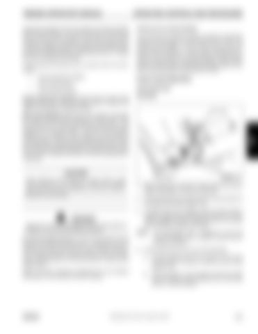
Latch Plate
Work Area Definition allows the crane operator to describe the crane’s working area by setting up “virtual walls”. They are referred to as virtual walls because they exist in the system and are not real walls. The virtual walls represent obstacles (i.e. buildings, towers, poles, etc.) in the crane’s working range. They are set by defining points along the outer limits of the working area with the tip of the boom. Once the working area has been defined, the system will provide a visual and an audible warning if the boom approaches a virtual wall.
3 Buckle
CAUTION When defining virtual walls (s). always allow a safe working distance to any obstacles. Never work outside a safe working area as defined by common practice, standards, and manuals.
Push Button
1.
Before fastening a seat belt, always adjust the driver’s seat to the position in which you will drive.
2.
Pull the belt across your lap and push the latch plate into the buckle until it clicks (Figure 3-9).
3.
To reduce the risk of sliding under the belt during a collision, position the belt across your lap as low on your hips as possible and pull it toward the door to a snug fit so the retractor can take up the slack.
WARNING There are no cut-outs associated with the swing angle set limitation or the work area definition features. An Anti-two Block Device is also incorporated into the system to prevent the hook block or headache ball from coming into contact with the boom nose or boom extension. This condition will also cause a lockout of hoist up, boom down, and telescope out, and also provide a visual and an audible alarm. Refer to the RCL Operator’s Handbook for more detailed information on the function of the RCL system.
GROVE
FIGURE 3-9
NOTE:
4.
The lap/shoulder belt is designed to lock only during a sudden stop or impact. At other times it should move freely.
If the shoulder belt is too snug, do the following: a.
Pull the shoulder belt out (A) at least 130 mm (5 in) so that when it is let go, it returns to your chest (Figure 3-10).
b.
Then pull down on the shoulder belt (B) the least amount needed to ease pressure but no more than 25 mm (1 inch) and let go.
Published 09-14-2012, Control # 132-07
3-31


