TMS800E OPERATOR’S MANUAL
7.
SET-UP AND INSTALLATION
Connect RCL connector (1, Figure 4-35) to RCL connection box. The cable is stowed in the 23 ft (7m) section.
1
6642-28
4. 6642-27
1
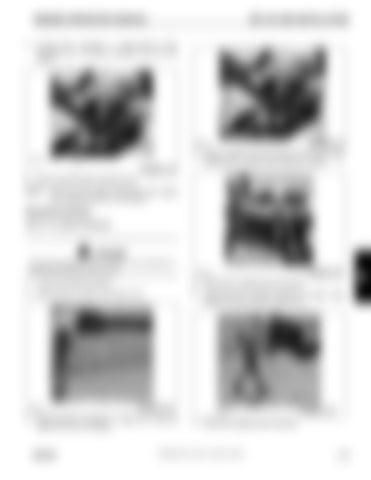
8.
FIGURE 4-37
Remove retainer clip and remove the left side stinger retaining pin (1, Figure 4-38). Place pin in holder.
FIGURE 4-35
Remove tag line before operating crane.
NOTE:
Reeve the hoist cable as described under rigging and unrigging procedure in this section.
Stowing Procedure 56 ft (17.1 m) Boom Extension
1
DANGER To prevent serious injury or death, do not stand on decking until extensions are secure.
FIGURE 4-38
6642-26
1.
Lower boom below horizontal.
5.
Raise boom to slightly above horizontal.
2.
Attach tag line to stinger nose Figure 4-36.
6.
Using tag line to control movement of stinger, swing stinger into stowed position Figure 4-39.
1
6642-23
3.
FIGURE 4-36
Disconnect RCL connection (1, Figure 4-37). Stow the cable in the 23 ft (7 m) section.
GROVE
6642-29
7.
FIGURE 4-39
Raise boom slightly above horizontal.
Published 09-14-2012, Control # 132-07
4-19
4


