CHAPTER 7 ADJUSTMENTS
A CAUTION BEFORE proceeding to perform any adjust ments on the Spreader, exercise the MAN DATORY SAFETY SHUTDOWN PROCEDURE (page 8).
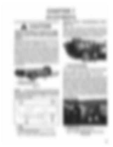
APRON DRIVE TRANSMISSION INPUT (Fig. 7-3) Chain Tension Blocks are provided for the Drive Chains on the Apron Drive Transmission. Chain ten sions should be checked after every 50 hours of opera tion. Chain tension is adjusted by loosening the Bolt and adjusting the Block position on either Chain.
APRON CHAIN TENSION (Fig. 7-1 & 7-2) Apron Chain tension should be checked after every 50 hours of operation. Apron Chain tension is important because too much slack will cause the Chain to ride off the Sprockets and, too much tension will cause prema ture wear and early failure of the Chain and/or Sprock ets. Adjust the Take-up Bolts, on both front comers of the Spreader Box Frame,evenly until the Chain is 1/2" (13 mm) from the Channel Crossmember at the rear of the Spreader.
1 • Chain Tensloner Blocks 2 • Apron Drive Transmission
Fig. 7-3: Apron Drive ChaIn Adjustment Detail
MAIN DRIVE CHAIN (Figs. 7-4 & 7-5)
1 • Frame Crossmember 2 • Right Side Apron Take-up
Fig. 7-1
NOTE:
In freezing temperatures, BE SURE to keep the Box Floor and Apron Chain Slats clean. Operate the machine empty (before loading) to make sure nothing is frozen tight.
The Main Drive Chain, located in the front of the Spreader, is provided with a Chain Tightener Block. To adjust Chain tension, remove the Front Cover and ad just the position of the Block until the proper Chain tension is obtained. Chain tension should be checked after every 50 hours of operation. The Chain is proper ly tensioned when it can be deflected approximately 1/4 to 1/2" (6 to 13 mm), with hand pressure applied at the midpoint of the Chain, between the Drive and Driven Sprockets.
(
1· Rear 2· Front 3 • Frame Crossmember Channel (1/2" Clearance) 4 • Apron Chain Take·up Bolt
Fig. 7-2: Apron Chain Adjustment Detail
1 • Indicator Lever 2 • Main Drive Chain Tightener Block
FIg. 7-4: Main Drive Chain (Front Cover Removed)
23


