13 minute read
SAFETY (Continued) A WARNING


PINCH POINT BETWEEN ENDGATE AND SPREADER BOX. STAY CLEAR OF THIS AREA WHEN ENDGATE IS BEING LOWERED.
FAILURE TO HEED COULD RESULT IN DEATH OR SERIOUS INJURY.
THE OWNER IS RESPONSIBLE FOR MAKING INFORMATION AVAILABLE ON THE SAFE USE AND PROPER MAINTENANCE OF THIS MACHINE. DO NOT START, OPERATE OR WORK ON THIS MACHINE UNTIL YOU HAVE CAREFULLY READ AND UNDERSTAND THE CONTENTS OF THIS MANUAL.
IF YOU HAVE QUESTIONS ON OPERATION, ADJUSTMENT OR MAINTENANCE OF THIS MACHINE OR NEED AN OPERATOR'S MANUAL, CONTACT YOUR GEHL DEALER OR GEHL COMPANY, WEST BEND, WISCONSIN 53095 MODEL AND SERIAL NUMBERS WILL BE REQUIRED.
FAILURE TO HEED COULD RESULT IN DEATH OR SERIOUS INJURY.
093387
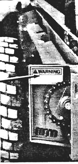
ROTATING COMPONENTS CAN CATCH/CUT/PINCH HAND. KEEP HANDS OUT. CLOSE OR REPLACE GUARD BEFORE OPERATING MACHINE.

FAILURE TO HEED COULD RESULT IN DEATH OR SERIOUS INJURY.
CONTROLS & SAFETY EQUIPMENT
This machine is provided with features for operator GUARDS & SHIELDS (Fig. 5-1) safety and convenience.
Acaution
Become familiar with and know how to use ALL safety devices and controls on this machine BEFORE attempting to operate the unit. Know how to stop machine operation BEFORE starting It.
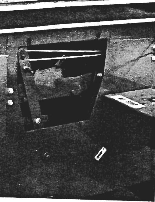
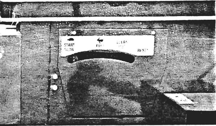
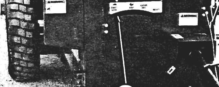
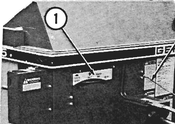
FUNCTION CONTROL (Fig. 5-1)

This GEHL Box Spreader features a Function Control which allows the Conveyor Apron to be operated for unloading and to stop the Beater(s) for Box c1eanout. The Control Mechanism is linked to the tractor by a Control Rope. An Indicator. which protrudes thru a slot in the Front Cover, is provided to show the operation mode, according to a Decal attached above the slot.
NOTE: BEFORE proceeding to load or after unloading and cleaning-out the Spreader Box, reset the Indicator to the "Start/Slow" position.
A Caution
BEFORE proceeding to perform any work on the unit and BEFORE removing or opening any Guards or Covers, BE SURE to exercise the MANDATORY SAFETY SHUTDOWN PRO· CEDURE (page 8). Replace ALL Guards and Covers BEFORE resuming operation.
Whenever possible and without affecting machine operation, Guards, Shields and/or hinged Covers have been used on this equipment to protect potentially hazardous areas. In many places, Decals are also provided to warn of potential dangers as well as to display special operating procedures.
HITCHJACK (Fig. 5-2)

A Hitchjack is furnished with the Spreader to support the machine when the tractor is disconnected as well as to facilitate aligning the Hitch Clevis with the trac· tor draw bar for hookup.


A Hitchjack is furnished with the Spreader to support the machine when the tractor is disconnected as well as to facilitate aligning the Hitch Clevis with the tractor drawbar for hookup.
When the Jack is NOT being used to support the Spreader, it can be pivoted up to the "storage" position. Wrap the Chain around the Jack Handle, before inserting the Locking Pin through the Hub holes to prevent the Handle from dragging on the ground.
Awarning
BE SURE the Locking Pin Is properly seated Into the holes through the Jack Tube and the Hub on the Spreader A-Frame, BEFORE the tractor Is disconnected.
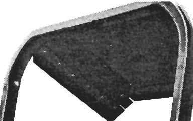
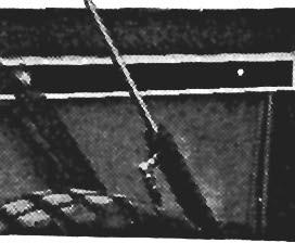
(OPTIONAL) HYDRAULIC ENDGATE (Fig. 5-3)
Awarning
Stay Clear of the "pinch point" area, between the Endgate and Spreader Box, while the Endgate Is being lowered. Failure to heed can result In death or serious Injury.
The Manure Spreader can be equipped with an optional Hydraulic Endgate which uses either one or two tractor-operated Hydraulic Cylinders to raise and lower the Endgate. The Endgate should be ordered and installed on any unit which is frequently used to haul manure over a public highway.
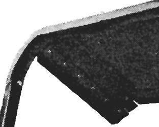
SAFETY CHAIN & AUXILIARY LIGHTING (Fig. 5-4) A CAUTION
ALWAYS follow state and local regulations regarding a safety chain and auxiliary lighting when towing farm equipment on a public highway. BE SURE to check with local law enforcement agencies for your own particular regulations. Unless otherwise prohibited, use a Slow-moving Vehicle Emblem. Only a safety khaln. (NOT an · elastic or nylon/plastic tow strap) should be used to retain connection between the towing and towed machines, In the event of separation of the primary attach· Ing system.
1
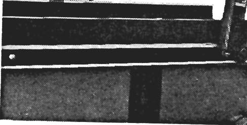
• Optional Endgate
2
• Optional Endgate Control Cylinder
Fig. 5·3: Optional Hydraulic Endgate (Installed)
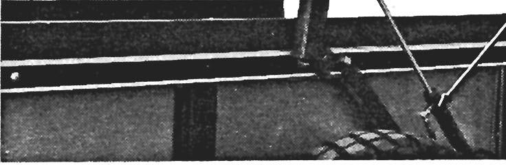
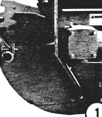
1 • Safety Chain Fastened Around Spreader A·Frame
2 • Locking Hltchpln
3 • Safety Chain & Clevis
Fig. 5-4
As required or when desired, the Spreader should be equipped with a Safety Chain and auxiliary lighting for transporting the unit on·a public highway. The Chain should be routed as shown in the illustration. Refer to the Optional Features & Accessories chapter of this manual for ordering information.
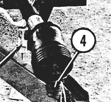
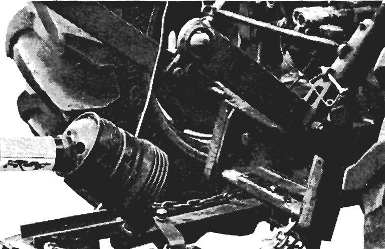
TELESCOPING PTO DRIVE (Fig. 5-5 & see Fig. 5-2)
The Telescoping PTO Drive is designed to rotate freely inside the Drive Shield Tubes.
The Telescoping PTO Drive is provided with a Springloaded Locking Device on each end to positively lock the Drive connection onto the tractor PTO shaft and the Spreader Drive Input Shaft. Depress the Locking Device, against the Spring tension, and slide the Yoke onto its respective Drive Shaft. Release the Locking Device and move the Yoke ahead or back until the Lock engages into the groove of its respective Shaft.
A Warning
BE SURE the Telescoping Drive rotates freely Inside the Drive Shield Tubes at all times. These Metal-shielded Tubes MUST NOT be anchored.
NOTE: AL WA YS orient and attach the PTO Drive with the CV end coupled to the tractor PTO shaft.
A Warning
The Telescoping PTO Drive Is provided with a Spring-loaded Locking Device on each end to positively lock the Drive connection onto the tractor PTO shaft and the Spreader Drive Input Shaft. Depress the Locking Device, against the Spring tension, and slide the Yoke onto Its respective Drive Shaft. Release the Locking Device and move the Yoke ahead or back until the Lock engages Into the groove of Its respective Shaft.
NOTE: For your convenience when the Spreader disconnected from the tractor, the PTO can be placed over the PTO Hanger provided.
Chapter 6 Operation
Awarning
Read and observe ALL safety Decals on the unit BEFORE operating It. Do NOT attempt to operate this equipment until ALL factory-Installed Guards and Shields are properly secured In place. BEFORE starting the tractor engine and running the Spreader, review and comply with ALL applicable recommendations set forth In the SAFETY chapter of this manual.
General Information
This GEHL Box Spreader is designed and constructed to handle semi-solid and solid manures. Its low profile makes it convenient for loading with barn cleaners, skid loaders or front end loaders. It features high strength GEHL-Steel Box Sides, a GEHL-tuffplywood floor, a 90' Beater Drive Transmission, an Apron Drive Transmission and Shear Bolt overload protection on both the Apron Transmission Driven Sprocket and the Main Drive Sprocket.
Nutrient Value for Crop Production
Table 1 shows estimated fertilizer compositions of waste applied to the land (wet basis). Nutrient contents vary widely, so these data are guidelines. For specific situations, have your manure analyzed. Conversion factors:
Multiply PzOs by 0.44 to convert to elemental P.
Multiply KzO by 0.83 to convert to elemental K. 27,150 gal = 1 acre-inch (a-in).
Table 1 of Nutrients In Solid Manure
Table 2: Mineralized Organic Nitrogen
Amount mineralized (released to crops) during first cropping season after application of animal manure.
Application Rate (Fig. 6-1)
Several factors influence the rate of manure being discharged. These factors include: the Apron Drive Transmission speed, the ground speed, the type or consistency of the manure and the PTO RPM. -
NOTE: Under NO circumstances should the rated 540 or (optional) 1000 RPM of your the Spreader be exceeded.
Available N is nitrogen the plant can use. Total N is mostly organic and ammonium nitrogen. Organic N is slow releasing N. Ammonium N is equivalent to commercial fertilizer and, except for that lost to the air, can be used by plants in the application year. Organic nitrogen must be released before plants can use it.
Variable amounts of organic nitrogen are released in a plant-available form during the first cropping year after application. Table 2 summarizes the percentages of organic nitrogen released (mineralized) during the first cropping season. Organic N released during the second, third and fourth cropping years after initial application is usually about 50%, 25%, and 12.5%, respectively, of that mineralized during the first cropping season.
Nearly all of the phosphorus and potassium in animal wastes are available for plant use the year of application. After a few years of regular waste applications, the amounts available are about the same as one year's application.
To coincide with a total "Waste Management System", the application rate for your own particular requirements can be determined through soil testing and the data provided in the two tables, with the assistance of a local University Extension Office. The preceding "Nutrient Value" information is reproduced with the consent of Midwest Plan Service.
1 ·56" (1422 mm)
Assumptions:
(1) - Manure Density = 60 Ib/ft 3
(2) - Box Filled To Struck Capacity
(3) - Rated PTO Speed
The amount of surface spread manure being applied can be measured by constructing an inside-measured, 56" x 56" (1,422 mm x 1,422 mm) Collection Frame out of 2 x 4's and plastic sheeting. The manure collected on the Frame can be removed and weighed to determine how many tons per acre are being applied.
If the weight of the manure caught on the Collection Frame weighed 1-1/2 pounds, the number of tons per acre would be:
= 1 Ton/Acre x 1-1/2
= 1-1/2 Tons/Acre
Emergency Shut-down
In an emergency or in case a foreign object becomes lodged in the Rear Beater area, STOP Spreader operation IMMEDIATELY by disengaging the tractor PTO. BE SURE to exercise the MANDATORY SAFETY SHUTDOWN PROCEDURE (page 8) when leaving the tractor seat to correct the problem.
Tractor Hook-up (Fig. 6-2)
NOTE: By design, this Spreader can only be properly hooked-up to a tractor which has PTO and hitch dimensions conforming to ASAE Standard S203. Horsepower required may vary according to the consistency of manure, ground speed and terrain.
Proper operation requires a tractor with sufficient horsepower to run the PTO and size to counterbalance the weight of a loaded Spreader.
Caution
Use a locking hltchpln (a pin with a positive retaining device) to connect the Spreader to the tractor drawbar.
PTO Connection (Fig. 6-2)
NOTE: GEHL Box Spreaders are deSigned for 540 RPM PTO operation only. To prevent Drive Line damage, avoid operating at higher speeds.
It is very important that a measurement of 14" (355 mm) is established and maintained from the end of the PTO shaft to the drawbar pin hole.
1 - Tractor PTO Shaft·
2·14" (355 mm) for 540 RPM
3 • Sliding Coupler Lock
4·6 to 12" (150 to 300 mm) • 8" (203 mm) Standard·
5 • Locking Hltchpln
6 • Tractor Drawbar
• Tractor MUST comply with ASAE Standard S203
Fig. 6·2
Awarning
BE SURE that the Telescoping PTO Coupler Is properly secured to the tractor PTO shaft. Likewise, BE SURE that the Rotating Shields turn freely BEFORE starting the tractor en· glne.
Telescoping PTO Drive (Fig. 6-3)
NOTE: Do NOT attempt to use a hammer to aid in attaching Drive Connections on either end.
The Spreader is equipped with a Constant Velocity Telescoping PTO Drive Shaft. This constant velocity capability, while cornering, results in a smooth, quiet running Drive Line, without power fluctuation.
Fig.
NOTE: Whether in operation or NOT, the Maximum Joint angle MUST NOT exceed 80'. Any angle, greater than 80', WILL result in damage to the Joint. In addition, for continuous operation, the maximum Joint angle should be limited to 35'. Wide-angle Constant Velocity Joints are NOT designed for use as angledgearboxes. Any continuous operation, at angles greater than 35', will result in shortening Joint life.
Spreader Drive Input Shaft Connection
Clean and lightly grease the splines on the Spreader Drive Input Shaft and Yoke of the Telescoping PTO Drive. Slide the Yoke onto the Input Shaft. Move the Yoke back and forth until the Yoke Lock engages the groove in the Input Shaft.
Tractor Connection
After the correct distance is obtained, slide back the Coupler Lock and attach the PTO Drive to the tractor PTO shaft. Make sure that the Coupler locks onto the PTO shaft; slide it back and forth until it locks.
NOTE: To prevent damage to the Telescoping Drive, NEVER allow the tractor's rear tires to make contact with the Telescoping Drive while making sharp turns. Be especially careful when pulling the Spreader with a tractor equipped with dual rear tires and/or a 3-point hitch.
Hydraulic Connections for Optional Endgate (Figs. 6-4 & 6-5)
Before starting the tractor, connect the hydraulic Hoses, for the Endgate Control Cylinder(s), to an appropriate pair of remote outlets on the tractor. Then, operate the tractor valve to fill the hydraulic lines and operate the Cylinder(s) to raise and lower the Endgate.
A Warning
Stay Clear of the "pinch point" area, between the Endgate and Spreader Box, while the Endgate Is being lowered. Failure to heed can result In death or serious Injury.
Check the tractor hydraulic fluid level after filling the Spreader Cylinder(s). Add fluid to the tractor system, as required.
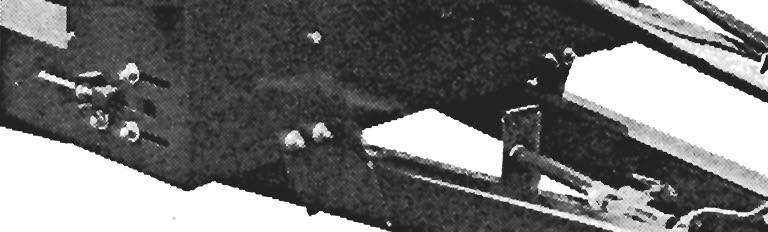
LOADING THE SPREADER (Fig. 6-5)
Although GEHL Box Spreaders are designed and built to handle solid and semi-solid manures, many potential problems can be avoided when manure is spread, if the following guidelines are established and met:
NOTE: To prevent damage to the Drive Line, Conveyor Apron and Beater(s), foreign objects, such as stones, heavy timber or metal, should NEVER be placed into the Spreader.
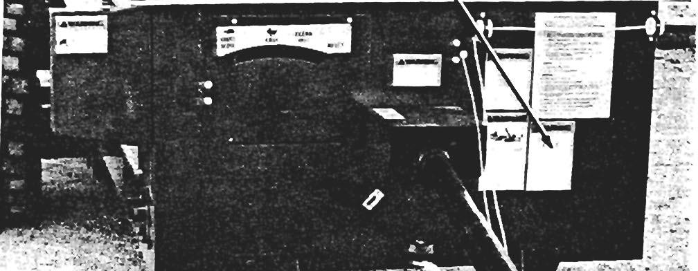
1 - Beater & Apron Conditions Indicator
2 • Beater & Apron Control Rope
3 • Optional Endgate Hydraulic Connections
4 • Telescoping PTO Drive Metal Shields
Fig. 6-5
1. BE . SURE the Control Indicator is in the "Start/Slow" position before starting to load the Spreader.
2. When loading hard-packed manure into the Spreader with a Loader Bucket, try to breakup the large chunks. Always load from the front to the back of the Spreader. Avoid heaping material at the back. Do NOT pack the Beater(s) with manure.
3. In winter or freezing temperatures, make sure the Beater, Apron and Endgate (as applicable) are free (NOT frozen) before loading the Spreader and applying PTO power. Test-run unit before loading it. BE SURE the Endgate (if provided) is closed before loading.
4. Always keep the Conveyor Apron Chain tight. Proper Chain tension can be seen when the Chain is 1/2" (13 mm) from the Channel Crossmember at the rear of the Spreader.
UNLOADING & SPREADING (Fig. 6-5)
GEm... Box Spreaders are furnished with an Apron Speed Change Mechanism to operate the Conveyor Apron at a normal unloading (slower) or faster (cleanout) speed. Operation of the Speed Change Mechanism is controlled by the Function Control Rope from the tractor seat.
NOTE: If the Conveyor is heavily loaded, it will NOT shift until the load is reduced.
To unload and spread manure and prevent unnecessary stress on the drive components, observe the following guidelines:
1. Where provided, raise the Spreader Endgate.
2. With the Control Indicator in the "Start/Slow" position and the tractor at low RPM, engage the tractor PTO and gradually bring the tractor up to speed. When in the "Start" position, the Beater is on and the Apron is running in low. If the Beater starts and stops or does NOT begin to turn, stop the PTO, exercise the MANDATORY SAFETY SHUTDOWN PROCEDURE (page 8) and check if the Main Drive Shear Bolt has failed.
NOTE: The Apron operates whenever the tractor PTO is engaged. When the Apron is on, if the load of manure does NOT move towards the Beater(s), exercise the MANDATORY SAFETY SHUTDOWN PROCEDURE (page 8) and check to see if the Apron Drive Shear Bolt has failed. Correct the causers) of Shear Bo/t(s) failure before proceeding.
3. When Spreader is nearly unloaded, pull the Rope to move the Control Indicator into the "Fast" position. In the "Fast" position, the Beater is on and the Apron is running in high.
4. To completely empty the Spreader Box, pull on the Control Rope to move the Indicator to the "Cleanout" position. In the "Cleanout" position, the Beater is off and the Apron is running in high.
S. After the Spreader is cleaned-out, DISENGAGE the PTO and pull the Control Rope to return the Indicator to the "Start/Slow" position.
Overload Protection
Shear Bolts are used to provide overload protection in two areas on the Spreaders.
NOTE: BE SURE to stop al/ Spreader operation IMMEDIATEL Y when Shear Bolt failure is detected.
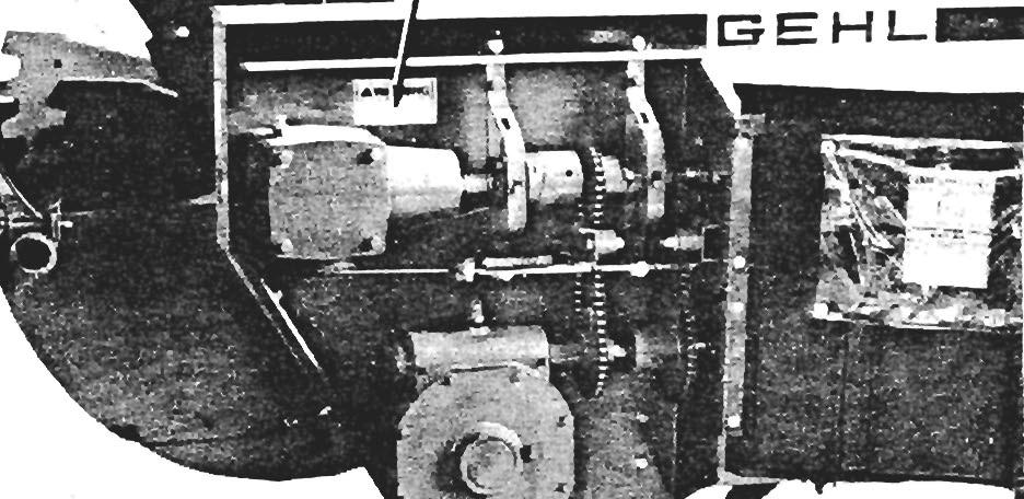
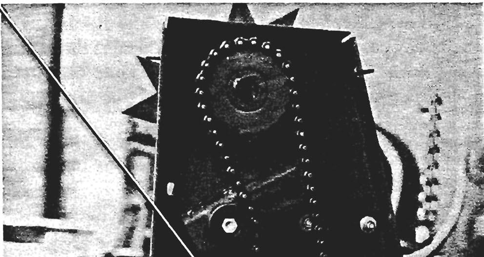
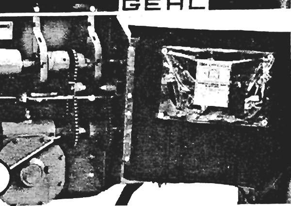
Apron Transmission Driven Sprocket (Fig. 6-6)
A 1/4 x 1 Grade 2 Shear Bolt and Locknut are provided in the Apron Transmission Driven Sprocket. Replacement 1/4 x 1 Shear Bolts and Locknuts can be obtained in packaged quantities of eight bolts and nuts by GEm... part number 900091. If the Conveyor Apron Drive Shear Bolt has sheared, exercise the MANDATORY SAFETY SHUTDOWN PROCEDURE (page 8) and rotate the Beater(s) backwards by hand, to align the holes for replacing the Bolt. If the Beater(s) can NOT be rotated, exercise the MANDATORY SAFETY SHUTDOWN PROCEDURE (page 8) and remove the Telescoping PTO Drive from the tractor PTO shaft to align the Shear Flange holes.
Main Drive Protection (Fig. 6-7)
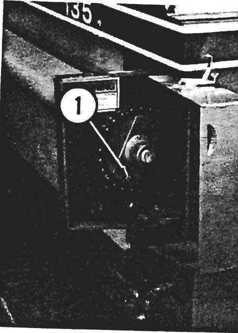
Replacement 1/4 x 1-1/2, Grade 8 Bolts and 1/4 Locknuts can be obtained in packaged quantities of eight bolts and nuts by GEHL ,part number 080079. If the Main Drive Shear Bolt has sheared, exercise the MANDATORY SAFETY SHUTDOWN PROCEDURE (page 8) and rotate the Beater(s) backwards by hand, to align the holes for replacing the Bolt. If the Beater(s) can NOT be rotated, exercise the MANDATORY SAFETY SHUTDOWN PROCEDURE (page 8) and remove the Telescoping PTO Drive from the tractor PTO shaft to align the Shear Flange holes.
1. PTO is being engaged at too high an RPM.
2. A foreign object is caught in Beater(s) or Beater is frozen tight.
3. Beater was NOT engaged when starting to unload. BE SURE to engage Beater after Spreader is unloaded and before starting to unload next load.
4. Beater(s) packed with manure.
Unplugging
Awarning
When any part of the Spreader becomes plugged, stop the unit IMMEDIATELY. NEVER leave the tractor seat to unplug the Spreader NOR attempt to climb Into the Spreader Box without first exercising the MANDATORY SAFETY SHUTDOWN PROCEDURE (page 8).
The following are probable causes for PTO Drive Shear Bolt failure:
If the Spreader becomes plugged, the area ahead of the Beater(s) will probably have to be unloaded with a pitch fork so that the Beater(s) are free to rotate. After unplugging, replace any Bolts which may have sheared and BE SURE that the Control Indicator is in the . "Start/Slow" position BEFORE restarting the tractor and engaging the PTO.