2 minute read
CHAPTER 7 ADJUSTMENTS


A Caution
BEFORE proceeding to perform any adjustments on the Spreader, exercise the MANDATORY SAFETY SHUTDOWN PROCEDURE (page 8).
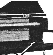
APRON CHAIN TENSION (Fig. 7-1 & 7-2)
Apron Chain tension should be checked after every 50 hours of operation. Apron Chain tension is important because too much slack will cause the Chain to ride off the Sprockets and, too much tension will cause premature wear and early failure of the Chain and/or Sprockets. Adjust the Take-up Bolts, on both front comers of the Spreader Box Frame,evenly until the Chain is 1/2" (13 mm) from the Channel Crossmember at the rear of the Spreader.
APRON DRIVE TRANSMISSION INPUT (Fig.
7-3)
Chain Tension Blocks are provided for the Drive Chains on the Apron Drive Transmission. Chain tensions should be checked after every 50 hours of operation. Chain tension is adjusted by loosening the Bolt and adjusting the Block position on either Chain.
NOTE: In freezing temperatures, BE SURE to keep the Box Floor and Apron Chain Slats clean. Operate the machine empty (before loading) to make sure nothing is frozen tight.
1 • Chain Tensloner Blocks
2 •
Fig. 7-3: Apron Drive ChaIn Adjustment Detail

MAIN DRIVE CHAIN (Figs. 7-4 & 7-5)
The Main Drive Chain, located in the front of the Spreader, is provided with a Chain Tightener Block. To adjust Chain tension, remove the Front Cover and adjust the position of the Block until the proper Chain tension is obtained. Chain tension should be checked after every 50 hours of operation. The Chain is properly tensioned when it can be deflected approximately 1/4 to 1/2" (6 to 13 mm), with hand pressure applied at the midpoint of the Chain, between the Drive and Driven Sprockets.
SHIFT MECHANISM (Figs. 7-6, 7-7 & 7-8 in the "Start" position, the Beater Clutch should & see Figs. 7-3 & 7-4) be fully engaged, the 2nd Speed Clutch Jaws should be disengaged (approximately 1/16" or To obtain the proper shifting adjustment, follow this 1.6 mm Gap) and, the Shift Cable should have procedure: some slack in it as shown.
1.
1 • ShIft Cable (NOT Taut)
2 • Beater Clutch Jaws Engaged
3·1/16" (1.6 mm) Gap
4 • 2nd Speed Clutch Jaws Disengaged
1 - Shift Cable
2 • "0" Clearance)
3 • 2nd Speed Clutch Jaws Fully Engaged
4 - Compression Spring
5 • Front Sliding Pivot
6 - Washer
Fig. 7·7: Beater Clutch "Fast" Position Adjustment Detail
2. Referring to the Beater Clutch "Fast" Position if it is loose. the Cable will have to be adjusted Adjustment Detail, move the Front Shift Lever to longer until the Washer is tight. the 2nd Notch ("Fast") position. Adjust the Cable length, on either end as required. so that the 2nd Speed Clutch just reaches the point of full engagement and the Compression Spring is still maintaining tension on the Washer and holding it against the Front Sliding Pivot. This will be evident when there is "0" clearance between the 2nd Speed Clutch Jaws. Check the indicated Washer;
1·1/16" (1.6 mm) Gap
2 • Beater Clutch
3· Washer
4 • Rear Sliding Pivot
3. Move the Front Shift Lever to the "Cleanout" NOT, repeat step 2 and then, recheck the Clutch position. If the adjustment was properly done in adjustment. If the 1/16" (1.6 mm) Gap can NOT the preceding step 2, the Beater Clutch should be be attained, it may be necessary to add Washer(s) disengaged with approximately 1/16" (1.6 mm) between the Rear Sliding Pivot and Roll Pin to gap between the Jaws as shown in the Beater increase the Gap or Washer(s) may have to be Clutch "Cleanout" Position Adjustment Detail. If removed to reduce the Gap.
1 - Shift Cable
2 - Threaded Stud
3 - Adjustment Bracket
4- Indicator Lever
4. Referring to the Indicator Lever Cable Adjustment Detail, use the Threaded Stud for "fine" adjustment of the Shift Cable or reposition the Adjustment Bracket to a different hole location for a larger "coarse" adjustment.