5 minute read
C Transport


1 Safety regulation for transportation
Accidents can happen when the paver and the screed are not properly prepared for transportation or when transportation is carried out improperly!
Reduce both the paver and the screed to their basic widths. Remove all protruding parts (such as the automatic leveling system, auger limit switches, aprons, etc.).
When transporting under a special permit, secure these parts!
Close the hopper lids and engage the hopper transport safeguards. Lift the screed and engage the screed transport safeguards. Convert the protective roof (if equipped) and engage the latch.
Check that the clamping device for the auger crossbeam is fastened and that the telescopic tube cannot slide out (see chapter E, section 1.5).
Pack all parts that are not permanently fixed to the paver and the screed into the appropriate boxes and into the hopper.
Close all coverings and check that they are securely seated.
When loading using ramps, there is a risk that the machine will slip, tilt or overturn. Drive carefully! Keep people away from the danger area!
Additional stipulations for transportation on public roads:
Depending on local regulations, tracked propelled paver must not be driven as self -propelling vehicles on public roads.
Note the different state and local regulations.
The operator must be in the possession of a valid permit for vehicles of this type.
The operating panel must be moved to the side of the oncoming traffic and secured in this position.
The driving lights must be properly adjusted.
Only attachments and extension parts may be transported in the hopper, no material!
If necessary, the operator must be assisted by a second person when driving on public roads –especially at road crossings and junctions.
2 Transportation on low-bed trailers
Reduce the paver and the screed to their basic widths; also remove any attached side plates. The maximum approach angle is indicated in the section entitled “Technical Data”!
Check the fill level of the operating fluids so that these do not escape when driving on an incline.
Attachment and loading equipment must meet the federal, state and local safety regulations!
The weight of the paver must be taken into consideration when selecting the attachment and loading equipment!
2.1 Preparations
- Prepare the paver for transportation (see chapter D).
- Remove all overlaying or loose parts from the paver and screed (see also operating instructions for the screed). Store these parts in a safe place.
- Move the paver to the uppermost position if necessary.
Step Operation
1 - Select the master console.
2 - Close the hopper lids.
3 - Engage both hopper transport safeguards.
4 - Lift the screed.
5 - Retract the screed to the basic width of the paver.
6 - Engage both screed transport safeguards.
7 - Lift the auger.
8 - Turn the ranage shift selector to zero.
9 - Turn the travel speed preselecting regulator to zero.
10 - Move the drive lever forward.
11 - Extend leveling cylinders completely.
12 - Set the drive lever to the center position
2.2 Driving onto the low-bed trailer
Make sure that there are no person in the danger area during loading.
- Use the work gear and low engine speeds to drive onto the low-bed trailer.
- Lower the screed onto wooden blocks on the low-bed trailer.
- Turn the switch off.
- Attach and secure the protective hood to protect the operating panel.
2.3 Secure the paver to the low-bed trailer
- Use only proper and permitted load fastening devices.
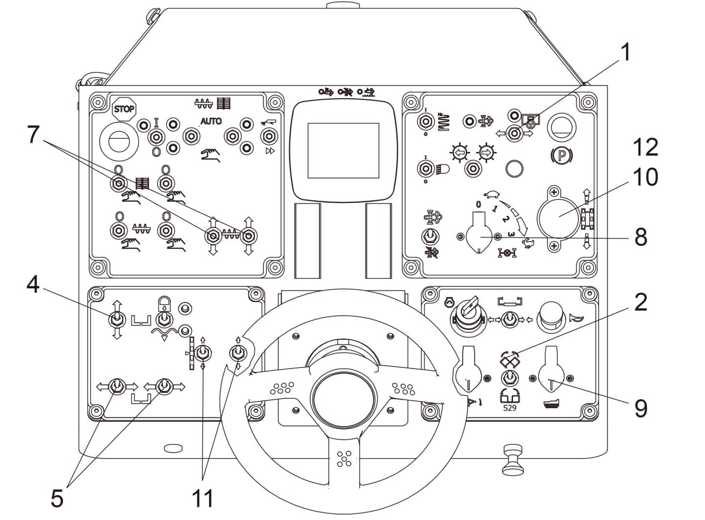
- Use the four tie-down points provided (1, 2). These points have a tie-down limit of 10,000 lbs. (3545.9 kg) each.
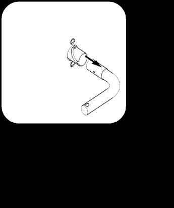
- Wait until the exhaust extension pipe has cooled down; then swing and secure it.
2.4 After transportation
- Remove the chains, hooks and all other transport tie-down tools.
- Swing the exhaust extension pipe up and secure it.
- Lift the screed to the transport position
- Start the engine and drive from the trailer at a low speed.
- Park the paver in a secure spot, lower the screed and switch the engine off.
- Remove the key and cover the operating panel with protective hood, then secure it.
3 Transportation
Reduce the paver and the screed to their basic widths; also remove any attached side plates.
3.1 Preparations
- Prepare the paver for transportation (see chapter D)
- Remove all overlaying or loose parts from the paver and screed (see also Operating Instructions for the screed). Store these parts in a safe place.
Step Operation
1 - Select the master console.
2 - Close the hopper lids.
3 - Engage both hopper transport safeguards.
4 - Lift the screed.
5 - Retract the screed to the basic width of the paver.
6 - Engage both screed transport safeguards.
7 - Lift the auger.
8 - Turn the ranage shift selector to zero.
9 - Turn the travel speed preselecting regulator to zero.
10 - Move the drive lever forward.
11 - Extend leveling cylinders completely.
12 - Set the drive lever to the center position
Step Operation
1 - Turn the selector to position 3.
2 - Turn the pre-selecting regulator to its maximum point.
3 - Use the drive lever to regulate the speed.
Press the emergency stop button when an emergency situation arises!
Use only lifting gear that can bear the load. (See chapter B for weights and dimensions).

Attachment and loading equipment must meet the conditions of the applicable accident prevention regulations!
Depending on the type of screed used, the paver ’s center of gravity, with the screed mounted, is located in the area of the drive unit’s rear reversing roller.
- Secure vehicle wherever it is parked.
- Engage the transport safeguards.
- Remove any attachments and extension parts from the paver and the screed until the basic width has been attained.
- Remove all protruding or loose parts of screed and machine.
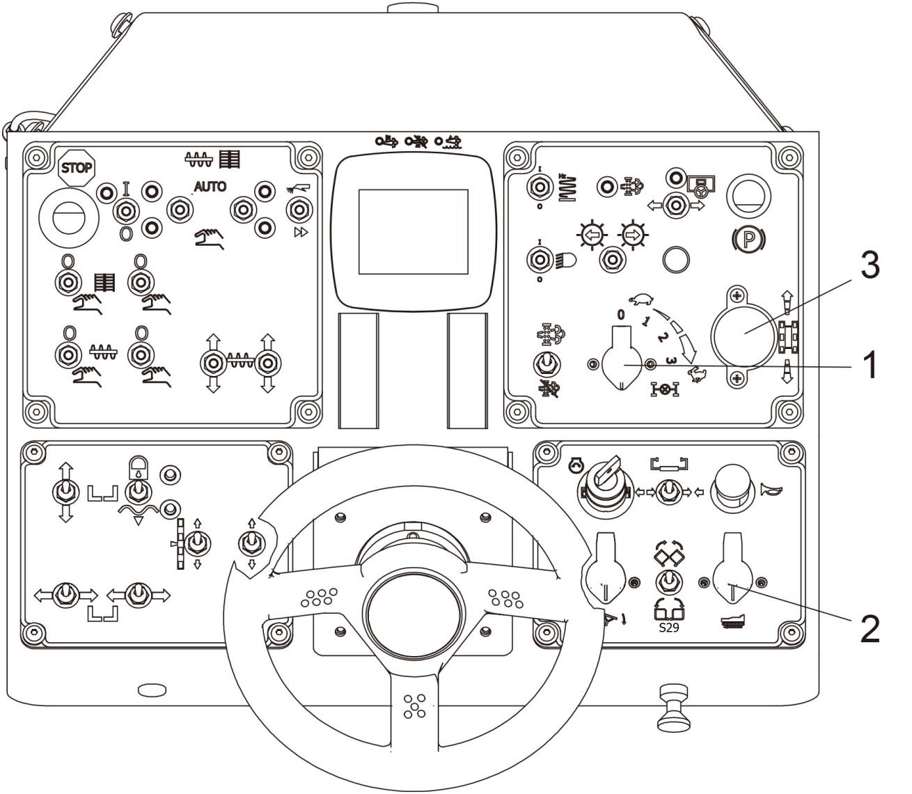
- Attach lifting gear to the four attachment points (1,2).
The max. permissible attachment point load is.
Attachment point (1): 20,000 lbs. (9071.9 kg) each for a total of 40,000 lbs. (18144 kg)
Attachment point (2): 20,000 lbs. (9071.9 kg) each for a total of 40,000 lbs. (18144 kg).
Make sure that the paver is secured in a horizontal position during transport!
Follow all reg ulations and apply all safety measures applicable for towing heavy construction machines.
T he towing vehicle must be capable of securing the paver, even on slopes.
Use only approved tow bars!
If necessary, remove any attachments and accessories from the paver and the screed until the basic width has been attained.
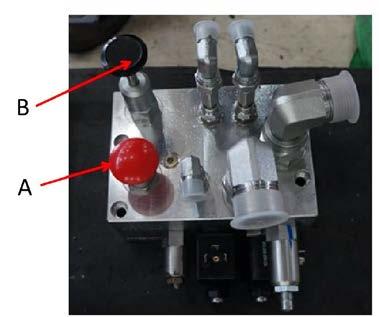
A hand pump is located in the eng ine compartment (left) that must be activated to be able to tow the machine
Pressure f or releasing the track drive system brakes is built up with the hand pump.
Do not release the track drive system brakes until the machine is sufficiently secured against accidental rolling or is already properly connected to the towing vehicle.
- Pull the Handle(A) and turn the handle 90 and release Handle(A) to the DOWN position.

Pump the Handle(B) of the hand pump up and down until sufficient pressure has been built up for the track drive system brakes to release.
Now caref ully and slowly tow the paver out of the construction area. The maximum towing speed is 2mph (3 2 k ph)
Always tow the machine the shortest distance to the means of transport or the next parking opportunity. After towing, return the Pump Pressure Lock and Release Handle (2) to the UP position. This will release pressure in the Hand Pump and will allow the braking system to engage. The track drive system brakes are now reactivated and the machine is secured against rolling
6 Safety parking the vehicle
When the paver is parked at a location accessible to the public, it must be secured in such a way that unauthorized persons or playing children cannot damage the vehicle.
- Remove the ignition key and main switch (1) and take it with you – do not hide them somewhere on the machine.
- Protect the operating panel with the dust cover and lock it.
- Store parts and accessories in a safe place.

Do not turn the main switch off until 100 seconds after the ignition has been turned off! The engine electronics require this length of time to back up data, and such device can prevent the engine’s electronic control module (ECM) from sustaining damage and battery discharging.