5 minute read
F 6.0 Maintenance – Hydraulic System


1 Maintenance – hydraulic system
-
-
-
-
-
- High pressure filter
Check the maintenance indicator
- High pressure filter
Replace the filter cartridge
- Pump distribution gear
Check the oil level
- Pump distribution gear
Fill with oil
- Pump distribution gear
Oil change
- Hydraulic hoses
Inspect hoses
- Hydraulic hoses
Replace the hoses Maintenance Maintenance during
1.2 Hydraulic System
A paving machine has many components and implements that are controlled by a hydraulic system, either directly or indirectly. Before working on or inspecting any part of a paving machine, it is important that the individual knows how the components move and are controlled by the hydraulic system components including the respective control circuits
Before working on or inspecting any component, it must be physically constrained from any movement that could cause injury to the worker. The worker must be alert to not placing any part of his/her body where movement of a component could cause injury, unless that component is physically contrained from movement, if the hydraulic system fails, is disconnected, or is asignaled to cause movement
It must also be recognized that there are occasions where component and or vehicle movement may react to the release of potential energy. Where applicable it must be confirmed that all measures are employed to ensure that any and all sources of potential energy are released and/ or physically restrained
All tramming, hopper and conveyor functions and augers are hydraulically powered. The hydraulic system consists of a 50 gallon (189.21 liter) hydraulic reservoir with a 10 micron filtration system. The propel pumps, conveyor and auger pump, generator pump and screed functions are driven by the pump drive gear box which is mounted directly to the engine. The hydraulic system includes various motors, cylinders, valves, filters and hose piping. A hydraulic oil cooler assures optimum oil temperatures to maximize system efficiency and component life
1.3 Points of maintenance
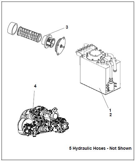
Hydraulic oil tank (1)
- Oil level check at the sight level gauge (A) on the side of the tank.
NOTE:
View the sight level gauge by the opening tank flap on the L.H. side of the machine.
With the cylinders fully retracted, the oil level should at the upper mark.
To add oil:
- Remove cap (B).
- Add oil through the fill port until the level shows full at the sight level gauge (A).
- Return cap (B).
NOTE:
Use only the recommended hydraulic oils – see section “Recommended hydraulic oils”.
To change the oil:
- To drain the hydraulic oil unscrew the drain plug (C) at the bottom of the tank
- Collect the oil in an appropriate container using a funnel

- After draining, add a new seal ring and then screw the plug back into place
Hot oil or components can burn. Oil must be at normal temperature when draining. Avoid contact with hot oil or components.
Gearbox must be filled with fresh, clean oil.
Always change the hydraulic oil filter(s) when changing the hydraulic oil.
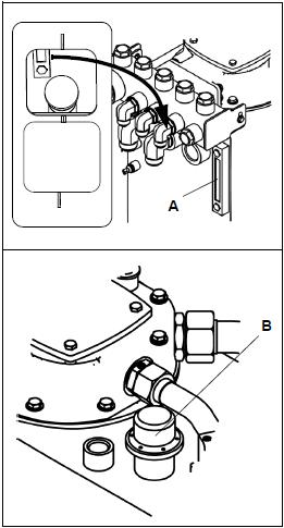
Suction / return flow hydraulic filter (2)
Change the filter at the intervals specified or when the maintenance indicator (A) is at the red mark or when changing hydraulic oil. When inspecting the maintenance indicator, the hydraulic oil must be at least 175°F (80° C)
When changing the hydraulic oil also change the filter.
- Remove the lid fastening screws (B) and remove the lid
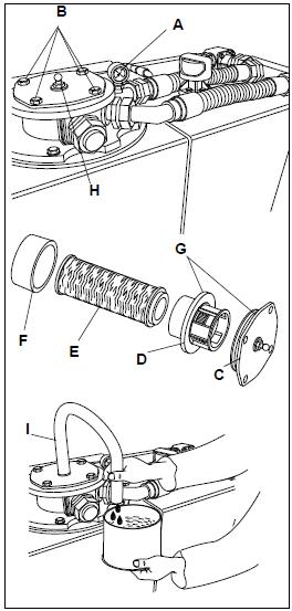
- Disassemble the withdrawn unit into the following parts
- Lid (C).
- Separating plate (D).
- Filter (E).
- Dirt collection cage (F).
- Clean the filter case, the lid, the separating plate and the dirt collection cage
- Check and replace the O-rings (G) when required.
- Wet the seal surfaces and the O-ring with clean fuel
Venting the filter
- Fill the open filter case with hydraulic oil to just below the upper rim.
- Should the oil level drop, fill with oil.
The oil level slowly lowering by about 1/4 in. /min. (1 cm/min) is normal!
- When the oil level remains steady, mount the assembled unit with the new filter cartridge, carefully into the housing and tighten the locking screws of the lid (B).
- Open the vent screw (H)
- Mount a transparent hose (l) on the vent screw and lead it into an appropriate container.
- Start the engine and run it at idle speed
- Shut-off the bleeding screw (H) as soon as the oil discharged through the hose is clean and free of air bubbles.
The process from mounting the filter lid until starting the engine should take place within 3 minutes or the oil level will drop too much in the filter case.
Check the seal after changing the filter.
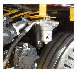
High pressure filters (3)
Replace the auger charge filter (A) cartridge and conveyor pump / work system filter (B) when the maintenance indicator on top of the filter cartridge head turns “red”.
- Unscrew filter housing.
- Remove the filter cartridge.
- Clean the filter housing.
- Insert the new filter cartridge.
- Replace the seal (O-ring) on the filter housing.
- Screw the filter housing on by hand, then tighten it using the appropriate tool.
- Test the filter for tightness and leaks.

Always replace the seal (O-ring) whenever the filter cartridge is replaced.
After the filter cartridge has been replaced, the indicator on top of the filter cartridge head will return to “green”.
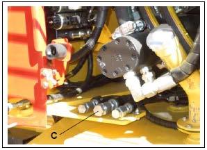
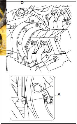
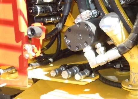
Pump distribution gear (4)
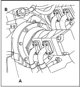
- Check the oil level at the sight glass (A) (at the side of the distribution box).
NOTE:
The oil level must be up to the center of the sight glass.
To add oil:
- Unscrew the plug (B).
- Add oil until the sight glass (A) shows the correct fluid level.
- Return and tighten the plug (B).
Keep the work area clean!
Hot oil or components can burn. Oil must be at normal operation temperature when draining. Avoid con- tact with hot oil or components
Gearbox must be filled with fresh, clean oil
Change the oil when the engine is at operating temperature.
- Place the end of the hose in an appropriate container and catch the oil.
- Open the shut-off valve and let the oil drain completely.
- Shut off the valve, remove the hose and return the cover cap.
- Add only approved oil to the distribution box (B) until the oil level is at the center of the sight glass (A).

Hot oil or components can burn. Oil must be at normal operation temperature when draining. Avoid contact with hot oil or components.
Hydraulic hoses (5)

Frayed or damaged hoses can break instantly causing hot hydraulic fluid to spray causing severe burns. Always replace worn or damage hoses immediately
Hot oil or components can burn. Oil must be at normal operation temperature when draining. Avoid con- tact with hot oil or components.
- Check the condition of the hydraulic hoses carefully.
- Immediately replace any damaged hoses.
Old hoses may become porous and burst! Hot oil spraying from a burst hose can cause severe burns!
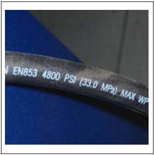
Each hose has the maximum pressure allowed for that hose printed on it
Do not use hoses that have been in storage for a long time. Check for the proper pressure rating printed on the hose.