4 minute read
D 3.0 Operation


1 Operating elements on the paver
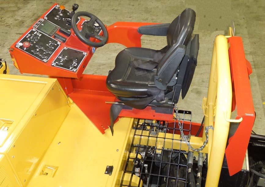
Operator ’s platform
Seat console
The seat console can pivot beyond the outer edge of the vehicle, providing the driver with a better view of the paving area in this position
- Release the platform lock (1)
- Swing the seat console to the desired position
- Engage the lock into one of the fixed positions (2)
After locking the seat console, check it to ensure it will not move into another position!
Dust cover
The dust cover (3) can be stored on the bar (4) behind the seat
To avoid injury, the individual seat settings should be checked and adjusted before starting the vehicle
After the adjustments are set, check the seat to ensure it does not move out of adjustment.
- Seat forward and back adjustment (1): The seat can be moved forward or it can be moved back to adjust the seat; raise the lever on the lower left side of the seat to release the lock. Once the seat is in the desired position, release the lever and the seat will lock into place.
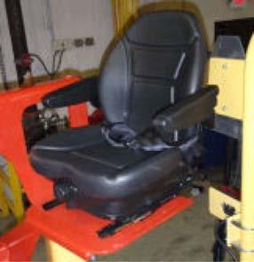
- Seat back rest adjustment (2): The back rest can be adjusted to lean forward or lean back. To adjust the back rest, turn the knob on the lower front part of the seat. Turn the knob clockwise to lean the back rest forward; turn the knob counter-clockwise to lean the back rest back
- Armrest positions (3): The armrest can be lowered to support the arm or it can be raised to be stowed out of the way.
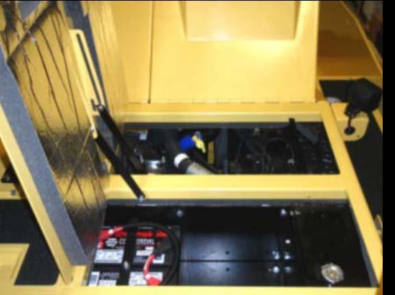
Batteries
The batteries are located under the right hand side (from operator platform) maintenance door
There are two 12 V batteries to produce the 24V needed for the electrical system.
For servicing, see chapter F.


Follow the instructions when jump starting the paver. (See section D 4)
Batteries
Battery main switch
The main switch interrupting the circuit between the battery and the main fuse is located above the battery pack.

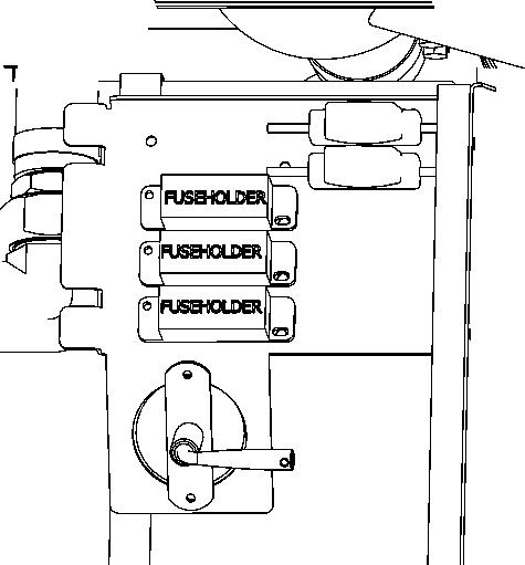
See chapter F for fuse locations and fuse order
- To switch the ignition off, turn the key (1) to the left and pull it out
Do not lose the key. Without it the paver can no longer be moved!
Do not turn the main switch off until 100 seconds after the ignition has been turned off! Lock the service doors/covers.
- To prevent the engine’s electronic control module (ECM) from sustaining damage.
- To avoid battery discharging.
- To make it difficult for unauthorized persons to start and operate the machine.
Before parking or transporting the paver, the hopper halves must be pivoted upwards and the trans- port safeguards for the hopper must be inserted.
- Before parking or transporting the paver, the hopper halves must be pivoted upwards and the trans- port safeguards for the hopper must be inserted
- Without transport safeguards inserted, the hopper halves will slowly open; danger during transportation.
Do not enter the hopper while the engine is running! Danger of being caught by the conveyor
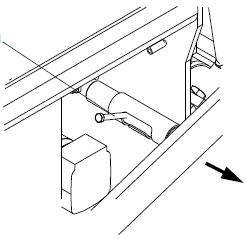
Mechanical screed transport safeguard (to the left and the right beneath the driver ’s seat)

Used to protect the lifted screed from inadvertent lowering. The screed transport safeguard must be inserted before transportation and when work is finished
- Lift the screed.

- Activate the levers (1).
- Check that the safety (to the left and to the right) engage under the crossbeams.
Transportation with an unsecured screed bears the danger of accidents
Insert screed lock only at crown adjustment “zero“! Lock the screed only for transportation. Use the lock for transportation only! Do not enter or work under screed if it is only secured with the screed locked for transportation
Paving thickness indicator
The Paving Thickness Indicator scales are located on the left and right sides of the vehicle.
- The Paving Thickness Indicator (1) shows the setting on the Scale (2)
- In normal paving situations, the same paving thickness should be set on both sides of the vehicle!
Avoid different settings on the scales as this will produce un-even pavement
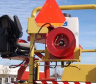
Release Agent System
Used to spray the parts coming into contact with asphalt with a separator emulsion
NOTE: Check local regulations concerning use of cleaners and use of solvents
- Pull hose (1) out of the guide until there is an audible click. The hose will lock in this position.
NOTE: The hose will retract automatically into the guide by pulling out until it clicks again, then it will reel in again
- On/off switch (2) for the emulsion pump
- Press hand-valve (3) to spray, release to stop spraying
- The spraying system is fed by the tank (4).


- (Only fill the tank when the machine is not moving.)
Switch on the spraying system only when the diesel engine is running; otherwise, the battery will be drained. Switch off after use.
Don’t spray into open flame or onto hot surface! Danger of explosion!
On/Off switch of working lights (1)

Toggle switch (1) to switch on all installed working lights
On/Off switch hazard flasher (2)
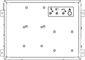
Activate switch (2) to switch on installed flasher
Warning Beacon
NOTE:
The function of the warning beacon must be checked daily before starting work.
- Place the warning beacon onto the plug-in contact and secure with a wing bolt (1).
- Slide the warning beacon with tube (2) to the desired height and secure with the both clamping screws (3).
NOTE:
The rotary warning beacon is easy to remove and should be stored securely when the work is done.
Conveyor limit sensors
The ultrasonic conveyor limit sensors control the material flow at the respective conveyor half. The conveyors should stop when the material has roughly reached the area below the auger tube NOTE:
This requires that the auger height has been adjusted correctly (see chapter E).
Ultrasonic auger limit sensors (left and right)
The limit sensors control the material flow at the respective auger half
The ultrasonic sensor is mounted to the side plate. Loose clamping lever for adjustment and modify angle / height of the sensor. The cables must be connected to the remote control units located at the sides of the screed
NOTE: Adjust the limit sensor positions while the material is distributed.
Socket 24V
Connect the working lights (24 V) or other devices here.
- Power is present when the main switch is switched on
NOTE:
As an option, one socket can be used to provide power for accessories