5 minute read
E 01 Set-up and modification


1 Special note on safety
Inadvertently starting the engine, the traction drive, the conveyor, the auger, the screed or the lifting units can be dangerous. Unless specified otherwise, work may only be performed when the engine is not running!
- To protect the paver against inadvertent starting: Set the drive lever to the center position and set the preselector to zero; if applicable, pull out the ignition key and the battery main switch
- Secure lifted machine parts (e.g. screed or hopper) against lowering by means of mechanical supports
- Replace parts or have them replaced as required
When connecting or disconnecting hydraulic hoses and when working on the hydraulic system, hot hydraulic fluid can escape at a high pressure
Switch the engine off and de-pressurize the hydraulic system! Protect your eyes!
- Mount all protective and safety devices before re-commissioning the paver.
- The walking platform must always reach over the entire width of the screed. The hinged walkway (optional for all variable screeds) may only be swung up under the following circumstances:
- When paving next to a wall or a similar obstacle.
- During transportation on a low-bed trailer
2.1 Height adjustment
Depending on the mix of materials, when working with layer thicknesses of up to 10 in. (25.4 cm), the height of the distribution auger (1) –measured from its bottom edge – should be around 5 cm (2 inches) above the material layer thickness (depending on its mix of materials).
Example:
Layer height 3 in. (7.6 cm)
Adjustment: 5 in. (12.7 cm) from the ground
An incorrect height adjustment can result in the following problems
- Auger too high:
Too much material in front of the screed; material overflow. When operating with larger widths, segregation and traction problems may occur
- Auger too low:
Not enough material that can be pre-compacted by the auger. Irregularities resulting from this cannot be completely compensated for by the screed (wavy surface). In addition, an increased wear on the auger segments occurs
2.2 Auger crossbeam – Hydraulic height adjustment
- Measure the set height of the auger crossbeam (left and right).
NOTE:
Equally press both switches/buttons (47) / (48) so that the auger beam stays level.
- Check whether the height on the left and on the right are identical
2.3 Auger extension
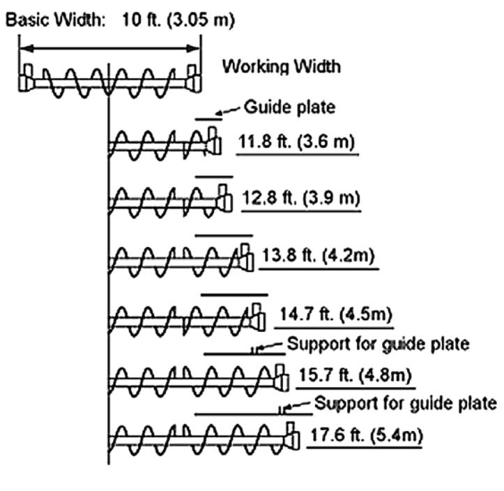
Depending on the type of screed, the most diversified working widths can be reached
Auger and screed extension must match. See the operating instructions for the appropriate screed, chapter “Set-up and modification”, especially:
- Screed extension chart
- Auger extension chart
To attain the desired working width, the respective screed extensions, side plates, augers, tunnel plates or cut-off shoes must be mounted
For widths of more than 11.5 ft. (3.5 m.), the auger should be fitted with extension parts on both sides to improve material distribution and to reduce the wear
The diesel engine must be switched off whenever work is performed on the auger as there is a danger of being pulled into rotating parts. This could cause severe injury or death
2.4 Mounting extension parts


- Loosen the clamping screws (6) on the support tube. Then turn in the center expanding screw (5) to expand the clamping.
- Pull the telescopic tube out of the support tube (7).

- Mount the required extension parts.
NOTE:
Observe the guide groove of the spline!
Make sure that the shaft end is clean!
- Install auger so pick end of auger is “IN TIME” with the discharge of the main auger. This is called “IN TIME” or “NORMAL” set up and is used to prevent segregation (or separation) of material. The auger pickup can be mounted 180 degrees away from the discharge. This called “OUT OF TIME” and is used with large or rounded stone to prevent segregation. If already mounted and segregation occurs in the mat at extension to main connection, move the auger pickup 180 degrees from the current position.
-
Before the clamping screws (6) can be tightened again, the expansion screw (5) must be sufficiently turned back!
Otherwise, the telescopic tube cannot be safely clamped and the splined shaft ends break.
When clamped insufficiently, the telescopic tube can slide out of the support tube and can cause severe injury or death as well as damage to the machine!
2.5 Mounting support tube extensions

If the working width exceeds 23 ft. (7.01 m.) an auger crossbeam extension must be mounted.
The support tube extension of the auger crossbeam consists of two halves (8) and is attached to the existing support tube by using a total of 5 screws. After the two halves have been screwed to the support tube, they also must be linked to each other by means of screwed connections


Clamping of the telescopic tube occurs by tightening the screwed connections (9) linking the support tube extension.
If the working width exceeds 14 ft. (6.26 m.) the hydraulic hoses (10) for the auger motors must be replaced with longer ones. These long hoses are included in the scope of delivery for this working width.
When connecting or disconnecting hydraulic hoses, hydraulic fluid can spray out at a high pressure and can cut or enter the skin
Switch the paver off and de-pressurize the hydraulic circuit! Protect your eyes!
When installing the hoses, make sure that the area around the connections is clean Any contaminants that enter the hydraulic system can cause damage to the hydraulic system.
2.6 Installing tunnel plates
To ensure an optimum material flow - especially in the case of large paving widths – so-called tunnel plates (11) must be installed. They are located directly in front of the auger distributor and – in conjunction with the auger – is an ideal system for conveying the material.
When operating with widths of more than 14.4 ft (4.4 m), two or more combined tunnel plates (13) must be used. In this case, additional stabilizing supports (12) must be attached to the telescopic tube.


The tunnel plates must be directly screwed to the receptacles provided for this purpose (14); they are located on the auger frame sides and can be adjusted in height.

Refer to the auger extension chart to determine which parts of the conveyor system are required for the desired paving width.
2.7 Installation additional braces
When operating with width of more than 25 ft. (7.62 m.) the augers must be provided with an additional support.
To do so, attach two braces on both the left-hand and the right-hand side, between the tunnel plate support and the bracket provided on the paver.
The braces are included in the scope of delivery for this working width.
3 Screed
The operating instructions for the screed explains what is required for mounting, setting up and extending the screed
4 Electrical connections
Ensure the following connections have been made once the screed has been mounted and set up.
4.1 Remotes from screed to paver
The screed plugs into the back of the paver socket (15). The paver and the screed communicate through this connection.
4.2 Right hand conveyor sensor control
The conveyor sensor connects to the DC control box. The control box is connected to the right remote by a cable through the rear bulkhead. The remote then sends the signal from the sensor to the paver thru the cable shown
4.3 Right hand auger sensor control
The auger sensor connects to the DC control box. The control box is connected to the right remote by a cable through the rear bulkhead. The remote then sends the signal from the sensor to the paver thru the cable shown.
4.4 Left hand conveyor sensor control
The conveyor sensor connects to the DC control box. The control box is connected to the right remote by a cable through the rear bulkhead. The remote then sends the signal from the sensor to the paver thru the cable shown.
4.5 Left hand auger sensor control
The auger sensor connects to the DC control box. The control box is connected to the right remote by a cable through the rear bulkhead. The re- mote then sends the signal from the sensor to the paver thru the cable shown.
4.6 Auger Chart