11 minute read
F 5.0 Maintenance – Engine


1 Maintenance – engine sub-unit
In addition to these Maintenance Instructions, the Maintenance Instructions of the engine manufacturer must always also be observed. All other maintenance work and intervals noted in these instructions are also binding.
1.1 Maintenance intervals
Maintenance Maintenance during run-in period
- Fuel
Check the filling
- Fuel tank
Refill with fuel
- Fuel tank
Clean the tank
- Engine oil system
Check oil level
- Engine oil system
Fill with oil
- Engine lube-oil system
Change the oil
- Engine lube-oil system
Oil filter change
- Engine fuel system
Fuel filter (drain the water separator)
- Engine fuel system
Replace the fuel pre-filter
- Engine fuel system
Replace the fuel filter
- Engine fuel system
Bleeding the fuel system
Maintenance Maintenance during run-in period
- Engine air
Check the air filter
- Engine air filter
Empty the dust collecting bin
- Engine air filter
Clean / Replace the filter cartridge
- Engine cooling system
Inspection the radiator fins
- Engine cooling system
Clean the radiator fins
- Engine cooling system
Check the level of the coolant.
- Engine cooling system
Fill with coolant
- Engine cooling system
Changing the coolant
- Engine cooling system
Check coolant level (additive concentration)
- Engine drive belt
Checking of drive belt
- Engine drive belt
Tightening the drive belt
- Engine drive belt
Replace drive belt
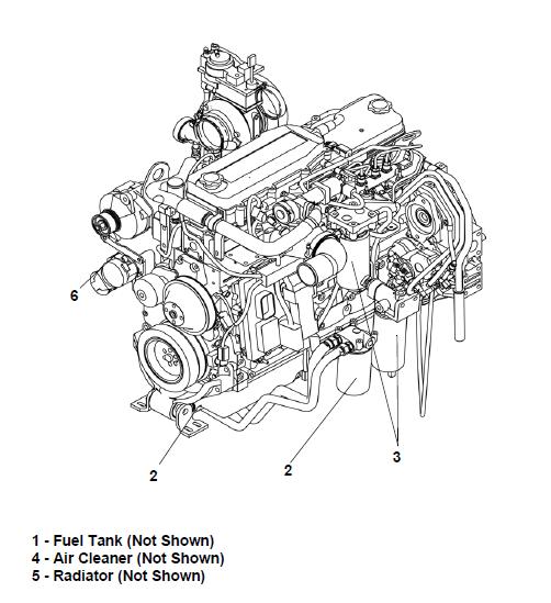
1.2 Points of maintenance
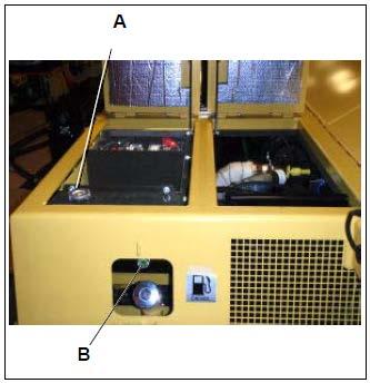
Engine fuel tank (1)
NOTE:
There is one fuel tank on each side of the machine.
- Check the fuel level on the operating panel (check display).
Fill the fuel tank before each work shift to prevent the fuel system of running dry. If the tank is ran dry, the system will have to be bled causing work delay
To add fuel:
- Unscrew cap (A) (under tank covers, r. h. paver side).

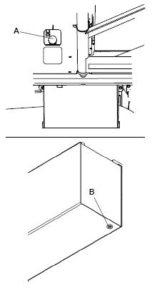

- Fill with fuel through the filler neck until the tank is full.
- Replace the cap (A).
- Repeat the process for the other tank.
Cleaning the fuel tanks:
- Unscrew the plug (B) at the bottom of the tank and drain about 1 qt. (1 L) of fuel into an environmentally safe collection pan.
- After draining, add a new seal ring to the plug and screw the plug back in place.
Repeat the process for the second fuel tank.
Engine lube-oil system (2)

Check oil level
Check that the oil level is between the maximum and minimum lines on the dipstick (A).

NOTE:
Check the oil level with the paver parked on a flat surface!
Some state and federal agencies in the United States of America have determined that used engine oil can be carcinogenic and can cause reproductive toxicity. Avoid inhaling vapors, ingestion and common prolonged contact with used engine oil. Do not allow used oil to drain into the ground. Always used proper procedures to dispose of the oil
To avoid personal injury, avoid direct contact of hot oil with your skin
If there is too much oil in the engine, the gaskets and seals may become damaged, while too little oil can lead to the oil overheating and damage to the engine.
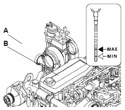
To add oil:
- Remove the cap (B).
- Add oil until the correct level is achieved.
- Return and tighten the cap (B).
- Check the oil level once again using the dipstick.
Oil change:
Do not drain the oil when the engine is cold. As the oil cools, suspended waste particals settle on the bottom of the oil pan. The waste particles are not removed with the draining cold oil. Drain the crankcase with the engine stopped. Draining the crankcase with the oil warm will allow the waste particles that are suspended in the oil to be drained properly.
Avoid contact with hot oil or components. Do not allow used oil to drain into the ground
There is a drain hose stored behind the left hand side flap.
- Place the end of the hose into a pan to catch the oil
- Remove the oil drain port plug (C) and let the oil drain
- Return the plug
- Remove the oil cap (B) and add only approved oil until the oil level reaches the full mark on the dipstick (A).
Changing the oil filter:
When changing the oil, mount the new filter after the used oil has been drained
- Remove the filter (D) located beneath the yellow plate and clean where the new filter installs.

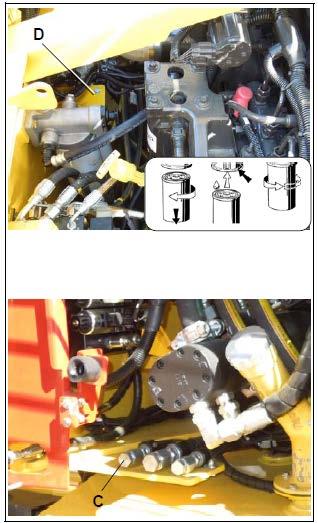
- Apply a thin coat of oil to the seal of the new filter and fill the filter with oil, then mount the filter and tighten by hand
Fill the oil filter(s) with clean lubricating oil before installation onto the engine. Lack of engine lubrication while the filter(s) are pumped full of oil is harmful to the engine
Engine fuel system (3)
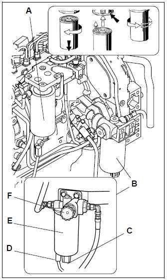
The fuel system consists of two filters:
- Pre-filter (A) with water separator (located in the engine compartment)
- Main filters (B)
Pre-filter – drain the water
Empty the condensation prior to every engine start or when the engine electronics indicate a fault.
- Drain the water at the drain valve (C), collect it, and then close the drain valve again.
Fuel leaked or spilled onto hot surfaces or electrical components can cause a fire. To help prevent possible injury, turn the start switch off when changing fuel filter or water separator elements. Clean up any spilled fuel immediately
Change the pre-filter:
- Drain the separated water at the tap (C), collect it, then close the tap again
- Remove the water detection indicator connection (D)


- Loosen the filter cartridge (E) using an oil filter wrench or oil filter strap and remove it.
- Clean the sealing surface where the new filter will mount.
- Apply a thin coat of oil to the gasket of the collection sump, mount it under the filter cartridge and tighten by hand
- Apply a thin coat of oil to the gasket of the filter cartridges, mount them under the holder and tighten by hand.
- Replace the water detector indicator connection (D).
- Unscrew hand wheel of the pump (F). Pump the hand wheel until the filter has filled with fuel
The system is filled with fuel when resistance at the hand wheel is noticeable during pumping!
- Screw in pump’s hand wheel (F).
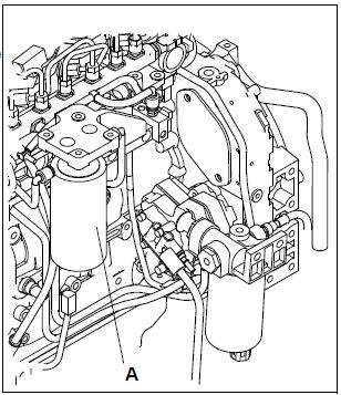
Main filter replacement:
- Loosen the filter (A) and clean the surface where the new filter will mount.

- Apply a thin coat of oil to the gasket of the new filter.
- Tighten the filter by hand
NOTE:
After mounting the filter, check it for proper tightness
Do not fill the fuel filters with fuel before installing them. Then fuel would not be filtered and could be contaminated. Contaminated fuel will cause accelerated wear to the fuel system parts
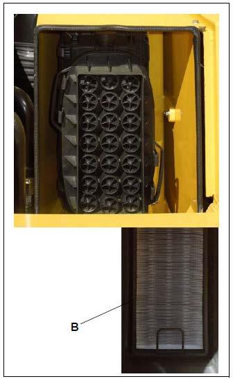
Engine air cleaner (4):
The function of the engine air cleaner is to filter the air taken into the engine through the engine’s air intake. The engine air cleaner is the dry type with two elements: a primary element that is cleanable and replaceable, and a safety element that should only be replaced and not cleaned. The assembly also includes a dust vacuator valve and an air cleaner indicator
NOTE:
Air intake filter pollution depends on the dust con- tent in the air and the mesh size of the filter selected
The maintenance of the filter becomes necessary if:
- The restriction gauge reads 25” H2O when the engine is stopped. This indicates that a restriction has occurred. This usually means the filters are dirty and requires opening the air cleaner and cleaning or replacing the elements

- When the engine electronic unit indicates service required.

Never leave the air cleaner open longer than necessary!
To remove the filter cartridges:
- Open the latches to remove the cover
- Remove the primary filter and then the filter cartridge (B).
NOTE:
Clean the filter cartridge and replace at least once per year.
- Blow out with dry pressure air (max. 30 psi / 2.07 bar) from inside blowing out. In case of urgency, tap the cartridge to remove dust
- Check the filter’s paper of the filter cartridge (by exposing to light) and inspect the seals. Replace them as required.
After completing the maintenance:
- Press the reset button (F) for the maintenance indicator (if equipped). The maintenance indicator is ready for operation
Engine Coolant system (5):
Fully formulated antifreeze must be mixed with quality water at a 50/50 ratio. A 50/50 mixture of water and ethylene glycol or propylene glycol antifreeze to fill the cooling system. The 50/50 mix gives protection to the cooling system at a range of 34_F ( 36_C) freezing point and a 228_F (110_C) boiling point, which is adequate for locations in North America. The actual lowest freezing point of ethylene glycol antifreeze is 68 percent. Using higher concentrations of antifreeze will raise the freezing point of the solution and increase the possibility of a silica gel problem
Do not remove the radiator cap from a hot engine. Wait until the temperature is below 120° F (50° C) before removing the pressure cap. Failure to do so can result in personal injury from heated coolant spray or steam. Remove the filler cap slowly to relieve coolant system pressure
Checking / filling coolant level
The coolant level is checked when the engine is cold. Check the coolant level daily (10 hours or as needed). Use a Refractometer to ensure the antifreeze and anti-corrosive liquid is sufficient (-25° F / -31.6° C)
- Add sufficient amount of coolant through the fill cap (A) on the coolant tank. Check the coolant level at the site-glass (B) inside the fuel fill door. Do not mix coolants. Only use Dynapac approved coolants.
Do not add cold coolant to a hot engine. Engine castings can be damaged. Allow the engine to cool to 120° F (50° C) before adding coolant
Changing the coolant
To change the coolant:
- Remove the radiator cap.
- Open the drain valve at the bottom of the radiator and drain the cooler into an environmentally approved drain pan with a capacity of about 5 gallons (19 liters)


- Inspect the hoses to and from the radiator and replace them if they look worn or cracked.
- Once drained, dispose of the coolant fluid in an appropriate manner
Coolant is toxic. Keep away from children and pets. Dispose of in accordance with federal, state and local environmental regulations.
- Close the drain valve.
- Fill the radiator with a 50 / 50 mix of water and ethylene glycol or propylene glycol antifreeze.
- Install the radiator cap.
- Start the engine and allow it to run a few minutes
- While the engine is running, check the radiator and hoses for leaks.
- When the engine coolant temperature reaches about 180°F (80°C), turn the engine off and check the coolant level again.
Checking and cleaning of the radiator fins
- If necessary, remove leaves, asphaltic oils and residue, dust or sand from the radiator.
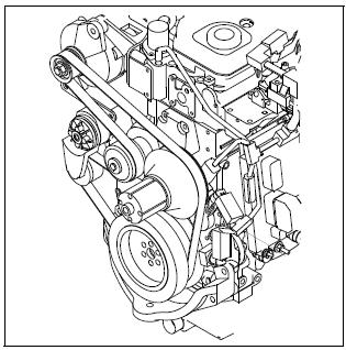
Engine drive belt (6):

Check drive belt / replacement.
Under normal operating conditions, the engine drive belt(s) should be inspected daily. Belt damage can be caused by incorrect size or length, pulley misalignment, incorrect installation, severe operating environment and oil or grease on the belt(s).
Adjust the belt tension in order to minimize belt slippage. Belt slippage will decrease the life of a belt. If the belt is too loose, the belt will vibrate. This vibration is enough to cause unnecessary wear on the belt(s) and on the pulleys. If the belt(s) are too tight, unnecessary stresses are placed upon the pulley bearings and upon the belts. These stresses will shorten the life of the belt(s) and the pulley bearings
To maximize the engine performance, visually inspect the belts for tension, wear, breaks, cracks or other damage. Replace the belts that are cracked or frayed. Adjust belts that have a glazed or shiny surface which indicates belt slippage. Correctly installed and tensioned belt will show even pulley and belt wear
Refer to the Engine Manual for proper procedure for removing and installing the belts
* Please refer Operation and Maintenance Manual from Engine manufacturer for the entire Engine maintenance interval and procedures
Maintenance – DEF tank
Clean the DEF tank
- Drain the tank.
- Remove the Multifunction Head Unit from the tank.
- Inspect the debris saturation of the DEF suction filter to determine if the filter needs to be replaced. If the filter is damaged or dirty, replace the filter.
- Rinse out the interior of the DEF tank using an ordinary hose or pressure washer.
- Rinse off the MFHU from top to bottom with low pressure, ensuring that all the debris has been removed.
- Reinstall the MFHU and the drain plug to fill the tank and verify no leakage occurs.
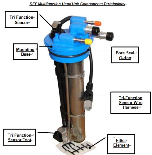
Multifunction Head Unit (MFHU) assembly
MFHU Removal:
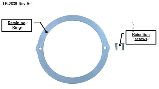
- Using a T25 Torx Driver, unscrew the retention screws that secure the Retaining Ring to the reservoir.
- Using a flathead screwdriver, gently pry around where the head unit is connected to the reservoir while simultaneously pulling on the top of the unit. Continue until DEF mounting base is free from reservoir.
- Pull the DEF head unit out until the bottom of the header is at the bottom of the tank bore.
- Angle the heel of Tri-function sensor foot upward and rotate the header until the bottom of the header is positioned inside the tank bore. When the bottom of the header is in the tank bore, fold the filter downward towards the interior of the tank. Continue to carefully remove the header out of the tank bore until completely freed.
MFHU Installation:
- Apply a thin layer of O-ring lubrication to the Bore seal O-ring
- Fold the Filter element in half towards the bottom of the Tri-Function Sensor. Tilt the header to an approximate 45˚ angle, with respect to the top of the tank. With the heel of the Tri-Function Sensor foot angled upward, place the filter edge and the toe of the Tri-Function Sensor into the tank bore. Gradually work the bottom portion of the DEF head into the Bore opening until completely inserted in the tank.
- Position the DEF head unit in the desired orientation and press on the top of the blue mounting base until it is completely seated in the tank bore.
- Position the retaining ring on Head unit and install the retention screws using the T25 Torx wrench. Recommended torque on screws is 20-30 in-lbs (2.26-3.38Nm)
DEF suction filter
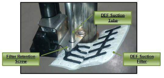
DEF Suction Filter is located at the bottom of the Multifunction Head Unit assembly thus requiring the head unit to be removed from the DEF reservoir.
Filter Removal & Installation:
- Locate the filter retention screw and remove using the T15 screw driver. Discard the screw.
- Pull the old filter off of the suction tube and discard.
- Position the new filter’s suction tube housing onto the bottom of the suction tube and press the filter flush against the bottom of the heater tube fin. Align the filter so the filter retention screw can screw into the retention screw housing.
- Install the retention new screw.
- Once the retention screw is installed, the MFHU will be ready to be installed into the tank.
Tri-function sensor
Sensor Removal & Installation:
- Loosen and remove the Tri-Function Sensor nut using a 1-5/8” box wrench or pliers. Set the Sensor nut to the side.
- Remove the sensor and spacer from the retention clips and slide the Tri-Function Sensor from the DEF head mounting base. A flathead screwdriver may be used to assist in wedging the sensor free from the clips.
- Inspect the new Tri-Function Sensor for signs of damage. Verify an O-Ring is located below the threading at the top of the sensor and should have Parker O-Ring Lubrication applied
- Feed the new Tri-Function Sensor cable into the bottom of the mounting base through the sensor opening. Press the Tri-Function Sensor into the retention clip with the foot of the sensor parallel with the Filter Element.
- Insert the spacer between the two retention clips and orient as seen in the image below.
- Position the top of the sensor through the mounting base such that the upper threaded portion of the sensor is seen. Ensure the top surface of the header is cleaned and install the Tri-Function Sensor nut on the top by feeding the cable through the sensor nut and screwing down the nut on the sensor down to the mounting base. T ighten nut to 40 in. lbs (4.5 Nm).
- Once the Sensor nut is installed the MFHU is ready to be installed into the tank assembly.