10 minute read
6.5Actual value calibration

from Dynapac Cold Planer PL 2000 S PL 2000 LS Operating Instructions Manual 900981225 - PDF DOWNLOAD

Digi-Slope sensor (transverse slope sensor)
During this process, the actual value display of both digital controllers is compared with the actual slope angle of the machine / milling drum
Initial situation for actual value calibration
-Sensors and controllers are fitted, all connection cables are connected.
-The machines is standing on as smooth and level the surface as possible, without any slope, and is smoothly lowered via the strut towers so that the milling drum is just above the ground.
-The side boards are lowered.
-The milling drum is activated, the diesel engine runs at idle speed.
-The scraper board is raised slightly and provides a clear line of sight to the rotating milling drum and the ground.
Other tasks
-Use the appropriate function switch on the side operating unit to lower the machine slightly more at the rear than the front without the rotating milling drum touching the ground.
-Use the buttons (7) to slowly and smoothly lower the left and right of the machine until the entire width of the rotating milling drum and the bit tips scratch against the base.
-Both side boards lie evenly on the ground, the machine is horizontal (front and rear at the same height).
-Switch the controller over to slope.
-The transverse slope symbol and an actual slope value of the grader / milling drum (in%) which deviates from the real slope value of the milled ground appear in the controller’s display window.
-The real slope value is calculated directly behind the milling drum box (in%) with the assistance of a highly accurate spirit level.
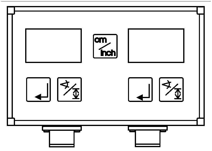
The information displayed on the optional actual value display can be changed over to slope at the touch of a button (A) so that the nominal height value can be displayed in the controller window.
The actual value calibration should be conducted on both controls one after another. Should the installation position of the Digi-Slope sensor have changed or should a controller have been replaced, a new actual value calibration must be conducted in both instances.
The actual value can be corrected at any time, i.e. even in automatic mode during milling.
Example: The controller value displayed is corrected to the value measured using the spirit level as follows:
-The A/M button is used to change over to manual mode, the „Auto“ function lamp is off. The display shows the actual value.
-Press and hold down the input key. „SET“ appears on the display, then the display changes again to the actual value.
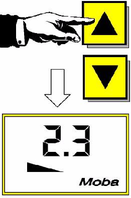
-The input key remains depressed and the actual value is corrected to the value required (example 2.3) using the UP/ DOWN buttons.
Height sensors
-By pressing the UP and/or DOWN button, together with the SET input key, the actual value (display value) can be changed in manual mode without the operating point being affected. This is done to correct the value displayed to the actual milling depth value
-This actual value correction can be made at any time, i.e. even in automatic mode during milling.
The information displayed on the optional actual value display can be changed over to height display at the touch of a button (A) so that the nominal height value can be displayed here.
6.6Other settings
-The levelling equipment is finely tuned to the machine. All parameters have been set perfectly and ensure perfect operation so that under normal circumstances the user will not have to make any changes to the pre-set values.
All values are checked again and changed if necessary when the machine is handed over/during machine instruction.
Should faults nevertheless occur, various key combinations can be used to access various menu items so that parameter settings such as:
-control precision level
-control width
-unit of measurement (centimetre, inch, foot)
-setting accuracy (transverse slope resolution in stages of: 0.1%; 0.05%; 0.02%) can be checked and reset.
Control window setting on digital controller
For effective milling operations, the control window is usually deactivated so that all milling depths required can be set directly and as quickly as possible. This may however result in the planer moving into dangerous positions if unforeseen events affect the milling depth setting and monitoring. For example, such events include:
-a height sensor suddenly loses its reference (e.g. the tensioned cable for Sonic-Ski during cable sensing or the cable sensor if the side board jams)
-if the transverse slope sensor has been set incorrectly (incorrect direction of slope) and the levelling equipment has been activated
-in automatic mode, the machine has been lowered from its upper position with the transverse slope sensor activated
In each of these instances, the movement of the machine must be stopped either by deactivating the levelling equipment or by pressing the EMERGENCY STOP button.
Safety can be enhanced by specifying the control width, thereby restricting any uncontrolled and undesired machine movement to a defined safe value. When using this operating variant, operators must however accept complicated and time-consuming operations. The earliest imaginable for milling operations with cable sensing would be setting the control window to a maximum of 6 cm.
6.7Operating the Moba-matic during milling
Initial situation for operation
-Sensors and controllers are fitted, all connection cables are connected.
-The zero value and/or actual value calibration has been conducted, the machine is in its operating position, all other settings required for milling have been conducted on the machine
-The A/M button is switched to semiautomatic mode (AUTO function lamp flashing)
-The nominal milling depth values and/ or the nominal slope value has been pre-selected.
6.8Other tasks for adopting the initial position for milling:
Milling with height sensors
Use switch(1) on rear side control panel to lower planer above rear strut towers until baseplates of side boards touch the ground in the rear section.
When starting to mill with offset (i.e. lower machine immediately to milling depth required):
2 6 5
Pult_PL2000LS_conv_RH_Top/PL2000LS_SBT_conv_rear_top1.wmf/Moba2.cdr/Moba29.jpg 3 4
When starting to mill without offset (i.e. lower machine gradually from zero to the milling depth required):
-When in semi-automatic mode, use the AB pushbuttons (1) on both digital controllers to set nominal value 0 (both controllers are jointly attached to one side of the machine). Use the „AM pushbuttons“ (5) on the main control panel (control lever (2), function switches (3) and (4)) and on the digital controller to activate the automatic function of the levelling equipment (function lamp AUTO (6) lights up) and lower the stationary machine to its zero height setting. When the feed starts, use AB pushbuttons (1) to slowly adjust the nominal value and then use function switch (7) on the rear side operating unit to „press“ the machine into the correct cutting position.
Milling with height sensors together with the transverse slope sensor
Initial position:
-The machine is lowered to the zero cutting depth position, the A/M buttons (1) of both controllers are switched to semi-automatic mode (AUTO function lamps (2) flashing).
-The lateral inclination sensor has been activated on the corresponding side of the machine by the controller.
-The UP / DOWN buttons (3) have been used to set the nominal values required (milling depth (here -8 cm), transverse slope (here 2.6% down to the right)) on the digital controls for the corresponding sides.
-Lower machine to milling depth
Risk of tipping!
The transverse slope sensor responds after the height sensor! To avoid dangerous inclines, never lower the machine out of its top position when the lateral inclination sensor is already activated. Instead, to do this, use both height sensors in automatic mode or lower the machine evenly using the manual adjustment facility, with the aid of function switches (4), (5), (6) on the rear side operating unit until close to the cutting depth required (note the direction in which it tilts!) Only then should the transverse slope sensor be activated.
7Operation
7.1Preparing for operation
Before first starting up
To protect the water system from corrosion and frost, it is filled with around 5-7 litres of antifreeze in the factory. Before first starting up the machine, this must be drained off, collected and disposed of in an environmentally sound way under due consideration of local rulings.
-Close shut-off valve (1).
-Unscrew filter housing (2) and drain.
-Open hoses on pumps (3) and run empty
Observe safety measures (gloves, protective goggles etc.)!
Devices and aids
To prevent delays and to ensure a problem-free flow of work, before starting work, operators should check whether all the devices and aids required for smooth operations are available.
A sufficient quantity of lubrication agents and fuel substances, tools, spare bits and other spare parts required as well as items of clothing for personal safety (protective clothing, reflective jackets, gloves, ear protection) should be available.
Before starting work
-Read safety instructions.
-Check personal protective equipment.
-The parts and equipment removed for safe keeping should be fitted again in accordance with the appropriate instructions.
-Walk around the machine to check for damage and leaks to ensure that the machine can be safely started.
-Conduct checks in accordance with „Checklist for machine operator“.
Checklist for machine operator
Once the maintenance and checking work listed in the maintenance manual has been conducted at the specified intervals, the inspections and control work listed in the following list should also be noted and conducted.
This work is used to assess the machine status and to assure perfect operations as well as personal safety.
If permitted by the operations in question, the checks should be conducted before, during and after use.
Any defects found should be rectified immediately in compliance with the safety regulations.
Check!How?
Emergency-stop button
-on main control panel
-on the side control units
Check with engine running: Engine must shut down immediately after actuation. The button engages and must be pulled out so that the engine can be started again.
Warning signal and warning information via display indicator
Horn
-on main control panel
-on the side control units
Reverse travel warning device
Lighting
-Operating headlight
-Rotary beacons
-Hazard flasher
Briefly press horn knob. Horn signal must sound.
Check with engine running. Acoustic signal must sound during reverse travel.
Lights must function, keep headlight glass clean.
Steering system
Check with engine running: Machine in straight ahead travel position, steering system responds in sync with the steering lever adjustment, uniform steering locks in all steering variants (when in co-ordinated steering mode and in crab steering mode, the rear axle does however respond with a slight delay).
Precise straightahead position of front and rear axles once the corresponding function switch has been pressed.
Traction unit - drive transmission
Check with engine running: Machine accelerates, hesitates and brakes smoothly both in the drive and working gear. When tracks encounter different levels of traction, anti-slip control responds (track in question slips briefly and then immediately rotates again at the speed of the other tracks).
Traction unit - strut towers
Check with engine running: Smooth extension and retraction.
Check with engine running: The limit switch opens when the drum flap is opened
Limit switch of drum flap milling drum and travel drives cannot be activated on the main operating panel.
-clutch of milling drum transmission disengaged, -belt tensioner relieved.
Belt tensioner
Drum flap
-Retaining and detent pins
Secure tensioning and releasing of powered belt when the engine is running as well as engagement and/or disengagement of the milling drum. Check bracket and seat of a centring screws.
Check with engine running: The drum flap opens and closes smoothly.
Both retaining pins can be slid in and out easily.
The detent pin automatically engages and locks the drum flap in its open position.
Check with engine running:
Side boards
Grab bars
-Raise evenly by pressing the switch until in the top position and automatically lower after releasing the switch
Check with engine running: Grab bars can be connected with detent pins when the side board is raised. When the upwards switch is pressed, the retaining bracket is automatically released from the detent pin.
Sliding shoe
Scraper
Upper conveyor
Check with engine running:
-Evenly extend and retract at full pressure by pressing the switch
-Evenly extend into floating position by pressing the switch.
Check with engine running:
-Evenly extend and retract at full pressure by pressing the switch
-Evenly extend into floating position by pressing the switch.
Check with engine running: Belt tension, forwards and reversing mode, smooth raising, lowering, swivelling.
Lower conveyor
Safety device
Water system
Weather protecting sun roof
Check with engine running: Belt tension, forwards and reversing mode
Fastening, check condition and function.
Check:
-Function of spray nozzles.
Check:
-Raising and lowering
-Locking mechanism
-Condition of roof and all-round panels.
Other equipment:
-Engine panels
-Lateral flaps
Check that panels and flaps are secure.
In addition to the tasks listed in the checklist, a visual check should be conducted of all components, equipment, functions. Note the condition, fastening and wear of individual elements, completeness and wear of milling tools as well as checking for specified settings, seal integrity and lubrication!
7.2Starting the machine
The following should be done before the diesel engine can be started and the machine can be operated:
-Daily machine maintenance.
Check the operating hours counter to determine whether further maintenance work should be conducted.
-Check the safety and protection equipment.
Check the position of the lever for changing over the upper conveyor.
If necessary, move the lever into operating position (1).
If necessary:
-Align and secure folding roof.
-Fold up ladder and secure.
-Open control panels and side operating units.
-Set up control panel (driver’s seat, operating panel, guardrails).
-Switch on battery’s main switch (2).
-Insert ignition key (3) into position „0“ in the ignition lock. When starting, no lights should be activated in order to conserve the battery.
-Switch on ignition (Item 1).
-Rotate ignition key to (position 2) to start the diesel engine.
Before starting, activate the horn by briefly pressing the horn button (4).
The vehicle cannot be started if the drive lever is not in the 0-position, if the emergency-stop button is pressed, or if the milling drum transmission or height adjuster are activated.
If the engine does not start straightaway, continue starting for a maximum of 20 seconds without a break, then wait 1 minute.
Undertake an auxiliary start if the battery is flat.
-Once the diesel engine has started up, release the ignition key.
-The ignition key will automatically jump back to position 1.
-Use the indicator lamps and display instruments to check the operating values. Correct if necessary.
-Allow the machine to warm up if necessary.
If the engine does not start straightaway, continue starting for a maximum of 20 seconds without a break, then wait 1 minute.