10 minute read
Water system

from Dynapac Cold Planer PL 2000 S PL 2000 LS Operating Instructions Manual 900981225 - PDF DOWNLOAD

The water system on the right-hand side of the machine comprises the following elements:
-Roller pump (1): to produce pressure --> water spraying system, cleaner 10 bar ( ).
-High pressure pump ( ) (2): to produce pressure --> high pressure cleaner 130 bar.
-75 micron upstream filter (3): The only filter used when the high pressure pump is not fitted.
-Additional 10 micron filter ( ) (4): Additional filter fitted when the high pressure pump is fitted.
-Pressure gauge for water pressure (5): Indicates the set water pressure.
Set water pressure to no more than 10 bar!
-Setting handle for water pressure (6): Adjustment range 0 - 10 bar.
-Vent lever (7): no function
-Tank water supply shut-off valve (8): to shut off the water supply from the tank, e.g. for maintenance work.
-Front shut-off valve- spray nozzles - milling drum box (9):
-Rear shut-off valve- spray nozzles - milling drum box (10):
-Shut-off valve- spray nozzle for lower conveyor (11):
When the cleaner ( ) is fitted, stop cock (9) for the front and rear spray nozzles on the milling drum box and stop cock (10) for the cleaner are also fitted! Shut off any connections not used and fit with blind plugs!
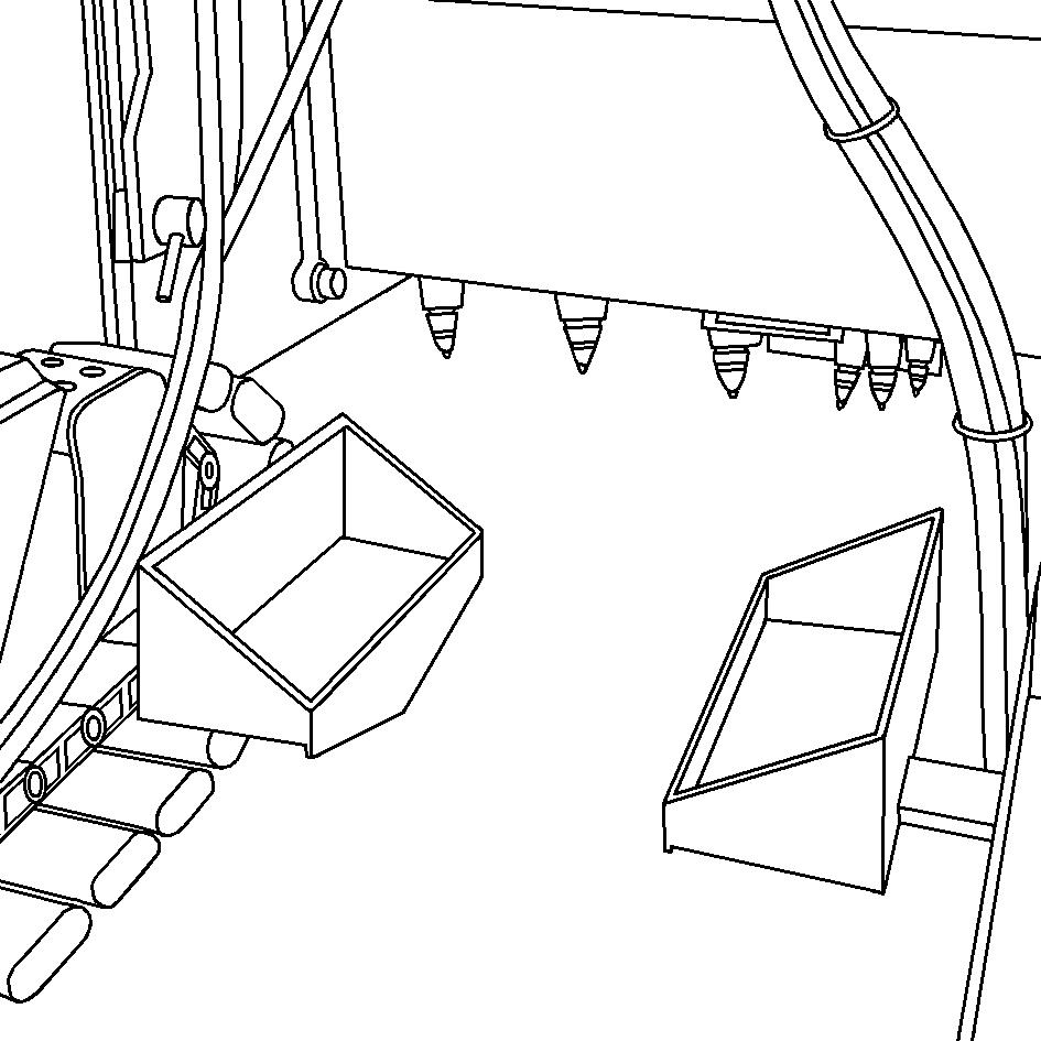
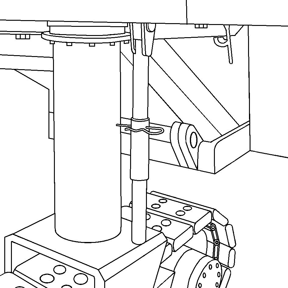
Cleaning system
The hose package (1) of the cleaning system is located on the underside of the vehicle frame at the rear of the machine. The spray pistol (2) is locked in its detent by a cotter pin (3).
-Remove cotter pin.
-Remove spray pistol from bracket.
-Pull hose out of fixture until you hear a click.
When released, the hose automatically engages here.
-The hose will automatically roll back up again if pulled and released again.
-The water jet is started by pressing the trigger (4).
When cleaning heavily contaminated areas, note that particles of dirt may be flung in all directions. Danger of accidents.
When undertaking cleaning work, never aim the water jet at electric components such as sensors, connection boxes, operating panels, electric distributors etc.!
4.2Controls, vehicle frame
Water tank gauge
The water tank can be equipped with two different types of gauge / level indicator:
-Sight glasses (1)
-Tube display (2)
Check the fill level of the water tank several times a day using the gauges / level indicators located on the sides of the tank.
Filling pump for water tank
The filling pump for the water tank is located at the front left of the machine.
To fill the water tank:
-unscrew seal cap (1) (if necessary use wrench)
-attach suction line and tighten
-start filling process by pressing switch (2)
-switch off filler pump as soon as desired fill level in water tank is reached (monitored by fill level indicator on water tank).
An overflow can be found on the underside of the machine. Excess water flows out through this if overfilled.
Ensure that the water is not too heavily contaminated because this may result in lengthy filter changes and cleaning work in the tank.
Water filling (pressure fill) connection for water tank
The connection (1) for the water tank’s pressure fill can be found on the rear underside of the machine.
To fill the water tank:
-open lock cock
-unscrew seal cap (if necessary use wrench)
-attach pressure pipe and tighten
-signal to the operator of the external filling pump that the filling process can be started
-switch off filler pump as soon as desired fill level in water tank is reached (monitored by fill level indicator on water tank).
-close the lock cock again before removing the filling hose.
An overflow can be found on the underside of the machine. Excess water flows out through this if overfilled.
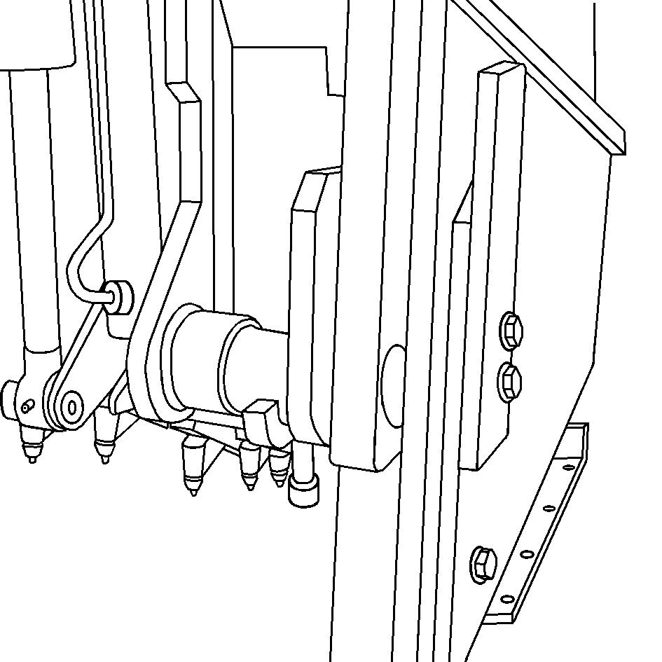
Changeover for separate circuits of rear strut towers
For some maintenance and repair work, the rear strut towers will have to be individually operated. The joint hydraulic circuit will have to be separated in such instances. The changeover equipment is located in front of the right strut tower under the engine hood.
To separately operate the strut towers:
-Raise machine to the height required and support.
-Remove retaining pin (1) and grip.
-Move changeover lever (2) in the direction required until locating bore (3) is under retaining pin (1).
-Allow retaining pin to engage.
-The chassis legs can now be moved separately using the appropriate switches on the rear side control panels.
Once maintenance and/or repair work is complete, turn the changeover valve back to its original position so that the chassis legs are moved together again.
Milling depth indicator
One milling depth indicator, indicating cm and/or inches, is located on both sides of the milling housing. This provides additional visual assistance in addition to the levelling equipment.
-The upper edge of the side board serves as a reference and indicates the depth of the engaged milling drum on the display (1).
Cutting edge points
Several control marks can be found on both side boards and, depending on the milling depth, indicate the extent to which the milling drum is engaged.
The control marks are used as assistance, e.g. if milling is to be conducted as close as possible to an obstacle (e.g. drain cover).
-Control marks are available for the following milling depths: 4 cm (1), 10 cm (2), 20 cm (3), 30 cm (4).
-The slots in the side board under the marks are used as a reference line and indicate the minimum possible distance between the milling drum and obstacle at which no damage will be caused.
Ultrasonic sensor on side board (optional)
One ultrasonic sensor (1) can be found above the side board on either side of the machine for height sensing of the side board.
If ultrasonic sensing is not required, the sensor can be removed.
-Unfasten connection cable (2)
-Unfasten wing screw (3), remove sensor.
The bracket can be folded to the side for transport or if the sensor is not being used.
-Remove interlock bolt (4)
-Swivel retaining fixture (5) to one side, allow interlock bolt to engage again.
Reflector on ultrasonic sensor
(optional)
There is a reflector (1) on the side board of each side of the machine. The reflector is secured directly to the side board and moves up and down with it.
The correspondingly shorter or longer measuring distance is detected by the ultrasonic sensor and acts as a reference parameter for the levelling equipment.
The reflected can be folded down for transport or if ultrasonic sensing is not being used.
-Remove wing screw (2), fold reflector down -Re-fit wing screw (2).
Interlock on moldboard
One interlock for the moldboard can be found on either side on the back of the drum box.
The interlock must be released before the moldboard can be opened.
When interlocked, the bolt (1) is in the detent bore (2).
Unlocking procedure:
-Use handle (3) to rotate interlock bolt upwards and slide towards the centre of the vehicle, via the sliding interlock (4).
-Rotate the bolt downwards so that the handle lies on the inner side of the sliding interlock (4).
Retaining hook of moldboard
The retaining hook for the moldboard can be found on the right-hand side of the machine.
When the moldboard is opened, this automatically engages in the retaining hook.
The limit switch is also activated
Only open the moldboard once the milling drum transmission and the travel drive have been switched off.
Refer to limit switch of moldboard
Unlocking procedure:
-Use the appropriate controls to open the moldboard so wide that the retaining hook is disengaged.
-Swivel retaining hook upwards on collar (1) and grip.
-Use appropriate controls to close the moldboard completely.
Limit switch of moldboard
The limit switch can be found behind the milling drum housing on the frame of the left-hand side of the machine.
The limit switch serves as a safety measure and is actuated as soon as the moldboard is opened.
Once the switch has been actuated, as an additional safety measure, the clutch and belt tensioner of the milling drum drive cannot be actuated and the machine cannot be operated.
For safety purposes, always ensure that the limit switch is functioning correctly!
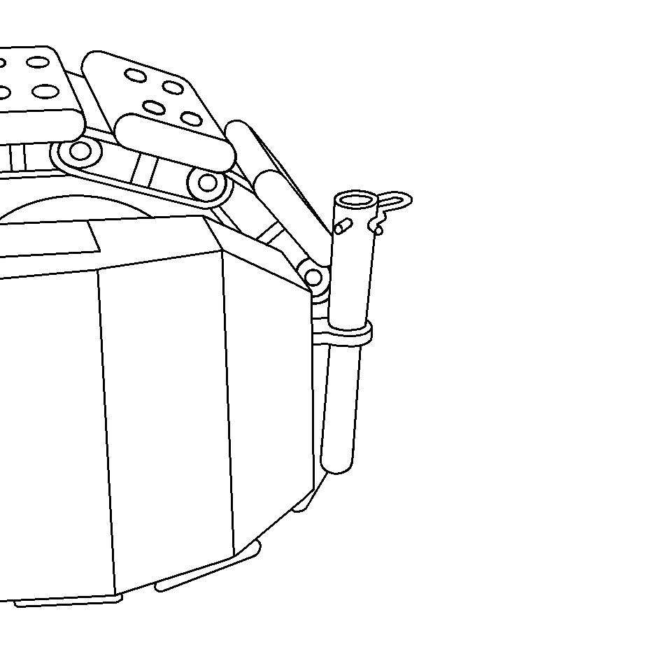
Service Supports
One separable service support can be found as a safety measure on every traction unit.
The complete service support is used for retaining purposes during maintenance and repair work.
In order to achieve a lower transport height, the upper section of the separable support is used on the trailer during transport.
The full length of the service supports should be placed under the machine during all maintenance and repair work.
If the machine is lowered unintentionally, wedge-shaped supports advance automatically into the recesses provided in the locating plates and therefore prevent the machine from being lowered further.
-Extend traction units to their maximum limit position.
-Remove complete supports (1) from the retaining tabs (2) and swivel down.
-If necessary, dismantle lower section (3) of support. Remove spring cotter pin (4) for this purpose.
-Ensure that the support is above the hollow of the support plate.
-For transport purposes and before starting work, return the supports to the retaining tabs.
Support brackets
If the lower sections of the service support have to be dismantled, there is a storage space inside traction units for them.
To prevent loss, always place the dismantled lower sections of the service supports (1) and corresponding cotter spring pins (2) in the support brackets (3) provided for this purpose.
„Moldboard function changeover“ valve
The valve for the raise and lower moldboard / swivel moldboard function changeover (1) can be found above the frame on the right-hand side of the machine behind the milling drum box.
-Switch position (1): raise / lower moldboard.
-Switch position (2): swivel moldboard (open/close).
Switch position (1) should only be selected for the working site, switch position (2) is used for maintenance and repair work.
Observe safety precautions when the moldboard is open.
„Upper conveyor function changeover“ valve
The valve for changing over between upper conveyor in operating position / upper conveyor in floating position function can be found on the left-hand side of the machine, in the front section of the inside of the frame.
-Switch position (1): upper conveyor in operating position.
-Switch position (1): upper conveyor in floating position (transport position)
Switch position (1) is for the working site and should be selected for transport tasks during which the upper conveyor is rigidly placed on the trailer, i.e. no swivel movements.
Switch position (2) should be selected for transport tasks during which the upper conveyor is flexibly mounted, e.g. placed on a support fixture on the tractor machine of the trailer.
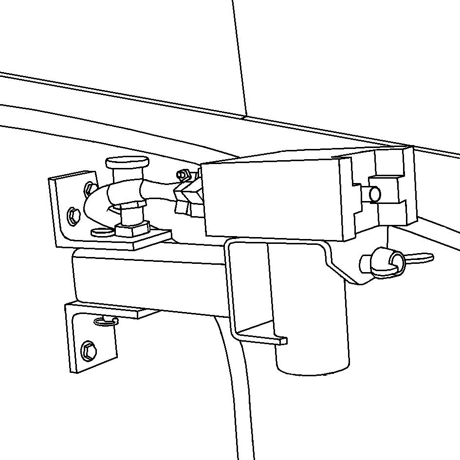
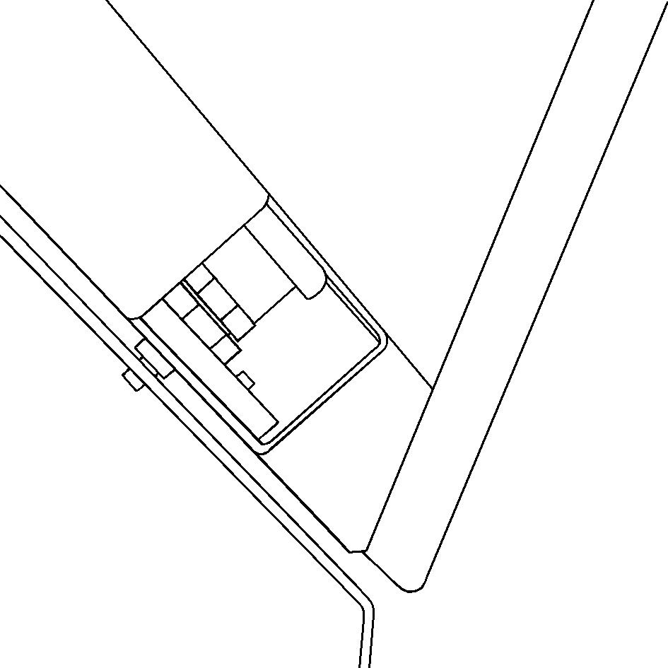
Transport and parking lock for upper conveyor
In order to prevent the upper conveyor from accidentally swivelling during transport on the trailer or when parking for long periods, the groove of the lock (1) should be inserted in the associated support of the upper conveyor bracket for this purpose.
Only apply the lock when parking and for transport purposes during which the upper conveyor is rigidly placed on the trailer or has to be held. In other words, when the unit is not subject to swivel movements.
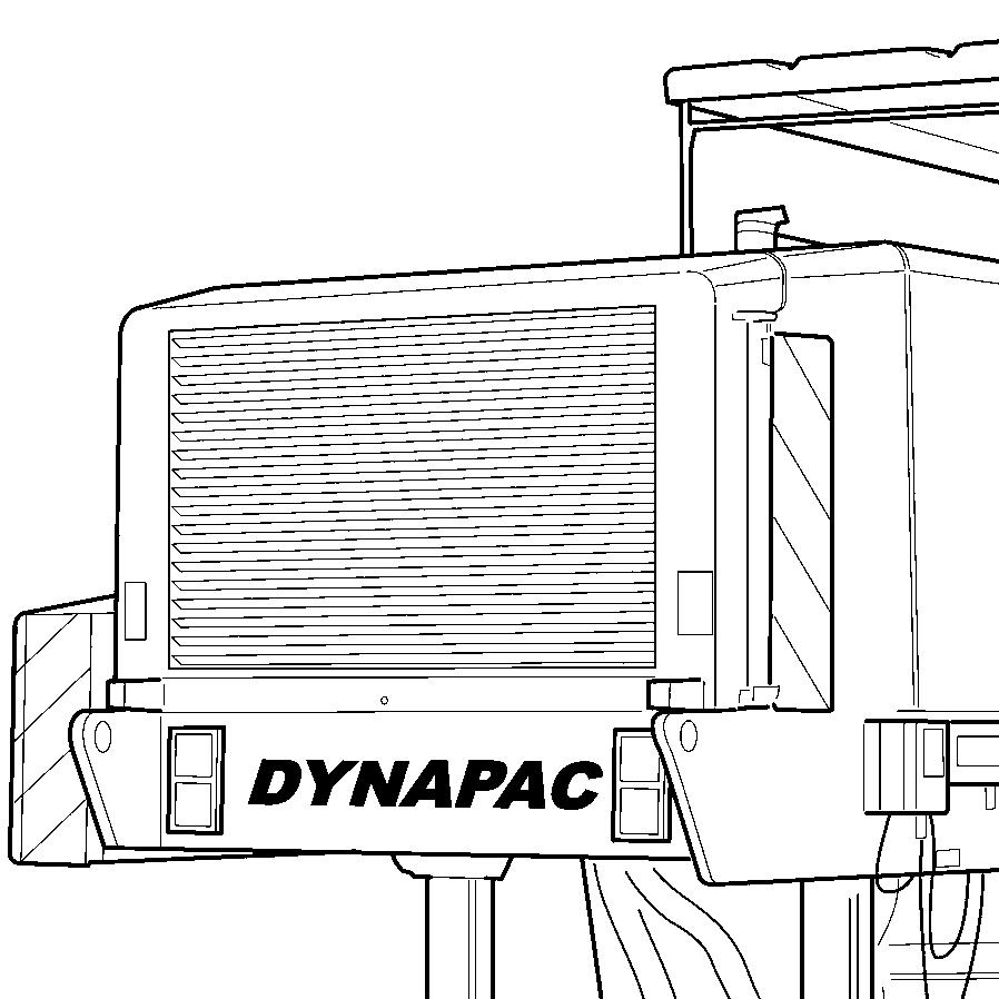
Wasser_LS2.wmf
Never apply the lock for transport purposes in which the upper conveyor is flexibly mounted, e.g. placed on a support fixture on the tractor machine of the trailer!
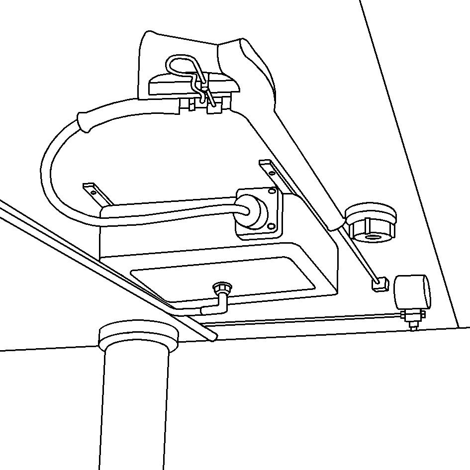
Monitoring camera ( )
Four video cameras are fitted to the machine to observe the area of the milling lane in front of the front drive unit, the area of the sliding shoe in front of the milling drum housing, the area of the moldboard behind the milling drum housing and the area of the rear track during reverse. If necessary, the cameras can be swivelled and individually set up.
-To swivel around axis (A), swivel the camera in the bracket up or down.
-To swivel around axis (B), unfasten the screws (1), swivel camera bracket and camera into the position required and retighten screws (1) correctly.
Tank system ( )
To store diesel, e.g. from a barrel.
-Filler hose with stop cock (1), for filling at the tank neck.
-Intake hose (2)
-On/Off switch (3)
If the system is not being used, close the stop cock and seal the intake hose with a sealing plug.
Observe instructions for working with diesel!
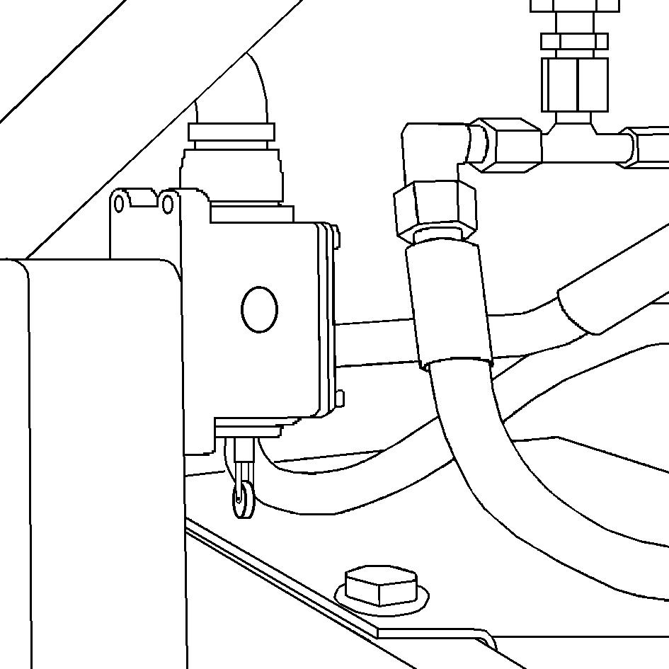
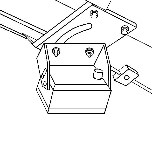
Compressed air system
The compressed air tank and connected maintenance unit can be found behind the storage room flap on the left-hand side of the machine.
There is a maintenance unit on the compressed air tank. This unit separates water from the air and enriches the airflow with a fine veil of oil and therefore ensures that the components connected have a longer service life.
-The air pressure required can be set on the pressure reducer (1).
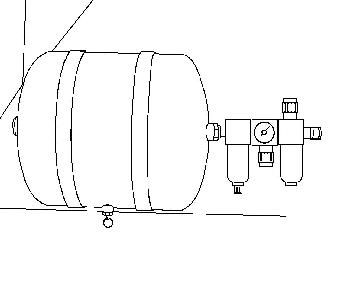
-The pressure level set is indicated on the pressure gauge (2).
-Various compressed air tools (e.g. the pneumatic hammer punch) can be connected to the clutch (3).
The compressed air coupling is accessible from outside and can be found on the rear of the storage area cabinet.
When using the compressed air tools, ensure that the oiler (4) is filled with oil under pressure.
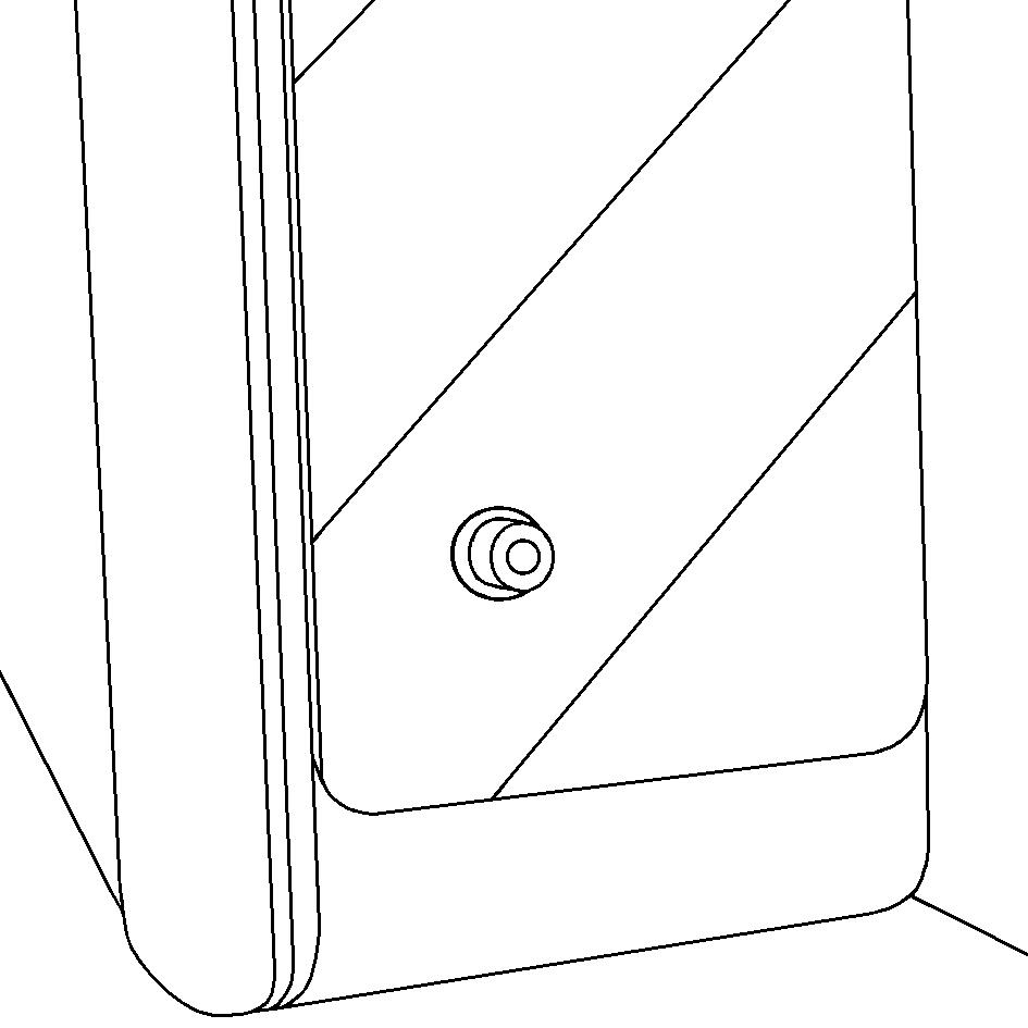
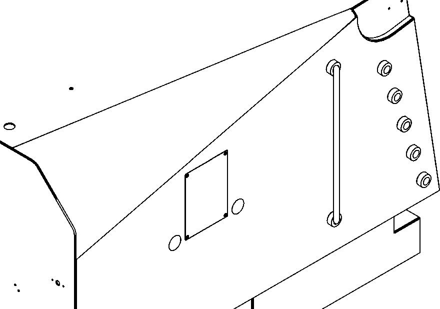
Storage area and protective flaps
The section of the storage area and protective flap which covers the operating side panels and the Levelling equipment (1) can be folded for operations.
-Pull detent (2) and now move the foldable section inwards.
-Press the two flap sections together so that both bracket sections are pressed into one another.
To close the flap, proceed in reverse order.
Risk of crushing! Ensure that no one reaches into the joint areas during the folding process as there is a risk that fingers and hands will be crushed.
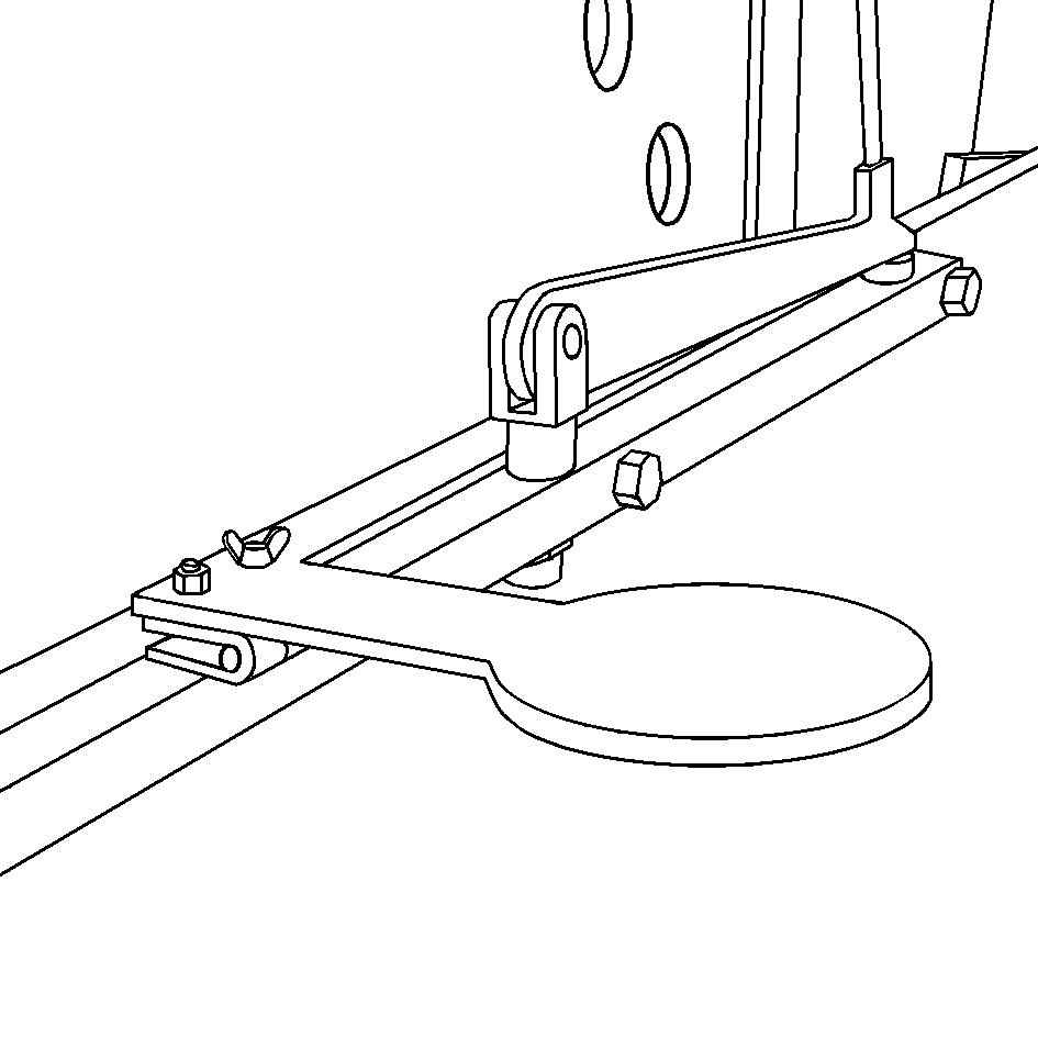
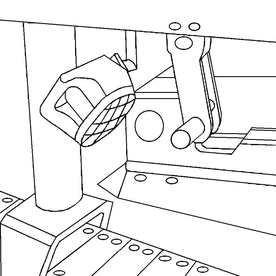
Lane pointer
A detachable lane pointer can be mounted on both front drive units.
The lane pointer can be used to work along one particular longitudinal mark which is at a specified distance from the machine.
The machine should then be controlled ensuring that the suspended plumbline (1) is above the mark.
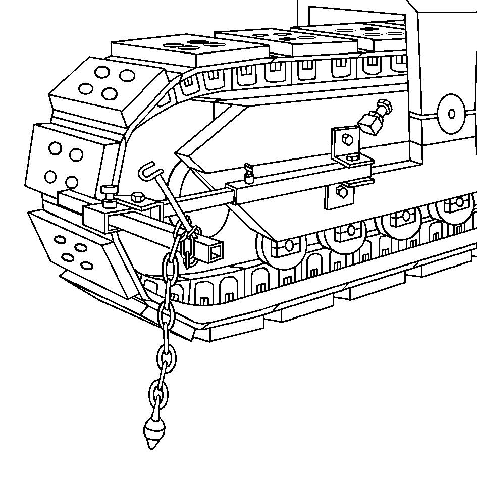
-To set the distance to the mark, unfasten wing screw (2), move the pipe into the position required and retighten the wing screw correctly.
-To remove the lane pointer, unfasten wing screw (3) and pull the fixture out of the bracket.
-If the lane pointer is not used for some time, the chain can be used to hang the plumbline in the bracket (4).
Hinged warning sign
The hinged warning sign is located on the rear of the machine, on the right.
The sign should be swivelled out if this side of the machine is on the offside, closest to passing traffic or if the machine is driven on public highways.
-Slightly raise the warning sign so that the detent pin no longer reaches into the bore.
-Swivel the sign through 90° and lower into the detent bore.
To transport the machine, fold in the warning sign. Danger of accidents, very wide vehicle.
Tool holder
A console (1) is fitted on each of the inner sides of the rear traction units. These can be used to store bit boxes or toolboxes.
During operation, the parts needed can be safely transported in this location. During maintenance work, these areas provide better access to tools.