5 minute read
6.1Liquid crystal display (1)

from Dynapac Cold Planer PL 2000 S PL 2000 LS Operating Instructions Manual 900981225 - PDF DOWNLOAD

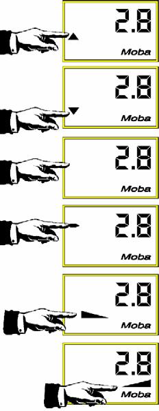
The display symbols have the following meanings:
SymbolMeaning
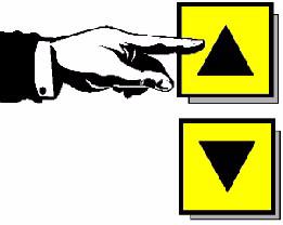
ARROWS
RAISE (12) / LOWER (13) Controlled controller output
Value without prefix (14) Positive display value
Value with negative prefix (15) Negative display value
Bar dropping to the right (16) Slope to the right
Bar dropping to the left (17) Slope to the left
Activation message
A display test is conducted once the digital controller has been activated. During this test, all segments of the LC display and all function lamps are activated for approx. 2 seconds. Should symbols not appear on the display, please contact After-Sales Service.
Sensor message
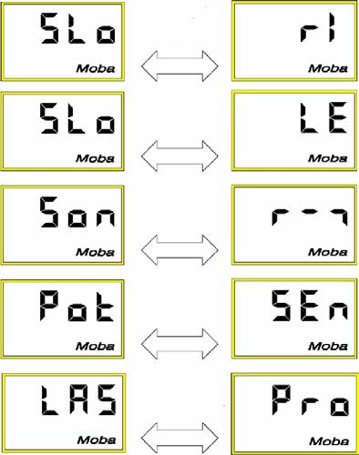
After the activation message, the digital controller briefly twice indicates the sensor connected using an alternating display image. While this image is displayed, the two direction lamps also flash. The control then automatically changes into operating mode.
If the sensor has been changed, the controller continues to issue the alternating sensor message until this message is acknowledged (by pressing any button). This should remind the user that the sensor has been changed and that the settings for the sensor are being checked accordingly.
LED display
The LED‘s are only used to provide the operator with a better display of the status of each of the activated valve outputs. Its display is simply an enlarged and detailed depiction of the function of the arrow symbols on the LC display. The LED display is particularly useful when the operator is at a great distance from the controller and if the sun is strong.
LC displayLED displayStatusFunction
Arrow lit contin. Arrow lit contin.
Large control variance
RAISE control output constantly lit
Arrow flashing Arrow flashing
Average control variance
RAISE control output runs through cycle with large pulse width
Arrow flashing Bar lit/arrow flashing
Small control variance
RAISE control output runs through cycle with small pulse width
No active arrows Bar lit
No control variance
Control outputs not activated
Arrow flashing Bar lit/arrow flashing
Small control variance
LOWER control output Lower runs through cycle with small pulse width
Arrow flashing Arrow flashing
Average control variance
LOWER control output runs through cycle with large pulse width
Arrow lit contin. Arrow lit contin.
Large control variance
LOWER control output constantly lit
ItemDesignationBrief description
1 Liquid crystal display left side
2Not in use
3 Slope / height display changeover left side
4Receptacle
5 Liquid crystal display right side
6Not in use
Actual value display for left-hand side of machine. Display is easy to read, even in poor light, thanks to integrated lighting.
When this key is pressed, the display changes from the actual height value on this side of the machine to the machine’s slope value or vice versa.
For connecting with the associated connection cable on one of the operating panel’s receptacles and/or for connecting with the MOBA-matic.
Actual value display for right-hand side of machine. Display is easy to read, even in poor light, thanks to integrated lighting.
7 Slope / height display changeover right side refer to item (3)
8Receptaclerefer to item (4)
9 cm/inch changeover
When this key is pressed, both displays change from cm to inch or vice versa.
Connection:
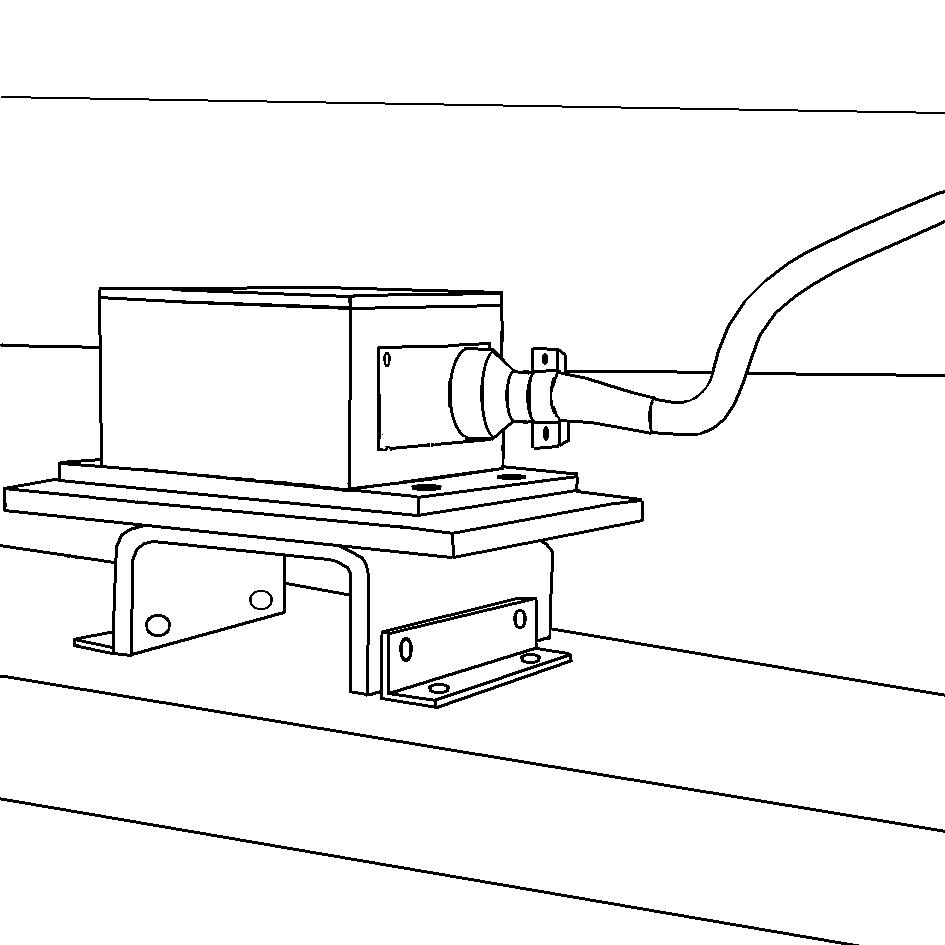
Both digital controllers and the actual value display, on the back of which there is a knob, are pushed from above into the brackets which are located right next to the lower controls on the rear machine section and/or on the rear side of the machine frame.
If equipped appropriately, you have the option of fitting both controllers next to one another on one side of the machine or on the rear of the machine.
If previously removed, the plug connections should then be established.
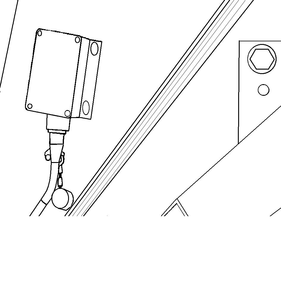
-The two connection boxes (1) are located very close to the controller on the underside of the machine frame. The connection to the controller is established via two sockets.
-The cable sensor for the side board of the left-hand side of the machine (2) can be found behind the flap of the powered belt housing.
-The cable sensor for the side board of the right-hand side of the machine (3) can be found directly on the machine frame above the shield.
-The transverse slope sensor (4) is housed in the centre of the rear section of the milling drum housing. The left-hand socket (viewed in direction of travel) is provided for the connection. The connections of the right-hand side remain unassigned.
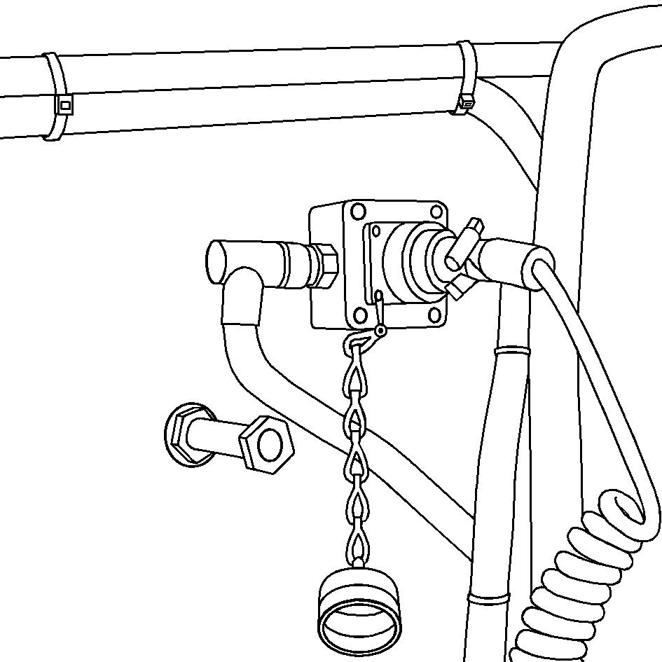
Proceed as follows during the connection process:
-Unscrew protective cap from connector
-Fit connector in position determined by plastic ridge on receptor, and groove in side of connector.
-Firmly screw on cap ring to secure the connector.
Equipping with other sensors / conversion
For the option of equipping the machine with other or additional sensors, the devices shown can be connected to the individual connection points on the machine. The connection points are located on the machine frame to the left and right
-At front: inside machine frame
-At centre: outside machine frame
-At rear: underside of machine frame
If working with optional ultrasound height sensing on the side board, the associated equipment must be set up.
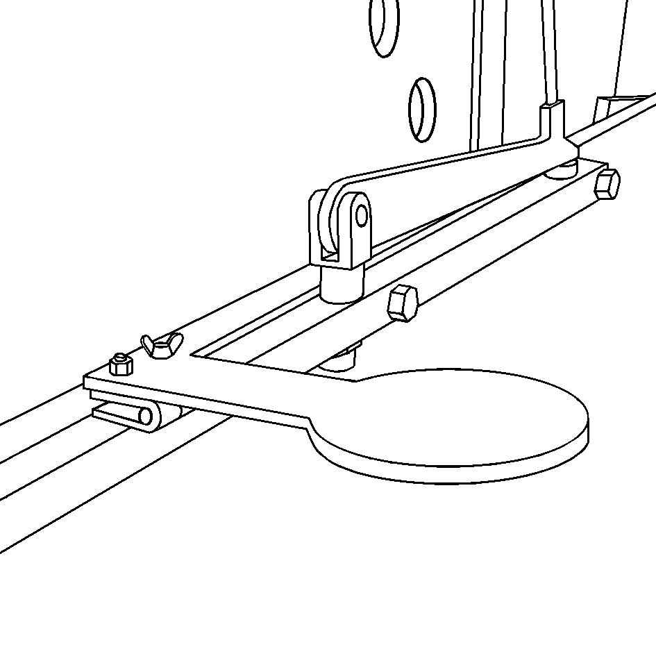
-Swivel out the sensor brackets (1) from both sides of the machine.
-Fold up the two reflectors (2).
-Fit the ultrasonic sensors (3) in the retaining fixtures.
-Establish plug connection (4), secure with cap.
Do not undertake connections when the machine is operating or the machine elements are being driven!
Always check that the connector / connection cable is not damaged! Keep the thread of the plug connections and the cable connections free of dirt and grease to avoid poor contacts. Only appropriate cleaning agents should be used for cleaning purposes.
The control system for protecting against theft and damage can be taken off and should be removed from the machine at the end of work every day and kept in a safe place.
Button usage and possible button combinations on the digital controller during milling
UP/DOWN buttons
These buttons are used to change the nominal value in automatic and manual mode, i.e. the machine responds to the press of a button and depending on the sensor connected, either changes its milling depth or slope. The newly set nominal value does not need to be confirmed using the SET button in these operating modes.
In semi-automatic mode, the nominal value is specified, i.e. the machine will not yet respond and only responds in automatic mode once the machine has been shifted back into automatic mode.
In semi-automatic or automatic mode, the nominal value is changed as follows
-height sensors: continuously in 1/10 stages, in cm, inches of feet depending on setting selected
-transverse slope sensors: in 1/10%, 5/100% or 2/100% depending on transverse slope resolution selected
UP/DOWN buttons (pressed at same time)
During the milling process with the height sensors in automatic mode. The nominal value is immediately set to 0 (useful when milling recesses)
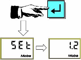
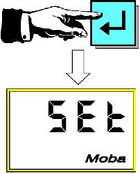
SET button
-When using the Digi-Slope sensor, the SET button must always be used to confirm an actual slope value set in manual mode or preselected or existing in semi-automatic mode. This must be done before changing over into automatic mode so that this value is adopted as the nominal value.
-If when using the height sensors, the actual value or a pre-selected value is to be adopted as the nominal value following changeover into automatic mode, the SET button should only be briefly pressed, otherwise calibration to zero is conducted (refer to zero setting)
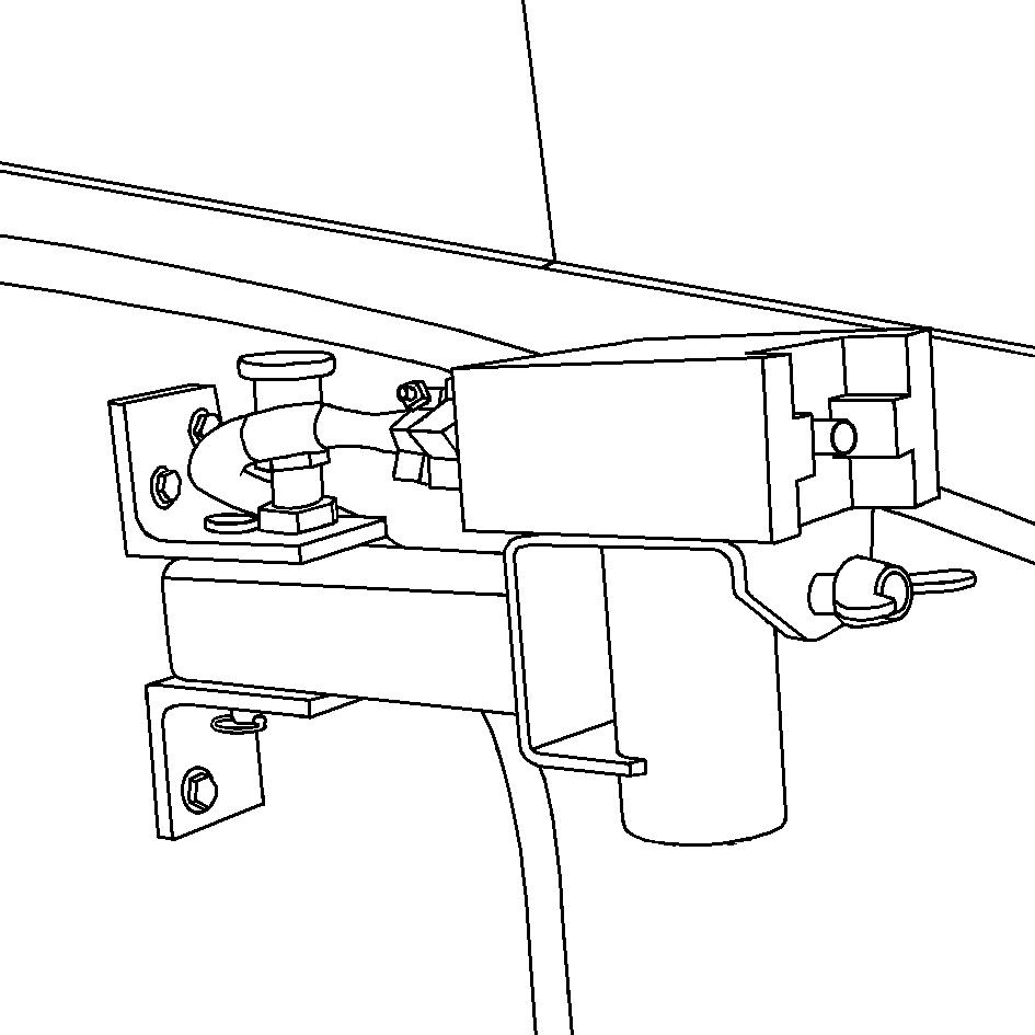
Switch for levelling function and EMERGENCY STOP button on rear lower control panel
Unwanted processes which arise when setting the milling values, such as the front chassis legs moving in and out in an uncontrolled manner, can be stopped at any time by moving the levelling function switch (1) from „AUTO“ to „0“ or by pressing the EMERGENCY STOP button (2).
6.3Basic settings
Always conduct all basic settings in manual mode!
(Function lamp off)
The levelling equipment cannot activate automatic mode via the digital controller.
During milling, the automatic mode setting can only be conducted from the main operating panel of the upper operator’s control station. During the milling process, changes to all operating modes (automatic, semiautomatic, manual) can only be conducted on the controller via the A/M button once automatic mode has been activated.
During the milling process, there is also the option of choosing between automatic mode („AUTO“ position) and semiautomatic mode („0“ position) using the rear side operating panel.