6 minute read
4Controls

from Dynapac Cold Planer PL 2000 S PL 2000 LS Operating Instructions Manual 900981225 - PDF DOWNLOAD

4.1Controls at operator’s control station
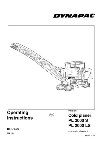
Driver’s seat on left / right
A driver’s seat can be found on both the left and right. The seat should be set to the driver’s requirements before work is started.
-To set the correct seat hardness, fold the crank on the handwheel (1) forwards and rotate until the approximate weight of the driver appears on the display (2).
-To set the correct distance from the operating panel, pull lever (3) upwards and slide the seat forwards or backwards as required.
-Pull up the grip recess (4) on the back of the seat and set the height of the backrest.
-Should the driver’s seat have to be moved beyond the outer edge of the machine, the locking lever (5) must be applied and the complete seat bracket moved in the corresponding direction. Then move the lever back to lock. The armrests ( ) can also be swivelled upwards.
Risk of accident! If possible, always select the operator's control station on the nearside, i.e. furthest away from oncoming traffic.
Always ensure that the operating panel and driver's seat are correctly locked into place.
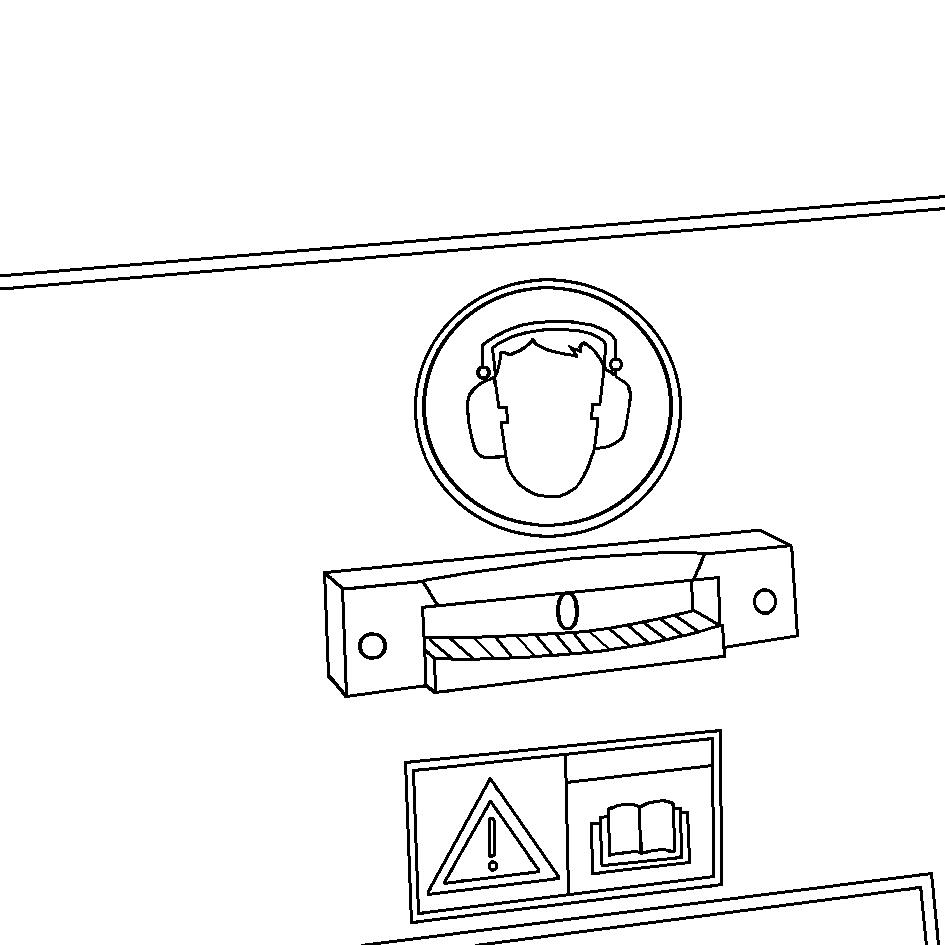
Battery’s main switch
The battery’s main switch can be found under the right-hand bottom lid. It separates the power supply from the battery for the main fuse.
The safeguard of the bottom lid can be opened using a square wrench.
-To deactivate the master switch, turn to the left and remove.
-Cover aperture with protective cap (2).
Do not lose the removed master switch because otherwise you will not be able to start the machine.
For the specifications governing all fuses, refer to Chapter „Maintenance“.
Batteries
Behind the maintenance flap, one battery of the 24 volt system can be found on both the left and right behind the driver’s seat.
For the specifications, refer to Chapter B „Technical data“. For maintenance, refer to Chapter „Maintenance“.
Only undertake external starting in accordance with the instructions (refer to Section „Starting machine, external starting (starting aid)“.
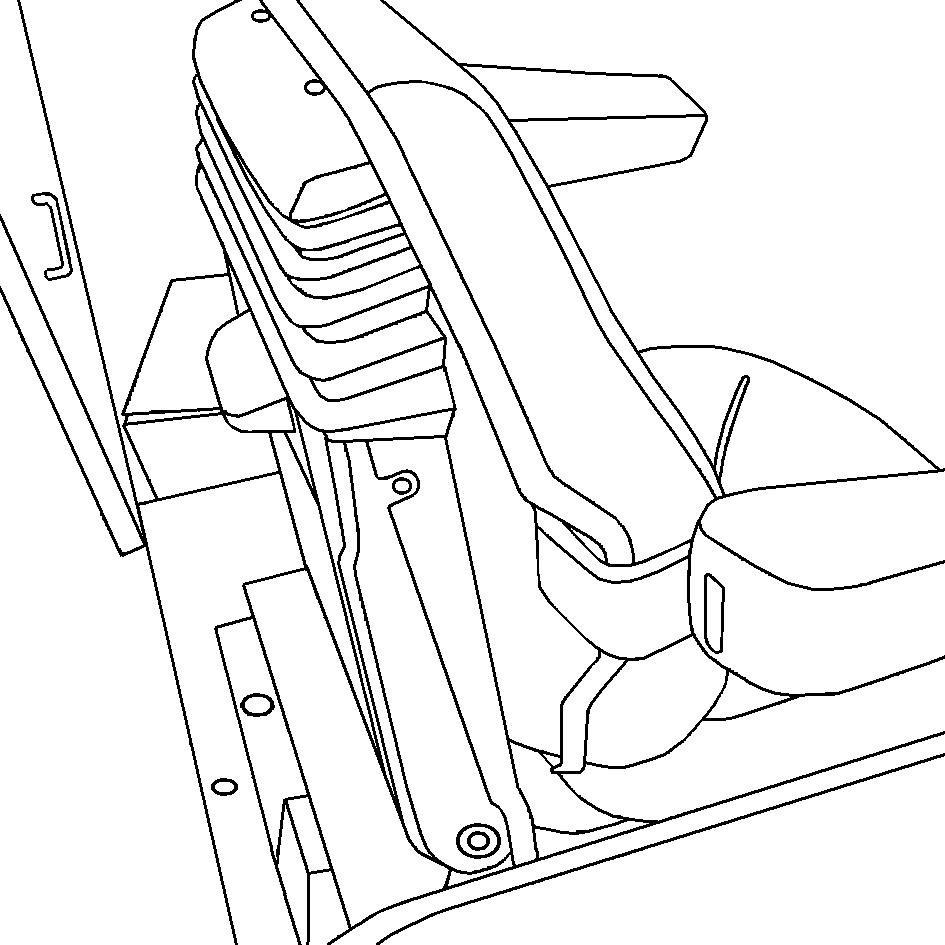
Tilt display
A tilt display (1) can be found in the centre of the front panel in the operator’s control station.
The tilt display is used to provide a visual estimate of the size of the machine’s present tilt.
-The indicator ball in the sight glass shows the machine tilt on the scale fitted below the sight glass.
A warning message is displayed on the operating panel once the tilt exceeds 10% (O 13 %).
In certain situations, when the machine tilt exceeds 10%, there is a risk of tipping! Risk of accident!
Fuel tank gauge
The fuel tank is equipped with a gauge:
-Sight glasses (1)
Check fuel level several times a day on this gauge.
Folding ladder
A robust ladder with slip-free steps can be found on both the left and right. The ladder can be folded up on both sides of the machine.
-By gripping a rung or the slip-free step, push the ladder upwards – the ladder will fold in as moving up.
-To fold out, pull the ladder down – the ladder will fold out as moving down.
The lower segment (1) of the ladder can be taken off for safekeeping.
-Use a square wrench to open lock (2) under third rung.
-Pull out the lower segment (1) and attach in holes of upper segment (3).
-Close lock (2) and secure the segment attached in this way in this position.
Risk of crushing! Do not reach into the joint area during the folding process as there is a risk that fingers and hands will be crushed.
Never climb up/down ladders on the machine during travel. Hold tight when climbing up and down ladders.
Guardrail
There is one guardrail on both the left and right between the ladders and operator’s control stations. The guardrails must be set up as required and once the operator’s control station has been entered.
Each of the guardrails consists of two outer sections (1) and two inner sections (2).
-To adjust the guardrail, raise the outer section (1) and after swivelling into the retaining bracket through 90°, lower it back, pointing in the right direction.
The diagrams shown here indicate the different situations in which the guardrails should be set up. (Diagrams show left-hand side of the machine, viewed from outside.)
-(A) Open guardrail - to enter and exit the operator's control station
-(B) Guardrails externally locked (driver's seat and operating panel set up in normal position)
-(C) Guardrails externally and internally locked (driver's seat and operating panel moved beyond the outer edge of the vehicle.)
-(D) Guardrails (externally and internally) locked at rear, front outer section locked (driver's seat moved beyond the outer edge of the vehicle, operating panel set up in normal position.)
-(E) Guardrails (externally and internally) locked out front, front outer section locked (driver's seat set up in normal position, operating panel moved beyond the outer edge of the vehicle.)
Risk of crushing! Do not reach into the joint area during the folding process as there is a risk that fingers and hands will be crushed.
Transport position for ladder and guardrails
To reduce the machine width for transport and as an additional safety measure when parking in public places.
-Fold up the ladder on both sides of the machine and swivel the guardrails in front of the slip-free step.
Hydraulic folding roof operations
The hydraulically folded roof is locked to the front suspension of the left and righthand side of the machine by a retaining bracket (1). The key-operated switch (4) for actuating the folding roof and hood hydraulics can be found to the left of the belt drive’s protective box.
The roof can be raised and lowered without the drive engine having to be started.
-Slide down the spring-loaded detent pins (2) on both sides of the machine. -Check that the changeover valve (3) (under the compensation tank behind the maintenance flap) is in position (A).
-To lower the roof, turn the key-operated switch (4) to the left until the roof has lowered to its minimum level.
Risk of crushing! Ensure that no one reaches into the joint areas or the areas into which the roof is to be lowered during the folding process as there is a risk that fingers and hands will be crushed.
-To raise the roof again, turn the keyoperated switch (4) to the right until the roof has raised to its maximum height.
-Allow detent pins (2) on both sides of the machine to engage.
Hydraulic hood operations
The machine’s engine hood (1) can be opened and closed hydraulically and provides good access to the various monitoring and maintenance points. The key-operated switch (4) for actuating the folding roof and hood hydraulics can be found to the left of the belt drive’s protective box.
The hood can be raised and lowered without the drive engine having to be started.
-Check that the changeover valve (3) (under the compensation tank behind the maintenance flap) is in position (B).
-Turn key-operated switch (2) to the left until the hood is opened to its maximum level.
-To lock in this open position, slide the slotted detent sleeves (4) on both sides over the joint.
Risk of crushing! Ensure that no one reaches into the joint areas or the areas into which the roof is to be lowered during the folding process as there is a risk that fingers and hands will be crushed.
-In order to close the hood again, the two detent sleeves (4) have to first be slid away from the joints.
-Turn key-operated switch (2) to the right until the hood is fully closed.
Throttle valves for deployment speed of hood and roof
The hydraulic unit for hood and roof operation can be found behind the maintenance flap of the operator’s control station.
The unit has two throttle valves for setting the speed for raising and lowering the roof.
-Upper throttle valve (1): Turn adjustment button clockwise = slower speed for raising roof. Turn adjustment button anticlockwise = faster speed for raising roof.
-Lower throttle valve (2): Turn adjustment button clockwise = slower speed for lowering roof Turn adjustment button anticlockwise = faster speed for lowering roof.
Manual pump, hood and roof
A manual pump is fitted on the hydraulic unit should the roof or hood have to be raised when the battery is flat.
-On both sides of the unit: Once the lock nut has been loosened, screw threading dowel (3) in as far as possible and secure with lock nut.
-Press the pump lever (4) until the roof or hood is open.
Observe the information provided in the hood and roof operating instructions!
The threading dowel (3) must be unscrewed again for regular operations and locked using the lock nut.