6 minute read
4Normal on-road travel

from Dynapac Cold Planer PL 2000 S PL 2000 LS Operating Instructions Manual 900981225 - PDF DOWNLOAD

The machine is not intended for normal on-road travel and is not equipped for such circumstances. It should be used within enclosed building sites.
If the machine’s loading or unloading area is outside an enclosed building site or if the machine has to propel itself from one section of the roadworks to another, the machine must be dual-manned for safety reasons. All safety measures (cordoning off) required for this should be implemented.
If a machine has to be parked on a public highway, it should be cordoned off in accordance with the relevant regulations and secured to prevent the machine from rolling away, tilting or swivelling.
If machine components protrude into another lane of traffic during milling or manoeuvring, this should be briefly cordoned off until the hazard has passed.
The rotary beacons and hazard flasher are permanently activated during milling and transport, the warning signs on the machine are permanently folded down.
If necessary, the machine should always be used on the nearside, away from oncoming traffic.
For relocation or during journeys required over a long-distance (distances > 1 km), the machine should be transported on its transporter for technical and safety reasons.
5Articulation procedure of foldable upper conveyor (O)
5.1Folding in upper conveyor
The transport length of the machine can be significantly reduced using the foldable upper conveyor (available as an option).
Various operations are required and conditions should be checked and/or set to enable the upper conveyor to be folded in.
-The machine is on level ground and in a secure horizontal position.
-The upper conveyor is in its operating position.
-Milling drum is not activated.
-Loading and upper conveyors are not being operated.
Operations required:
-Lower upper conveyor until the front section of the belt frame touches the ground. If necessary, the front of the machine will have to be lowered via the chassis legs.
-Remove the interlock bolts (1) from both sides of the articulation range of the upper conveyor.
Keep the bolts somewhere safe so that they are not lost.
-If necessary, slowly raise the upper conveyor by extending the chassis legs and unfolding over the belt frame until the reversal interlock is reached.
-Open the left-hand reversal interlock (2) on both sides in the articulation range of the upper conveyor.
-Insert an appropriate aid into the support of the interlock hook and open interlock by turning lever to the right.
-Move the machine forwards slightly until the roll bar on the upper front section of the belt frame has sufficient contact with the ground. If necessary, the front of the machine will have to be raised via the chassis legs.
-Slowly raise the upper conveyor further until the front section of the belt frame lies on the rear section. The frame components are completely folded down.
-Insert retaining tab (3) on both sides of the belt frame.
-Remove retaining cotter pin, guide tab over the journal of the lower frame section and secure with cotter pin.
5.2Unfolding the upper conveyor
The procedure for unfolding the upper conveyor is exactly the same as the procedure for folding it in, but in reverse order.
Before the upper conveyor can be unfolded, the transport safeguards on both sides of the machine must be opened.
-Open retaining tab (3) on both sides of the belt frame:
-Remove retaining cotter pin, guide tab over the journal of the upper frame section and secure using the cotter pin.
-Open engaged interlock (4):
-Insert appropriate aid in to the support of the interlock hook and open interlock by turning lever to the left.
-The upper conveyor can be unfolded up to the point at which the reversal interlock is reached.
-Open the right-hand side reversal interlock (5) on both sides in the articulation range of the upper conveyor.
-Insert appropriate aid in to the support of the interlock hook and open interlock by turning lever to the left.
-Lower upper conveyor until the joint is fully unfolded again. If necessary, the front of the machine will have to be lowered via the chassis legs.
PL2000anew.cdr
Gelenk1.cdr
6Hydraulically foldable upper conveyor (O)
6.1Folding in upper conveyor
The machine’s transport length can be significantly reduced in a few simple steps by using the hydraulically foldable upper conveyor (available as an option).
To fold the upper conveyor, various preconditions must be checked and/or satisfied.
-Machine has been moved out of its milling lane and is therefore on as level a base as possible.
-The upper conveyor is in its operating position.
-Milling drum is not activated.
-Loading and upper conveyors are not being operated.
PL2000hydconv2.wmf/Steerunit3.wmf/Pl2000hydconv4.wmf
Steps required for folding process:
-Raise loading conveyor into its highest position.
-Firstly raise machine as far forward as possible over chassis legs then lower as far as possible to the rear.
-Connect control box (1) (in accessories) to socket (2) on left-hand side of upper conveyor.
-Press switch (3) on control box.
When this switch is pressed, a warning sounds and the upper conveyor starts to fold. The switch must be held down during the entire folding process.
Ensure that there is no one in the machine’s danger area!
-Once the upper conveyor is folded in completely, the upper section must be secured in this position using retaining tabs (4) and the corresponding articulated cotter pins (4a) located on both sides of the lower section of the upper conveyor.
-Remove control box (1) from socket (2) and use appropriate cover to close box.
6.2Folding out upper conveyor
To fold out, proceed as for the folding in process but in reverse. The following should be noted:
-Fold the upper conveyor back in to the stop by pressing switch (3) on control box (1).
-Remove retaining cotter pin (4a) from both sides of the upper conveyor and fold retaining tab (4) up over the bolts and again secure using the cotter pin.
-Fold upper conveyor all the way up by pressing switch (3).
When pushbutton is pressed, a warning sound can be heard and the upper conveyor begins to fold. The pushbutton must be held down during the entire folding process.
Ensure that there is no one in the machine’s danger area!
The folding process is complete once the belt is correctly retensioned (visual inspection).
Steerunit3.wmf/PL2000hydconv5.cdr/
Pl2000hydconvlatch2.cdr/clamp.tif
7Loading by crane
In the event of breakdown, should it no longer be possible for the machine to be towed or if it cannot be loaded in any other way, there is also the possibility of raising it by crane.
Use lifting tackle with sufficient load bearing capacity. (For weights and dimensions, refer to Chapter B). Ensure that the steel cables, shackles and crosshead are large enough.
Four attachment points (1,2) are provided on the machine frame for loading the vehicle using lifting gear.
-Secure vehicle wherever it is parked up.
-Move upper conveyor into operating position.
-Weather protecting sun roof may be deployed.
-Safely store loose components and accessories, such as removable spotlights or levelling equipment parts.
-Attach lifting gear to the four attachment points (1, 2).
During transport, ensure that the machine is always horizontal! Ensure that there is nobody in the danger area.
Risk of accident! When loading by crane, the swivel hydraulics of the upper conveyor must always be moved into their operating position (1) because otherwise the machine may e.g. swivel outwards accidentally if on a slight incline.
8Towing procedure
Observe all regulations and undertake all necessary cautionary measures which apply to the towing of heavy construction machinery.
The tractor vehicle must be such that it can still hold the machine when travelling downhill. Only use authorised towbars!
Only disengage travel drive and only release traction unit brakes once the machine is sufficiently secured to prevent it from accidentally rolling away or once it has already been correctly connected to the towing vehicle.
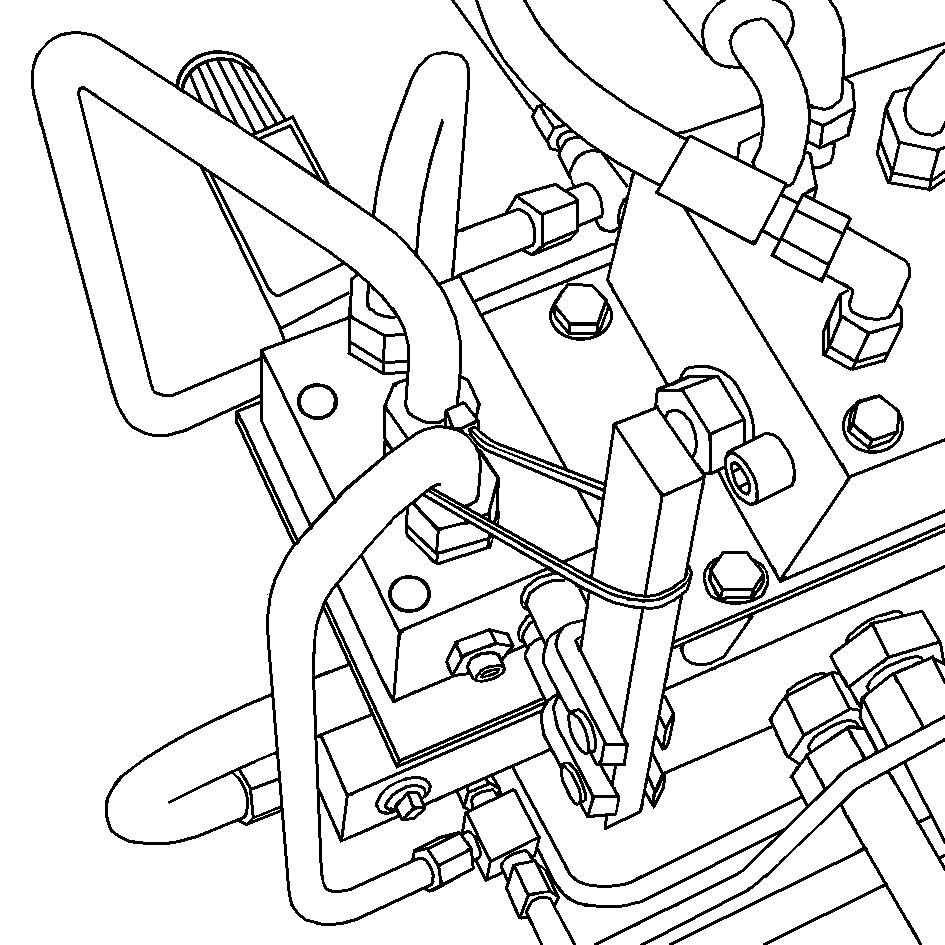
A valve and manual pump are located under the right bottom plate of the operator’s control station. These must be actuated if the machine is to be towed.
-In order to disengage the hydraulic circuit for towing, the valve (1) under the manual pump must first be changed over.
-Then the lock nut (2) on the manual pump must be released and the threading dowel (3) screwed as far as possible into the pump. Re-tighten the lock nut for safety.
-Now the lever of the manual pump (4) must be pressed until sufficient pressure has built up and the traction unit brakes have released themselves.
The brakes will release themselves at a pressure of approx. 30 bar.
The machine can now be carefully and slowly towed out of the construction site area. Always tow the shortest possible distance to transport equipment or to the nearest safe parking area.
Once towing is complete, change back the valve (1), unscrew the threading dowel (3) again (several turns) and use the lock nut (2) to secure. The traction unit brakes are now active again and the machine is secured to prevent it from rolling away.
9Secure before parking up
When parking on publicly accessible areas, the machine should be secured to ensure that unauthorised persons and children cannot cause any damage to it. The machine should be parked on level ground, the upper conveyor lowered and, if possible, swivelled into a safe area.
-Lower scraper, sliding shoe and side boards.
-Remove ignition key (1) and master switch (2) and take them with you – do not leave them „hidden“ in the machine.
-Close all operating panels (3) and side operating units (4) along with the associated protective covers.
-Fold up the ladder on both sides of the machine and swivel the guardrails in front of the slip-free step (5).
-Safely store loose components and accessories such as removable spotlights or levelling equipment parts.
-Deploy folding roof, remove key.
-Lock all bottom lids, hoods and storage rooms.
-Fold out full length of service supports so that the vehicle cannot be lowered should attempts be made to do so.