37R116 Axle Service Manual
Ring Gear Installation
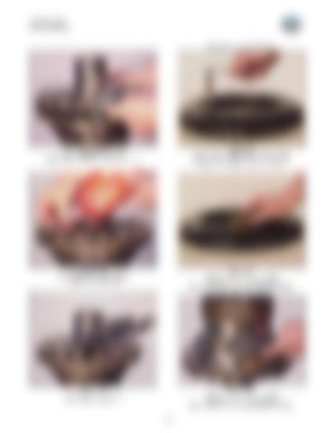
Figure 127 Install differential flange half. NOTE: Align identification marks as shown.
Figure 130 Clean foreign material and/or cured thread locking compound from holes with M16x2 tap. Remove remaining residue from holes.
Figure 128 Apply Loctite 262 or equivalent to (2) cap screws and install.
Figure 131 Use hone stone or file to remove nicks or burrs from mounting face. NOTE: Be sure to remove all abrasive residue.
Figure 129 Tighten (2) cap screws to 24-27 Nm [18-20 LBF/FT].
Figure 132 Use hone stone or file to remove nicks or burrs from mounting face. NOTE: Be sure to remove all abrasive residue.
52


