2 minute read
Pinion Installation and Adjustment
Figure 133 Heat ring gear to 93-100°C [200-212°F] and Install. Caution: Use gloves to avoid injury.
Figure 135 Heat and install differential bearing cone. Reference bearing heating and freezing guidelines on page 23. Figure 136 Locate ring gear mounting distance dimension located in this area and record.

Figure 134 Temporarily install (2) ring gear mounting screws 180° apart and tighten to 135 Nm [100 LBF/FT]. Allow assembly to cool before installing additional screws. IMPORTANT: Using a .05 mm [.002”] feeler gauge check several locations around ring gear to be sure there is no gap between the ring gear and differential body mounting faces. NOTE: Assembly is shown with ring gear down for clarity. This procedure should be performed with assembly in same position as shown in figure 133. Pinion Installation and Adjustment


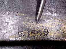
Figure 137 Number as it appears in figure 136.
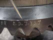
Figure 138 Locate ring gear mounting distance dimension on ring gear and record.

Figure 139 Measure height of pinion inner bearing cup and cone and record. Calculate ring and pinion mounting distance shim as follows:
Example
Number from housing 232.560 mm [9.1559”] Number from ring gear - 186.106 mm [7.3270”] Bearing height - 45.974 mm [1.8100”] - .127 mm [ .0050”] Shim thickness required .353 mm [ .0139”]
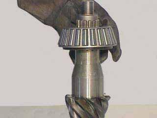
Figure 140 Heat and install pinion inner bearing cone. Reference bearing heating and freezing guidelines on page 24. Figure 141 Install pinion outer bearing cup.
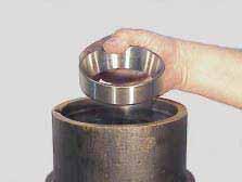

Figure 142 Install mounting distance shim as determined in figure 139.

Figure 143 Freeze and install pinion inner bearing cup. Reference bearing heating and freezing guidelines on page 24.
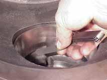
Figure 144 Check for proper seating of pinion inner and outer bearing cups. Reference bearing heating and freezing guidelines on page 23.

Figure 145 Lubricate pinion inner bearing cone.

Figure 146 Install pinion. Figure 147 Lubricate pinion outer bearing cone.
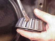

Figure 148 Heat and install pinion outer bearing cone.

Figure 149 Install flange.


