4 minute read
Wheel Bearing Preload Setting Procedure


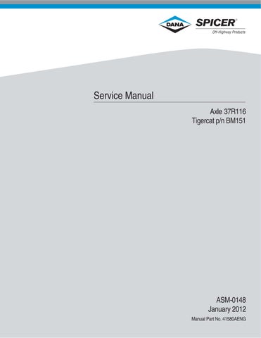
Figure 255 Install planet carrier. IMPORTANT: Position planet carrier on the axle shaft splines so the threaded holes in shaft are equally spaced between the planet gear bearing bosses as shown in figure 258. This will allow access to the socket head screws between the gears when removing or installing a complete planetary assembly.
Figure 256 Measure thickness of clamp plate and record. Figure 259 Shock axle shaft flange in several locations while rotating shaft.
Advertisement
Wheel Bearing Preload Setting Procedure

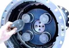
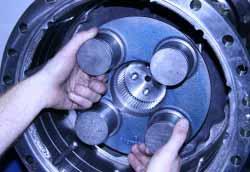
Figure 257 Install clamp plate. Figure 258 Install (4) socket head screws and tighten evenly to 33.9 Nm [25 LBF/FT].
Figure 260 Retighten screws to 33.9 Nm [25 LBF/FT]. Repeat shocking and torquing until screws no longer advance at 33.9 Nm [25 LBF/FT].
Initial Shim Pack Calculation
Remove (4) socket head screws and rotate clamp plate until holes in plate and shaft do not line up. Using depth gauge measure from top of clamp plate to end of axle shaft. Subtract thickness of clamp plate recorded in figure 256 from depth measurement for initial shim thickness.
EXAMPLE: Depth Measurement 21.2 mm [.83”] Clamp Plate Thickness 22.6 mm [.88”] Initial Shim Pack 1.4 mm [.050”]
Figure 261

Figure 262 Select an initial shim pack thickness from the calculation in figure 261. NOTE: The original shim pack or 1.4 mm [.50”] may also be used as a starting point.
Figure 263 Install clamp plate, (4) socket head screws and shim pack. Figure 266 Measure rolling torque. Adjust shim pack thickness as required by repeating steps in figures 262-266 to attain a rolling torque within 16-23 Nm [12-17 LBF/FT]. NOTE: Rolling torque must be returned to 0.0 before increasing shim pack thickness by shocking shaft after screws are loosened.

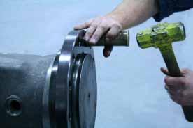
Figure 264 Tighten (4) socket head screws evenly to 286-316 Nm [211-233 LBF/FT] while rotating axle shaft.
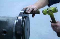
Figure 265 Rotate and shock shaft.


Figure 267 Remove (4) socket head screws, one at a time, apply Loctite 262 or equivalent and reinstall.
Figure 268 Tighten (4) socket head screws evenly to 286-316 Nm [211-233 LBF/FT] while rotating axle shaft.

Figure 269 Heat planet gear and bearing assembly. Reference bearing heating and freezing guidelines on page 23. Figure 270 IMPORTANT: Large radius on bearing inner race must be installed down or towards the planet carrier.


Figure 271 Install planet gear and bearing assembly.

Figure 272 Install planet gear and bearing snap ring.

Figure 273 Turn snap ring in groove to verify that it is fully seated in groove. Repeat steps in figures 269-273 for remaining (3) planet gears.

Figure 274 Install internal ring gear.

Figure 275 Align eye brows in ring gear with eye brows in trumpet arm. Figure 278 Position snap ring ends between eye brows as shown.
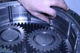
Figure 276 Install (12) dowel pins.

Figure 277 Install snap ring. NOTE: If axle has brakes, snap ring is not used in this position, proceed to figure 280.


Figure 279 Install sun gear. NOTE: This completes reassembly of trumpet arm on an axle without brakes. Repeat process for opposite trumpet arm.
Figure 280 Install brake abutment plate aligning eye brows in plate with dowel pins. NOTE: If brake pistons have not been positioned on the differential assembly the abutment plate is needed for that procedure. Reference figures 228-230 to align pistons. Figure 283 Coat both sides of brake friction plate with axle lubricant and install.


Figure 281 Install snap ring. Center snap ring ends between eye brows in housing. Reference figure 278. Figure 282 Apply heavy coat “glob” of grease to (4) brake piston return springs and install. Install sun gear.


Figure 284 Install brake reaction plate. Repeat process for opposite trumpet arm.