2 minute read
Hydraloc Seal Retainer Assembly and Installation
Figure 196 Install stub shaft. NOTE: The sun shaft and a socket can be used to perform this procedure.

Advertisement
Figure 197
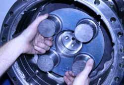
Step #1 Hold pinion and rotate side gear five turns in each direction. Differential clutch must turn freely with a maximum torque of 34 Nm [25 LBF/FT].
Step #2 Hold side gear and rotate pinion in both directions to make several passes through the gear contact checking compound on the ring gear. Figure 198 Inspect tooth contact pattern on ring gear. Compare to tooth bearing charts on pages 25 & 26 and make adjustments if necessary as indicated.
Figure 199 Apply continuous coat of Loctite 620 or equivalent to outside diameter of inner Hydraloc seal.
Figure 200 Using appropriate driver install inner Hydraloc seal. NOTE: Seal is installed with sealing lip down or towards center of seal retainer. Reference tool drawing on page 90.

Hydraloc Seal Retainer Assembly and Installation


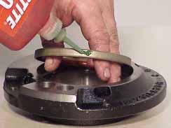
Figure 201 Apply continuous coat of Loctite 620 or equivalent to outside diameter of outer Hydraloc seal.
Figure 202 Using appropriate driver install outer Hydraloc seal. NOTE: Seal is installed with sealing lip down or towards center of seal retainer. Reference tool drawing on page 91.
Figure 203 Apply Loctite 262 or equivalent to seal retainer plug. Figure 204 Install seal retainer plug. NOTE: Plug end to be flush with mating surface.
Figure 205 Coat with grease, to hold in position, and install (2) seal rings in seal retainer.
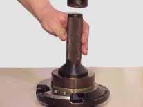

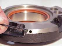
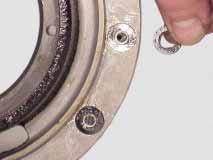

Figure 206 Insert seal retainer installation tool. Reference tool drawing on page 95.

Figure 207 Coat inner and outer Hydraloc seal lips with grease.
Figure 208 Carefully install seal retainer. Note: Holes on seal retainer must be aligned with holes on the pressure and tank ports on the differential retainer.

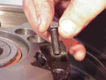
Figure 209 Install (4) seal retainer cap screws. Figure 210 Tighten seal retainer cap screws to 24-27 Nm [18-20 LBF/FT].


Figure 211 Apply Loctite 262 or equivalent to differential adjusting nut lock socket head screw. Install socket head screw in one of the two holes that allow it to clear the lugs on the adjusting nut.
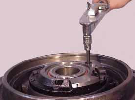
Figure 212 Tighten adjusting nut socket head lock screw to 48-50 Nm [35-37 LBF/FT].


