1 minute read
Backlash and Contact Pattern Setup and Adjustment
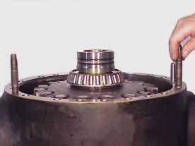
Figure 186 Lubricate differential bearing cone with axle lubricant.
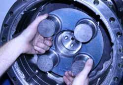
Figure 187 Install (2) piston rings. Coat rings with grease and center in grooves.
Advertisement
Figure 188 Install (2) alignment pins located 180° apart. Figure 189 Install differential retainer.


Figure 190 Install (4) retainer cap screws and tighten to 24-27 Nm [18-20 LBF/FT].
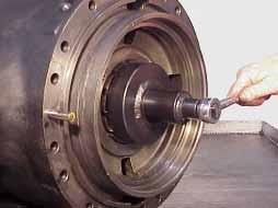
Figure 191 Tighten differential adjusting nuts to a minimum of 41 Nm [30 LBF/FT]. Rotate pinion back and forth while performing this step to assure that detectable backlash exists and ring gear is not being forced into pinion gear. Reference tool drawing on page 92.
Backlash and Contact Pattern Setup and Adjustment


Figure 192 Set up magnetic base dial indicator as shown to measure ring and pinion back lash.
With ring gear being held stationary, rock the pinion flange back and forth gently while watching the reading on dial indicator. Backlash specifications are as follows: 37R 4.556 ratio with 6C-TP Flange .46-.74 mm [.018-.029”] 37R 4.556 ratio with 7C-TP Flange .48-.79 mm [.019-.031”] 37R 5.125 ratio with 6C-TP Flange .56-.89 mm [.022-.035”] 37R 5.125 ratio with 7C-TP Flange .58-.94 mm [.023-.037”]
If the readings are out of specification, move the differential adjusting nuts inward or outward together. IMPORTANT: Recheck differential bearing preload after the proper backlash reading is achieved. Refer to figure 191.
Figure 193

Figure 194 Install differential adjusting nut lock. IMPORTANT:Advance adjusting nut if necessary to line up mounting holes. Do Not loosen/back off nut. Figure 195 Apply Loctite 262 or equivalent to (2) nut lock cap screws and install. Tighten to 24-27 Nm [18-20 LBF/FT].


