1 minute read
Pinion Seal Installation


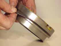
Figure 150 Install pinion spacer.

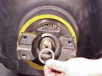
Figure 151 Install pinion nut and tighten to 1261-1396 Nm [930-1030 LBF/FT].
Figure 152 Check pinion bearing rolling resistance and record. Pinion rolling resistance recorded in figure 152 should be 1.13-3.95 Nm [10-35 LBF/IN].
If within specification remove nut, spacer and flange.
If not within specification repeat steps in figures 150-152 making appropriate spacer substitution.
If rolling resistance is too low reduce spacer thickness. If rolling resistance is too high increase spacer thickness.
Figure 153
Pinion Seal Installation

Figure 154 Apply thin continuous coat of Loctite 620 or equivalent to pinion seal bore.
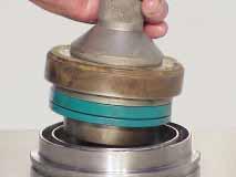
Figure 155 Using appropriate driver, install pinion seal. Reference tool drawing on page 89.

Figure 156 Apply thin continuous coat of Loctite 620 or equivalent to grease seal bore.
Figure 157 Using appropriate driver install grease seal and thrust washer. Reference tool drawing on page 88.
Figure 158 Install o-ring. Apply thin continuous coat of Loctite 620 or equivalent to pilot dia. of retainer as indicated. Figure 159 Apply Loctite 620 or equivalent to threads and install grease fitting.
Figure 160 Apply light coat of grease to sealing ring sealing surface in carrier bore.
Figure 161 Apply grease to thrust washer face and seal lips.
Loctite