I
I
BI619923
I @
CR194 Vacuum limitamp 4&I Ampere Control Extra-width Enclosure A special 34inch-wide enclosure is available for terminating shielded cable with stress cones, or for terminating more than one large cable per phase. The enclosure design permits space for termination of two 500-MCM cables per phase with stress cones* for motor and power leads. Figures 35 and 38 shbw the space available in this extra-width enclosure. Design is basically the same as the 26-inch-wide one-high, and all data and information in these instructions applicable to the 26-inch one-high design apply to the 34inch-wide enclosure.
Power Cable Termination In any installation, the cable should be prepared for termination in accordance with the instructions of the cable manufacturer. However, the following geneI-al recommendations are given for proper cable termination in Vacuum Limitamp equipment. 1. Pull in the cables in accordance with the panel outline diagl-am and position them for maximum clearance between phase, ground and other cable OI wire runs. Refer to Figure 60 of these instructions fo1 recommended location of incoming cables in a standard Limitamp controller-.
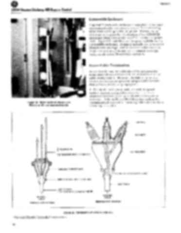
Figure 38. Motor cable terminations in 26-inch or 34-inch wide enclosures.
+
MAXIMUM
-
TERMINAL
_
BUSHINGS
OR POTHEAD
718” MAXIMUM
THROUGH-TYPE
OUTSIDE
POTHEAD WIPING
WIPING
SLEEVE
LEAD SHEATH 2 7/B” MAXIMUM
OR STUFFING
OUTSIDE
DIAMETER
TERMINAL.TYPE
POTHEAD
Figure 39. Termination
20
Electric
Lt-
LEAD
t INCOMING CABLE
INCOMING CABLE
*General
Termi-Kit@
stress cones.
SLEEVE
BOX
t
THROUGH-TYPE
BODY
DIAMETER
POTHEAD
of cable in potheads.
CABLE
OR STUFFING
BOX
