4 minute read
Dimensions

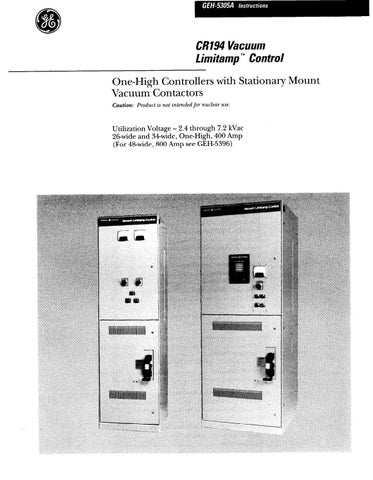
from Cat Electric Rope Shovel CR194 Vacuum Limitamp 400 Ampere Control GEH-5305A Instructions Operation &

Figure 17. Contactor engagement paw1 for mechanical interlock. Warning: There is no emergency condition that can just@ forc- ible operation of the manual isolator with the main contactor closed. The isolator must be operated only with the contactor Open.
All high-voltage doors are interlocked by mechanical interference mechanism that lock high-voltage doors closed until the disconnect switch is in the OPEN position. This is done to prevent exposure to high-voltage. In one-high controllers the bottom door covers the high- voltage compartment. Other high-voltage doors may be full height to cover high-voltage parts located in auxiliary sections. These devices may include reactors, autotrans- formers or control power transformers, etc.
Key interlocking is frequently used in lieu of mechanical interference mechanisms to lock high-voltage doors closed until power inside has been removed. Non- loadbreak switches are also key interlocked to prevent operation uncler load. In all cases of key interlocking, it is important to follow the operating sequence as de- scribed on the drawings furnished with the equipment.
On some one-high enclosure designs, a lowvoltage control panel mounted by hinges to the left side of the enclosure serves as a barrier to isolate the high-voltage control power tranSf(Jrlner and fuses. An interference latch, shown in Figure 54, prevents swinging this panel out until the high-voltage door is opened, thus ensuring that high-voltage power to the Control Power Trans- former is disconnected.
Figure 18. Blown fuse indicator shown in the NORMAL position. Auxiliary Enclosures
Many sizes of enclosures are furnished in Vacuum Limitamp control lineups for various purposes. Some are tabulated below:
Wound rotor, secondary contactor and resistor compartments Bus transitions to switchgear Bus transitions to transformers Cable entrance compartments Rectifier exciter compartments Starting reactor or autotransformer compartments Relay and metering compartments Instrument transformer compartments Manual switch compartments
Refer to Figure 60 for details.
Dimensions
Vacuum Limitamp controllers are normally 30-inches deep and SO-inches high. Width varies for one-high controllers, induction motors, synchronous motors, other special applications, or cable space requirements. Refer to Figure 60 for typical outline dimensions.
Power Fuses
Bolted EJ-2 type current-limiting power fuses are sup- plied as standard with Vacuum Limitamp controllers. These standard fuses are bolt-in type because the blown fuse,indicator and the trip bar that operates the anti- single phase contact block require precise alignment of the striker pin at the top of the fuse with the operators. Clip-in fuses are available as an option in 400 ampere to cover requirements for EJ-1 type fuses, but the “anti- single phase” indication/trip functions are not available with clip fuses. Coordination information for EJ-2 type fuses is available in GES-5000, and for EJ-1 type fuses, GES-5002. Interrupting ratings are shown on page 5 of these instructions. Figure 18 shows the top of the bolted power fuse assembly with the blown fuse indicators in the normal position.
Power Fuse Conversion Instructions
Bolt-in fuses used on Vacuum Limitamp and Air-break Limitamp may be field converted from one to the other by carefully following the instructions below.
Starting Autotransformers 8c Reactors
Reduced voltage controllers include a reactor or au- totransformer designed for starting duty in accordance with NEMA ICS2-214. The duty cycle generally fur- nished is for medium-duty applications which consist of three 30-second starts spaced 30-seconds apart followed by a one-hour rest. To prevent overheating and possible damage when applied on more severe duty (heavy duty) applications, special reactors or autotransformers must be specified. Thermostats are mounted on the reactor and transformer cores to offer protection against over- heating. These thermostats must be manually reset if tripped by high temperature.
SINGLE BARREL
CAT. NO. 55A212942P “A” CAT. NO. 218A4293P “A” cl
DOUBLE BARREL
qCAT. NO. 55A212942P “A” CAT. NO. 218A4293P “A”
BY CAREFULLY FOLLOWING THESE INSTRUC- TIONS, THE ABOVE FUSE VERSIONS MAY BE FIELD CONVERTED FROM ONE TO THE OTHER.
. LOOSEN BOTTOM BOLT (Y) WHILE INSURING FUSE BARREL
DOES NOT ROTATE (SEE CAUTION).
!. ROTATE BOTTOM STRAP (X) 180 DEGREES.
3. RETIGHTEN BOTTOM BOLT (B) TO 23-31 FTlLBS WHILE EN-
SURING THAT FUSE BARREL DOES NOT TURN.
CAUTION:DO NOT LOOSEN TOP BOLT OF FUSE. THIS WILL DAMAGE INTERNAL ELEMENTS OF FUSE.
BY CAREFULLY FOLLOWING THESE INSTRUC- TIONS, THE ABOVE FUSE VERSIONS MAY BE FIELD CONVERTED FROM ONE TO THE OTHER.
1. LOOSEN AND REMOVE BOTH BOTTOM BOLTS (Y) WHILE IN. SURING FUSE BARREL DOES NOT ROTATE (SEE CAUTION).
2. ROTATE BOTTOM STRAP (X) 180 DEGREES
3. REINSTALL BOTTOM BOLTS (Y) AND SPECIAL SPRING
WASHER (BELLEVILLE). RED PAINTED STRIPE ON WASHER
TO FACE TOWARD BOLT HEAD.
4. TIGHTEN BOTTOM BOLTS (B) TO 23-31 FTlLBS WHILE INSUF
ING THAT FUSE BARREL DOES NOT TURN.
CAUTION: DO NOT LOOSEN TOP BOLT OF FUSE. THIS WILL DAMAGE INTERNAL ELEMENTS OF FUSE.