2 minute read
Control Connections

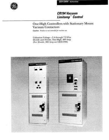
from Cat Electric Rope Shovel CR194 Vacuum Limitamp 400 Ampere Control GEH-5305A Instructions Operation &

Interlocked-armor, Non-shielded Cable
RUBBER-COVERED - Refer to Figure 42 for general information concerning termination. For details, refer to Figure 40. Note that rubber-covered cab!e requires only taping near the terminal and not back to the terminator fitting. However, if there is a possibility of oil coming in contact with the rubber insulation, it would be well to use a layer of Irrasila No. 42005 tape all the way back to the terminator fitting.
VARNISHED-CAMBRIC - Refer to Figure 42 for general information concerning termination. Note that var- nished-cambric cable requires taping back to the terminator fitting, since the individual conductors or “singles” have no braid.
Control Connections
Conduit for control wires should be brought in the areas as shown in the outlines. There is room in both the bottom and top for the control conduits to be brought into the enclosure. In all Vacuum Limitamp controllers, the control connections are made through a terminal board on the left side of the low-voltage control compart- ment. Refer to Figures 46 and 47 for details.
Interlocked-armor, Shielded Cable
Interlocked-armor, rubber-covered, and varnished- cambric insulated cables are sometimes shielded at ratings of 5 kV and below. If they should be, proceed to terminate as detailed for other types of shielded cables. Refer to Figure 43.
Termination of Shielded Cable
It is recommended that when shielded cable is used, “stress-relief cones” be built up at the cable terminations, or else General Electric Termi-Matic@ stress cones be used as shown in Figure 44 and Figure 45. This will relieve the electrical stress which occurs in the area around the termination of the ground shield. Whenever possible, the conduit should be brought in through the bottom. A maximum of one 500-MCM cable per phase may be terminated in one full-voltage starter section. When making shielded-cable terminations to Limitamp, the following procedure is recommended:
Use GE Termi-Matic system per Figure 45, or else build stress cones with tape as follows:
1. Mark the cable at least 10 inches from the terminal point.
2. Remove all shielding from the terminal end to this point, leaving sufficient ground strip to reach the nearest ground connection.
3. Proceed to build stress cones as prescribed by the cable manufacturer. Refer to Figure 43 and 44 for details.
4. Tie all of the ground strips together and fasten them to ground bus (if ordered) or to a large stud on the enclosing case. (See note on grounding under item on “Wire and Cable Entrance”.)
If the foregoing recommendations, along with the cable manufacturer’ s recommendations, are followed, the cable terminations should be satisfactory and reliable. These instructions apply to both rubber-covered and varnished-cambric insulated shielded cables.