2 minute read
Introduction

from Cat Electric Rope Shovel CR194 Vacuum Limitamp 400 Ampere Control GEH-5305A Instructions Operation &

Warning: Before any adjustments, servicing, parts replacement or any other act is performed requiring physical contact with the electrical working components or wiring of this equipment, power must be removed from all sources and all attached rotating equipment must have come to a complete stop.
lJser@rsonnel must be completely familiar with the following operating and maintenance instructions before attempting to service this equipment.
Warning: The vacuum interrupter integrity test should be performed before the high-voltage, vacuum contactor is energized for the first time and each time the contactor is returned to service after maintenance, adjustment, or repair.
Failure to perform this test may result in serious injury or death.
Introduction
Vacuum Limitamp controllers are designed to meet NEMA ICS2-324 “AC General Purpose High-voltage Class E Controllers” and UL 347 requirements, and may be described as metal-enclosed high-interrupting capacity, vacuum-contactor-type starter equipments with manual isolation. Individual starters and controllers are de- signed for specific applications; the components and functions being dictated by the Purchaser specifications and needs. Controllers may be fused or unfused. The essential control functions for all types of a-c motors consist of starting, stopping, and overload protection. Vacuum Limitamp controllers also include short-circuit protection, but other functions are provided in each controller as they are applicable to the type of motor being controlled (such as synchronous and wound-rotor motors). Also, special functions are provided in great variety as may be required for particular applications.
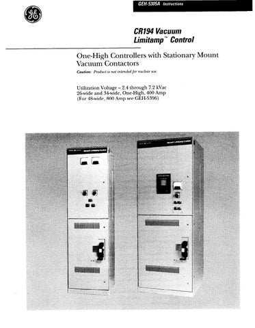
These instructions were prepared as a guide to handling, installation, operation and maintenance of all one-high, 400 Amp types of Vacuum Limitamp controllers. This includes the 26-inch wide one-high and the 34inch wide one-high controller. Figure 1 shows a 26-inch wide controller and Figure 2 shows a 34inch wide synchro- nous controller.
The intent of these instructions is to give the Purchaser the necessary general information to identify his control- ler as to type and function, to describe suggested methods of installation, and to demonstrate some techniques of operation and maintenance. The Pur- chaser should interpret these instructions for applicability to his particular controller by referring to the nameplate data on the controller and to the electri- cal diagrams supplied with the controller.
If the controller is for a synchronous motor, these instructions should be used with GEH-5201. For applica- tions questions refer to GET-6840. For details on high-voltage contactor refer to GEH-5306.