3 minute read
Preventive Maintenance Guide

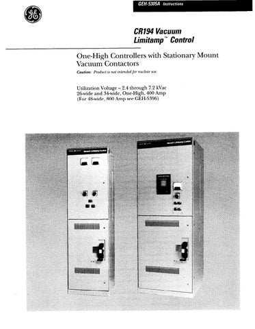
from Cat Electric Rope Shovel CR194 Vacuum Limitamp 400 Ampere Control GEH-5305A Instructions Operation &

Figure 59. Method of connecting test leads to interrupter for vacuum integrity test.
3. Reverse the leads and repeat the test.
4. If no breakdown occurs the interrupter is in accept- able condition. If a breakdown occurs the interrupter should be replaced. Refer to the “Interrupter Replace- ment” section in GEH-5306.
Note: No attempt should be made to tq to compare the condi-
tion of one vacuum interrupte-r with another nor to correlate the condition of any interrupter to low ualub of DC leakage cur-
rent. There is no significant correlation.
5. After the high potential voltage is removed from the interrupters, the metal end caps of the interrupters should be discharged with a grounding stick to remove any residual electrical charge.
6. Make sure that all connections are tightened properly to 16 lb.-ft. Reconnect load cables and replace CPT fuses.
Preventive Maintenance Guide
Warning: Before performing any preventive maintenance on the Vacuum Limitamp controller all power must be removed from the equipment and all rotating equipment must have coasted to a complete stop.
Maximum trouble-free service from Vacuum Limitamp controllers requires periodic inspection, preventive maintenance, and periodic cleaning. A definite sched- ule should be maintained for inspection, the frequency depending upon operating conditions. Preventive maintenance activity should then be established as the result of periodic inspection. In these routine inspections, four basic categories of deteriorating influences should be kept in mind:
la. The effect of foreign material: Dirt and dust from the environment such as wood fibers, coal dust, cement, lamp black, lint.
lb. The effect of chemicals in the atmosphere: such as sulfur dioxide, chlorine, some hydrocarbons and salt water.
2. Mechanical wear and fatigue on all moving parts.
3. Heat.
4. Loose joints and connections.
5. Perform vacuum interrupter integrity test as de- scribed in these instructions.
Follow directions in these instructions for obtaining access to all sections of the controller including high- voltage door interlocking. Also, refer to GEH-5306 for directions relative to inspection of the high-voltage contactor.
The following are some specific recommendations:
1. Check for cleanliness generally, but particularly for accumulation of any foreign material on insulators. Voltage failures can result from tracking across insula- tion surfaces when they are dirty. The primary circuit insulation on the controller may be checked phase to phase and phase to ground using a 2500 volt megger.
2. Check for abrasive material accumulated in the isolating mechanism and mechanical interlock bearing and cam surfaces.
3. Check for buildup of dust or dirt which would reduce any air or surface voltage clearances.
4. Excessive heat can cause wire and cable insulation breakdown. Therefore, check for any evidence of melting, discoloring, deterioration of wire and cable.
5. The isolating mechanism has a life expectancy of approximately 6000 operations. If the application is such that the mechanism is operated more than twice each day, then the mechanism should be checked at the end of each 1000 operations, otherwise a yearly inspec- tion is recommended.
6. Periodic checks of dimensions of the isolating mecha- nism and mechanical interlocks is strongly recom- mended. Follow the section in these instructions entitled “ISOLATING MECHANISM AND MECHANI- CAL INTERLOCK”.
7. When any part of the isolating mechanism and mechanical interlock is replaced, all dimensions and checking procedures referred to under No. 6 above should be followed to be sure the system is in normal working order.
26” WIDE
TOP V;Ei
L.“. SIDE YIEU
A- 1000 #
,+--26-
34” WIDE
l-3/8 TOP “IEU
L.H. SIDE VlEU
AUXILIARY
TOP VIEU TOP VIEU
7FT 6
NOTE: B - INCOMING POWER TERMINAL CONNECTION Bl -AC POWER BUS * - INDICATES TERMINAL LOCATION - APPROX. FOR CABLE LENGTH
C - CONTROL LEAD TERMINAL BOARD A -APPROXIMATE UNCRATED WEIGHT D - MOTOR LEAD TERMINAL CONNECTION -ADD 5 PERCENT FOR DOMESTIC SHIPPING WEIGHT E - GROUND BUS TERMINAL CONNECTION -ADD 20 PERCENT FOR EXPORT SHIPPING WEIGHT F - GROUND TERMINAL CONNECTION G - SPACE REQUIRED TO OPEN DOORS 90 DEGREES J - MOUNTING HOLES FOR l/2 IN. DIA. ANCHOR BOLTS K - SPACE AVAILABLE FOR INCOMING CONDUIT M - RECOMMENDED POSITION FOR INCOMING MOTOR CONDUIT N - RECOMMENDED POSITION FOR INCOMING CONTROL CONDUIT P - RECOMMENDED POSITION FOR INCOMING POWER CONDUIT
BI619923
BI619923
These instructions do not purport to cover all details or variations in equipment nor to provide for every possible contingency to be met in connection with installation, operation or maintenance. Should further information be desired or should particular problems arise which are not covered sufficiently for the purchaser’ s purposes, the matter should be referred to the GE Company.