5 minute read
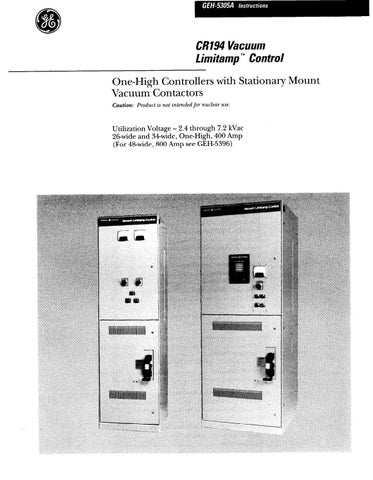
Vacuum Contactor

from Cat Electric Rope Shovel CR194 Vacuum Limitamp 400 Ampere Control GEH-5305A Instructions Operation &

Door-Defeater Latch
Warning: The following steps should only be taken as a last
resort to enter a malfunctioning controller. It is imperative that all power to the main bus be removed before proceeding.
IN CASE OF EMERGENCY, remove all power to the controller; then the high-voltage door may be opened with the contactor in the closed position and with the isolating switch closed by using the hex-head bolts, located to the lower left of the isolating-switch handle, as follows:
Warning: Do not proceed unless all power to the controller is
removed. Doors must not be opened with the power connected to
the bus.
1. Turn the door latches % turn counterclockwise.
2. Remove the right-hand hex-head bolt, as shown in Figure 52.
3. Turn the left-hand bolt % turn counterclockwise. Figure 53 shows the bolts from the inside. The door may then be opened.
Warning: Defeating the door interlock leaves the controller connected to the bus. The bus power must be removed.
On some one-high enclosures, the low-voltage control panel serves as a barrier to isolate the high-voltage control-power transformer and fuses. An interference pin, shown in Figure 54, prevents swinging this low- voltage panel out until the high-voltage door is opened.
Inspection, Maintenance, and Servicing
Vacuum Contactor
Complete maintenance and adjustment instructions for the high-voltage contactors are presented in GEH-5306. Refer to that instruction for all problems of servicing and adjust- ing; and to the proper renewal parts bulletin for renewal parts.
Contactor tip life depends on the severity of the service, but in any case, it is recommended that the contactor tip wear be checked at least once a year or in very high duty cycle operations, after every 250,000 operations.
Isolating Mechanism and Mechanical Interlock
Warning: Under no circumstances should the isolation switch be inspected or adjusted with power applied to the main bus.
The quick-make quick-break isolation switch assembly is adjusted and tested at the factory. Under normal circumstances the switch does not need adjustment, however, if conditions require it the switch may be adjusted in the field. To adjust the isolating switch the following steps should be followed:
Warning: All power must be removed from the main bus before attempting to adjust the isolating switch mechanism.
1. After removing all power to the controller, and as described in steps 1 & 2 of the Mechanical Operation Check, rotate the isolating switch handle to the ON position. Then remove the fixed barrier (Figure 33) by removing the retaining screws that hold it in place. Retain the hardware for reassembly.
Some of the barrier mounting hardware is nylon type hardware. Note the location of these parts so they may be reassembled properly.
2. Near the end of each switch blade assembly, an adjusting nut is located along with a Belleville washer type spring. To adjust the blade pressure the nut must be adjusted. Loosen the small set screw located on each of the retaining nuts to enable adjustment.
3. Loosen the adjusting nut at the top of the blades. With your fingers retighten the nut until all the slack is out between the blades, stationary contact, spring washer & nut, then tighten an additional % (one-eighth) turn. This procedure provides the necessary 0.005 inch spring compression of the blades.
4. Tighten the set screw on the nut to lock the adjust- ment in position. Use caution to prevent turning the nut on the main screw while tightening the set screw.
5. When the adjustment is complete for all three phases, rotate the isolating switch handle to the OFF position. Then, apply a thin coating of Mobil Temp SHG32 grease to the contact surfaces of the male stab portion of the disconnect.
To properly adjust the pivot point Belleville washer type spring, return the isolating switch handle to the ON position per step 1 above. Then, follow the steps below:
1. On each phase, loosen the set screw on the pivot point adjusting nut.
2. Loosen the adjusting nut and then retighten using your fingers until the nut is just snug and no side play of the parts is evident.
3. Using wrenches tighten the adjusting nut an addi- tional one-half (%) turn and tighten the set screw to hold the adjustment in place.
4. Rotate the isolating switch handle to the OFF position, then reinstall the isolator switch barrier. If necessary the viewing window may be cleaned before reinstallation of the barrier. Use a soft cloth and a mild soap and water solution or a commercial cleaner such as Windex or other similar cleaner.
Warning: Severe injury or death may result af the equipment is energized with the mechanical interlocks defeated. Remove all
power from the equipment before defeating any of the mechanical
interlocking mechanisms.
f-----
DOOR INTERLOCK BAR I
I
ADJUST STOP NUT BEHIND DOOR SO THAT l LATCH MAY PIVOT FREELY. LOOK-THROUGH
LATCH ASSEMBLY
FRONT VIEW WARNING: Defeating the door interlock leaves the controller connected to the bus. The bus power must be removed.
NOTE
To check if sufficient (or safe) interlocking between door and door interlock bar exists, the following should be done:
A. Open high-voltage door.
B. With the door open, close the isolator switch by manually depressing the door operated release. See Figure 49.
C. Close door against interlock bar.
D. Look through door cutout below handle and visually determine if there is a minimum of 0.50-inch overlap (see sketch).
E. For a final check, close the door, close the disconnect switch, and try to pull the door open. The door should not open.
Figure 56. Checking procedures for mechanical door interlock.
CONTROL POWER INTERLOCK
6
I I, 1 +-+I
f
PUSHER ROD 1 __ 417
1 t
I’ WARNING: Defeating the door interlock leaves the controller connected to the bus. The bus power must be removed.
NOTE
1. Set 0.12-inch gap (as shown) with pusher extended (out position). See 0.60-inch reference.
2. Then, check the interlock operation with the pusher depressed.
3. Both contacts must be open and have a contact gap of at least % inch.
4. Insure the pusher pops out fully (see 0.60- inch reference) in both the down (off) and up (on) positions.