5 minute read
Power Cable Termination

from Cat Electric Rope Shovel CR194 Vacuum Limitamp 400 Ampere Control GEH-5305A Instructions Operation &

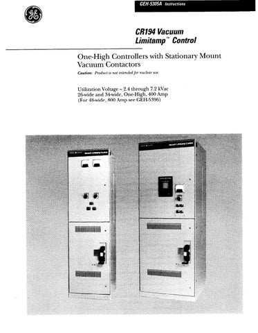
Figure 38. Motor cable terminations in 26-inch or 34-inch wide enclosures. Extra-width Enclosure
A special 34inch-wide enclosure is available for terminat- ing shielded cable with stress cones, or for terminating more than one large cable per phase. The enclosure design permits space for termination of two 500-MCM cables per phase with stress cones* for motor and power leads. Figures 35 and 38 shbw the space available in this extra-width enclosure. Design is basically the same as the 26-inch-wide one-high, and all data and information in these instructions applicable to the 26-inch one-high design apply to the 34inch-wide enclosure.
Power Cable Termination
In any installation, the cable should be prepared for termination in accordance with the instructions of the cable manufacturer. However, the following geneI-al recommendations are given for proper cable termina- tion in Vacuum Limitamp equipment.
1. Pull in the cables in accordance with the panel outline diagl-am and position them for maximum clearance between phase, ground and other cable OI wire runs. Refer to Figure 60 of these instructions fo1 recommended location of incoming cables in a standard Limitamp controller-.
+ MAXIMUM OR
718” MAXIMUM OUTSIDE DIAMETER - TERMINAL
_ BUSHINGS
POTHEAD BODY
t
INCOMING CABLE
THROUGH-TYPE POTHEAD THROUGH-TYPE POTHEAD
WIPING SLEEVE OR STUFFING BOX
LEAD SHEATH 2 7/B” MAXIMUM OUTSIDE DIAMETER WIPING SLEEVE OR STUFFING BOX
Lt- LEAD CABLE
t INCOMING
CABLE
TERMINAL.TYPE POTHEAD
Figure 39. Termination of cable in potheads.
2. Prepare the cable for termination in accordance with the manufacturer’ s instructions. For suggested terminat- ing methods, see pages 20 through 23 and Figures 39 through 45.
3. Bolt the cable terminals to the bus or other point of termination.
GE IRRASIL” NO. 42005 TAPE
OUTER LAYER IRRASIL TAPE
NOTE:
FOR DETAILS OF END
SEAL SEE FIG. 40 FOR
RUBBER CABLE AND
FIG. 41 FOR VARNISHED
CAMBRIC CABLE.
CABLE TERMINAT FITTING COPPER LUG
GE NO. 8380 TAPE INSIDE FOR RUBBER OR NO. 992 VC TAPE FOR VARNISHED CAMBRIC IS RECOMMENDED. ALTERNATE: BUILD ENTIRE END SEAL WITH GE IRRASILa TAPE.
FILL WITH SEALING COMPOUND
SPLICE TAPE
Figure 40. Termination of rubber-insulated, non-shielded, non-lead-covered, 5000~volt cable.
L
Figure 42. Termination of interlocked-armor, non-shielded, 5OW-volt cable.
Irroril No.4200
CABLE INNER INSULATION CABLE TAPE
1. Cut cable to proper length leaving conductor sufficiently long to extend into the terminal lug. 2. Remove braid, tape, and inner insulation and expose the conductor end for a distance of one inch plus the length of conductor to go into the terminal lug. 3. Attach terminal to conductor.
4. Taper the insulation as shown. 5. Remove the braid and tape, if any, six inches from the lug, exposing the insulation. Leave one-half inch of original cable tape extending beyond the cutback braid. 6. Apply the end seal using GE Irrasil@ electrical tape. Ob- tain a smooth wrapping but do not stretch tape more than necessary. 7. Bind down end of braid and tape, if any, with lrrasil tape as shown on drawing. 6. Apply two layers half-lap of GE Irrasil@ tape over-all from lug to exposed braid.
Figure 41. Termination of varnished-cambric-insulated, non-shielded, non-lead-covered, 5000-volt cable. Figure 43. Termination of interlocked-armor, shielded, 5000-volt cable.
COPPER SHIELDING 1” BRAID-GROUNDED TO STRUCTURE OR ARMOR.
FILL WITH SEALING COMPOUN
INSULATIN
CABLE ARMOR STRESS CONE
CABLE TERMINATOR
4. If contact between the cable and an adjacent bus cannot be avoided, as may be the case with the two 500- MCM cables per phase, tape the bus in the immediate vicinity of the cable contact point so that the surface creepage distance from the cable to the bare bus bar is at least three inches. Thus, the surface creepage from the bare bus where the cable terminates, to the bare part of the bus where the cable touches, will be at least seven inches. The thickness of tape on the bus should be approximately Xr inch. General Electric No. 8380 tape is recommended for most of the buildup and General Electric No. 42005 Irrasil@ tape is recommended over-all.
5. Where more than two 500-MCM cables per phase are required, they should be brought into different sections,
GE NO. 8380 TAPE INSIDE FOR RUBBER OR NO. 992 VC TAPE FOR VARNISHED CAMBRIC IS RECOMMENDED. ALTERNATE: BUILD ENTIRE END SEAL WITH GE IRRASIL” NO. 42005 TAPE
CABLE INSULATION
GE NO. 8380 TAPE
NO. 19 AWG TINNED COPPER WIRE
GE IRRASILS NO. 42005 TAPE
SHIELDING TAPE
GE NO. 8380 TAPE
GE IRRASIL” NO. 42005 TAPE
Figure 44. Termination of shielded, 5000-volt cable showing stress-cone construction.
1. Maintains tight fit under load cycling and all cable operating conditions. 2. Track-proof insulating EPDM rubber. 3. Heavily-insulated shield edge protects high stress area of stress cone. 4. High conductivity semi- conducting rubber relieves electrical stress. 5. Internal step positions stress cone properly on cable shield. 6. Ground clamp provides positive ground. f -1
r?
CONDUCTOR
Figure 45. TERMI-MATIC preformed stress cones (5 kv).
or an incoming line compartment must be provided. If the two 500-MCM cables must be terminated with stress cones, a cable entrance compartment must be ordered.
6. Run all the low-voltage wires so as to avoid any possible con tact with high-voltage lines.
Termination of Lead-covered Cable
Termination of lead-covered cable requires the use of potheads (see Figure 39.) The pothead manufacturer’ s instructions should be followed in terminating the cable at the pothead. Standard Limitamp starters have space for locating one pothead of the pull-through type which accommodates up to and including 2/O, three-conduc- tor, 5000-volt cable. In this type of pothead, the three conductors of the cable are fanned out within the pothead ant1 pass completely through it, with the pothead sealing and terminating the lead covering. Foi- larger cables, potheads with terminating bushings are required. In this case, 01. when more than one pull- through type is required, special cable entrance compartments are available.
Through-type potheads are satisfxtoi-): for varnished- cambric cable indoors. Paper--insulated cables are more hygroscopic and, since the only thing protecting the individual conductors from moisture is tape on the surface, high humidity might cause difficulty. Terminal- type potheads are r-equired for papeGnsulated cable.
Termination of Pothead Cable
The instructions for terminating lead-covered cable by using potheads apply as well to those terminations of other types of cable where potheads may be desired.
Termination on Non-shielded, Non-lead- covered Cable
This cable is generally run through rigid conduit or cable raceways and brought into the enclosure by the use of conventional cable clamps and conduit fittings. Refer to Figures 40 and 41 for termination details.
Termination of Interlocked-armor Cable
Interlocked-armor cable is terminated by means of specially designed cable fittings. These terminators consist generally of mounting bracket, armor clamp, and supporting base and bushing, with various modifications available for special types of sealing.