BI619923
, I I @
CR194Vacuum limitamp 4lWAmpere Control There is no emergency condition that can just@ forcible operation of the manual isolator with the main contactor closed. The isolator must be operated only with the contactor Open.
Warning:
All high-voltage doors are interlocked by mechanical interference mechanism that lock high-voltage doors closed until the disconnect switch is in the OPEN position. This is done to prevent exposure to high-voltage. In one-high controllers the bottom door covers the highvoltage compartment. Other high-voltage doors may be full height to cover high-voltage parts located in auxiliary sections. These devices may include reactors, autotransformers or control power transformers, etc. Key interlocking is frequently used in lieu of mechanical interference mechanisms to lock high-voltage doors closed until power inside has been removed. Nonloadbreak switches are also key interlocked to prevent operation uncler load. In all cases of key interlocking, it is important to follow the operating sequence as described on the drawings furnished with the equipment.
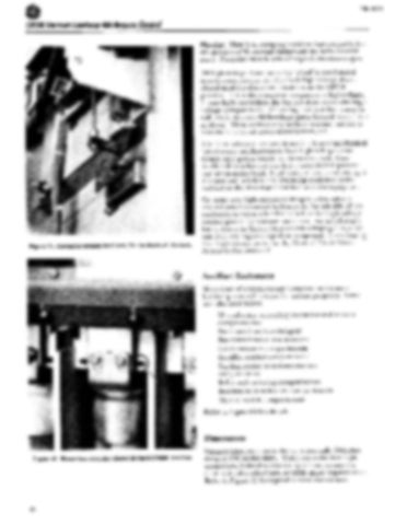
Figure 17. Contactor engagement
paw1 for mechanical
interlock.
On some one-high enclosure designs, a lowvoltage control panel mounted by hinges to the left side of the enclosure serves as a barrier to isolate the high-voltage control power tranSf(Jrlner and fuses. An interference latch, shown in Figure 54, prevents swinging this panel out until the high-voltage door is opened, thus ensuring that high-voltage power to the Control Power Transformer is disconnected.
Auxiliary Enclosures Many sizes of enclosures are furnished in Vacuum Limitamp control lineups for various purposes. Some are tabulated below: Wound rotor, compartments
secondary
contactor
Bus transitions
to switchgear
Bus transitions
to transformers
Cable
compartments
entrance
Rectifier
exciter
and resistor
compartments
Starting reactor or autotransformer compartments Relay and metering Instrument Manual Refer
compartments
transformer
compartments
switch compartments
to Figure
60 for details.
Dimensions Figure 18. Blown fuse indicator shown in the NORMAL
10
position.
Vacuum Limitamp controllers are normally 30-inches deep and SO-inches high. Width varies for one-high controllers, induction motors, synchronous motors, other special applications, or cable space requirements. Refer to Figure 60 for typical outline dimensions.
