Section F. Adjustments
Belarus - 90/92
Operating manual
PTO adjustment Adjustment of rear PTO control linkage
During assembly at the manufacturer, or after repair (for example, after replacing brake bands), make adjustment of the control linkage in the following order: 1. Put eccentric axle 15 to initial position, so that flat “C” (fig. 2) is to the right vertically, and fix it with stop plate (17) and bolt (16); 2. Disconnect tie-rod 4 (fig. 1); 3. Unscrew bolt 9 to release spring 6; To make unit disassembly safe make sure that, when unscrewing bolt (9), upper cup (7) is in permanent contact with it until the spring unclamps fully. 4. Dismount cover of the rear axle hatch to get access to screws 13;
5. Fix lever 11 in neutral position by introducing bolt 10 (М10X60) in diameter inside lever opening, and opening in the rear axle body, corresponding to it; 6. Remove stop plate 26 (fig. 2), screw up in turn adjusting screws 21 with torque from 8 to 10 N•m, then unscrew each screw by 2 turns and it is necessary screw the screws so that screw heads are placed parallel to direct axis of the tractor; 7. Holding lever 11 in neutral position remove bolt 10 (М10×60); 8. Screw bolt 9, aiming its toe inside recess of cup cover 7 up to size "А", equal to 26+2 mm and fix by nut 8; 9. Shift lever 11 back to position “ON”;
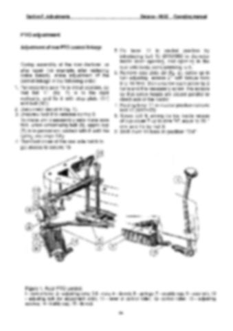
Figure 1. Rear PTO control: I - control lever; 2 - adjusting yoke; 3,8 - nuts; 4 - tie-rod; 6 - springs; 7 - outside cup; 9 - stop bolt; 10 - adjusting bolt (for adjustment only); 11 - lever of control roller; 12- control roller; 13 - adjusting screws; 14 - inside cup; 15 - tie-rod. 65


