
29 minute read
Every 10 working hours or daily - Fulfill foregoing maintenance operations plus following operations every


Daily maintenance (DM) after every 10 hours of operation or daily
Operation 1. Oil level in engine casing
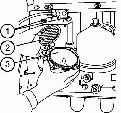
Shut down the engine, wait for 15 minutes and check oil level. Oil level should be between lower and upper probe (3) marks. If necessary, remove cover (2) of oil filling neck (1) and fill oil up to the top mark of probe (3).
IMPORTANT! Do not operate engine with oil level below lower mark of oil gauge.
IMPORTANT! Do not fill oil above the level of oil gauge upper mark. Surplus oil will burn, making false impression of large oil consumption due to burning loss.
Operation 2. Level of cooling fluid in engine radiator
Take off the radiator plug and check level of cooling fluid, which should be 50-60 mm below the upper end face of filling neck (1). If necessary, fill fluid up to required level.
IMPORTANT! Do not allow level recession below more than 100 mm of the top end face of the filling neck.
WARRNING! Engine cooling system is functioning under pressure maintained by means of valve in the radiator plug. It is dangerous to take off plug on hot diesel. Let the engine cool down, cover the plug with thick cloth, and slowly opening the plug reduce pressure in the system before taking off the plug completely. Beware burns by hot fluid.

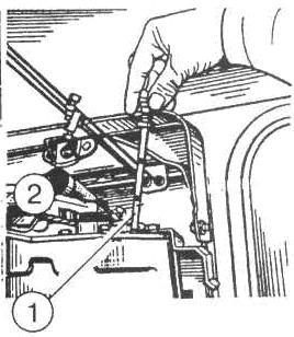
Operation 3. Oil level in hydraulic system tank
NOTE: Before checking oil level, put tractor on level horizontal terrain. Shut down diesel and break the tractor with parking brake.
Check oil level on oil-metering glass (1) on the left-hand side of hydraulic assemblies’ casing. The level should be between marks “0” and “P”. If necessary, fill oil up to mark “P” ±5mm, having unscrewed threaded plug (2).
NOTE: When machines with large oil consumption are used, fill oil up to the lever of top mark «С». All hydraulic cylinders, including rear cylinder, should have rods drawn in.
Operation 3а. Steering
Check operational capability of steering system. Look over, check aurally, test in running order.
Perform operations of the previous maintenance and those given below:
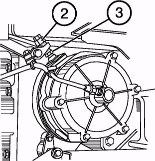
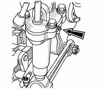
Operation 4. Level and state of oil in air purifier sump of engine
Loosen two nuts (1) and take off sump (2) of air purifier(3). Check oil level in the sump, which should be at the ring belt level «А». Add oil, if necessary. If oil contains dirt and water, replace oil.
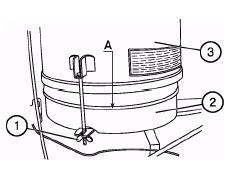
ATTENTION! Do not overfill sump with oil above ring belt «А», as this may lead to oil getting inside engine combustion chamber and make false impression of excessive oil consumption due to burning loss.
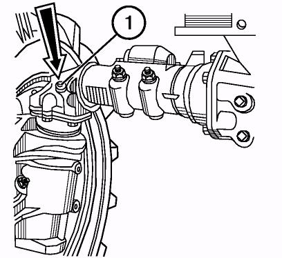
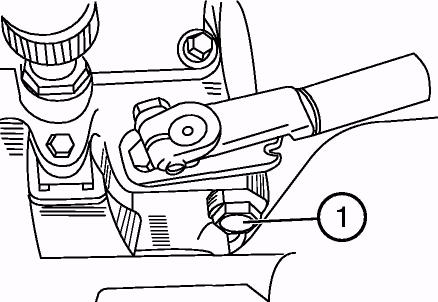
Operation 5. Oil level in FDA casings of upper coned pairs with bevel gear speed reducers.
Check the oil level, which should be at lower edge of oil filler neck (1). Fill oil up, if necessary.
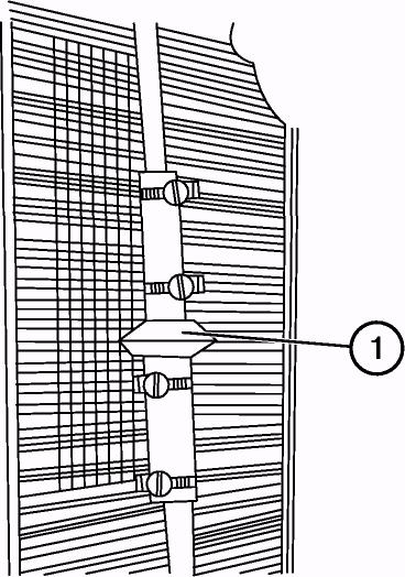
Operation 6. Draining sediment from fuel tanks and course fuel filter.
Open drain plugs (1) of fuel tanks (2) and drain plug (3) of filter. Drain sediment until pure fuel comes out. Drain sediment in special container and dispose it correctly. Close drain valves after pure fuel without water and dirt comes out.
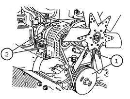
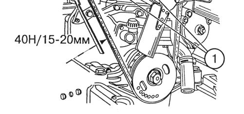
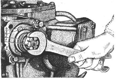
Operation 7. Checking tension of engine cooling system fan drive belt
Check the belt for signs of wear or damage. Replace it, if necessary. To check alternator belt tension apply force of 40 N (4 kgf) in the middle of branch between pulleys of generator and water pump (1). The sag should be in the range of 6…10 mm. If necessary, adjust belt tension by turning generator casing, having in advance loosened and then tightened generator fastening bolts. NOTE: By installation of usual generator panel the belt tension shall be checked between pulleys of generator and crankshaft. The sag should be in the range of 15…20 mm at force of 40 N in the middle of branch.

Operation 8. Rear wheel hubs.
• Check tightness and, if necessary, tighten bolts (1) fastening rear wheels’ hubs (four bolts for each hub) using torque wrench. Torque should be 300…400 N/m (30…40 kgf/m). • Check and, if necessary, torque nuts: • Front wheels to 200...250 N/m • Rear wheels to 300...350N/m • Disks to rims to 180...240 N/m

40N 6…10mm
40N 15…20mm

Operation 9. Air pressure in tires
Check the state of tread and air pressure in tires. If necessary, adjust pressure in accordance with recommendations set forth in the present “Manual”.
Operation 10. Lubricating bearing of clutch release yoke
Take off plug (1) on the left side of clutch casing. Using syringe make 4…6 injections of grease LITOL-24 via grease cup screwed in shifter casing for lubrication of squeeze bearing. NOTE: Do not inject too much grease, as excessive grease will accumulate inside clutch casing and can get on friction surface of driven disk friction lining.
Operation 11. Storage batteries
WARNING: Batteries contain sulphuric acid, which causes great burns when in contact with skin. Beware acid getting on hands skin, in eyes, on cloths. When acid is spilled on body parts, wash them profusely with a flow of pure water. When acid gets inside, drink large amount of water or milk.
When in contact with eye mucosa, rinse it with large amount of water for 15 minutes, and then ask for medical assistance. Avoid contact of spark or
flame with electrolyte, as this may result in explosion. Charge batteries in ventilated rooms. Put on protective goggles and gloves when servicing batteries. Keep batteries clean and dry. Make sure, batteries are properly fastened. Before taking off plugs, clean adjacent surfaces. Check level of electrolyte. It should be

12…15 mm higher of protective mesh (or between level marks on transparent battery housing). If necessary, add distilled water. Before adding distilled water check electrolyte density in each cell jar of the battery. If necessary, additionally charge storage batteries. Check terminals (2) under sheathes (A) and plugs (1) for cleanness. If necessary, grease terminals (2) with technical cup grease.
Operation 12. Oil level control in intermediate bearing of FDA cardan drive.
Check oil level in intermediate bearing. Fill oil up to lower mark of filling hole, which is blanked off with plug (1), if necessary.

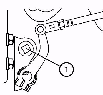
'Operation 13. Checking plays of steering joints
After each 250 hours of operation check steering joints by hand force shaking or wheel turning.
To regulate steering joints, please do the following:
а) Take off locking wire (2) from the lug 3. b) Screw up threaded plug (1) in a way to eliminate clearance in joint connection. c) Lock the plug with wire.
NOTE: If backlash can not be eliminated by screwing up threaded plugs, disassembly the joint and replace worn out parts.
'Operation 13а. Checking of oil level in casing of steering booster
Remove plug 2 and take off oil level gauge 1 from hydraulic booster casing. Oil should be at the upper mark of the oil level gauge 1.When low oil level, fill oil up to required level.
* Provide maintenance operation after every 250 hours of operation.

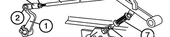
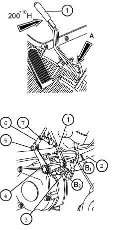
*Operation 14. Adjusting free travel of clutch pedal
IMPORTANT! Too great free pedal travel does not allow to fully disengage the clutch and makes gears shifting more difficult. No free travel of the pedal causes wear of friction facings and overheat of clutch components.
• To adjust free clutch pedal travel: • Unlock and pull out pin (2), having disconnected tie-rod (5) from lever (1) • Loose check nut (4). • Unscrew bolt (8) so that rod of pedal (6) moved upwards to the end to cabin floor. • Turn lever (1) anti clockwise to the end of squeeze bearing of levers. • By rotating yoke (3), align openings in yoke and lever (1), then screw yoke in tie-rod (5) by 5…5.5 turns (i.e. shorten the tie-rod). Connect yoke (3) to lever (1) by means of pin (2). • Assembly lever mechanism of clutch pedal in a reverse order.
IMPORTANT! Make sure, that clutch pedal reliably returns back to the end of the floor, when shifted by full travel magnitude. Otherwise adjust spring force of servo (7) with a help of bolt (8) or change position of the arm (9) by its turning toward the axle of bolts fastening.


___________________________________ * Provide maintenance operation after every 250 hours of operation.
Perform operations of the previous maintenance and the following operations:
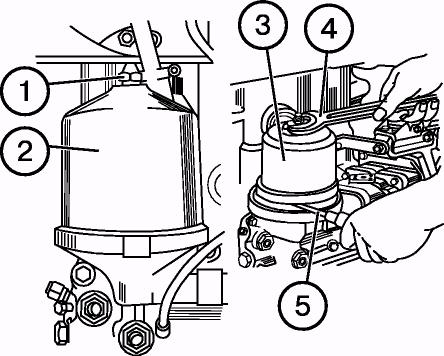
Operation 15. Centrifugal oil filter of engine
• Take off nut (1) and cap (2). • Insert a screwdriver (5) or rod between filter casing and rotor bottom to stop rotor (3) from rotating, and turning rotor nut using key (4) take off rotor cup (3). • Remove cover (6), impeller (7) and filtering mesh (8) of rotor. If necessary, clean and wash the mesh. • Use non-metal scraper to remove deposits off inside walls of rotor cup. • Clean all parts, wash them in diesel fuel and blow off with compressed air. • Assembly the filter by performing disassembly operations in the reverse order. Before assembling cup and rotor casing, grease sealing
«О»-ring with motor oil. • Align balance marks on the cup and rotor casing. Screw in cup fixing nut with small effort until the cup fully slides on the rotor. • Rotor should rotate free and without jamming. • Reinstall cup (2) and torque nut (1) to 35...50 N m (3,5…5,0 kgf-m). .
NOTE: After engine stoppage, for 30-60 seconds noise of rotating rotor should be audible. It means that filter functions properly.
Operation 16. Changing oil in engine
• Warm up engine up to normal operation temperature (at least 70°С). • Put tractor on even terrain, shut down engine and engage tractor parking brake. • Remove cover (2) of oil filling neck and unscrew drain plug (4).
ATTENTION! Be careful to avoid contact with hot oil.
Drain oil in proper container for storage of used oils. • Put drain plug (4) in place and through oil filling neck (1) fill fresh motor oil (M8DM, М-8G2, М-8G2К in winter, and М10DМ, М-10G2, М-10G2к in summer) up the top mark of oil measuring rod (3). • Put cover (2) of filling neck in its place. • Start the engine and let it operate for 1-2 minutes. • In 10 minutes after engine stoppage check oil level using oil measuring rod (3). • If necessary, fill oil up to the required level.


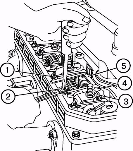
Operation 17. Checking clearance between valves and rockers
NOTE: Check clearances on cold engine, having checked in advance the tightness of cylinders’ head bolts Observe the following sequence of adjustment: • Take off caps of cylinders’ head covers and check fastening of rockers’ axle posts. Torque of nuts is 60.. 90
N•m (6... 9 kgf•m). • Turn crankshaft through until timing overlap in the first cylinder (inlet valve starts opening, and the outlet valve starts closing), and adjust clearances in valves 4, 6, 7 and 8 (counting from the fan). • To adjust clearance loosen check nut (1) of screw (2), put probe (5) between end face of valve rod (3) and rocker pin(4), then screwing in or out screw (2) set required clearance by probe.
Value of clearance between rocker pin and end face of valve rod on cold diesel for inlet and outlet valves is shown in the table:
Belarus 90/92 Inlet valves Outlet valves 0,20...0,35 0,20...0,35 • Turn through crankshaft by 360°, having set timing overlap in the fourth cylinder, and adjust clearances in valves 1, 2, 3 and 5, as shown above.
• After adjusting clearances, tighten check nuts (1) and put removed parts in place.
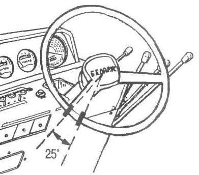
Operation 18. Play of the steering wheel
With engine in operation the steering wheel play should not exceed 25°. Otherwise, check and eliminate plays in joints of hydraulic cylinders, steering tie-rod.
Operation 19. Adjustment of wheel and parking brakes. Adjustment of brake valve and pressure regulator valve of pneumatic system.
Adjust brakes in the following way: a) Loosen check nut (3) of adjusting bolts (2). b) Screw in or out the bolt (2) so that full travel of the right brake pedal of wheel brake should be within 115...125 mm when applying effort of 120..130 N (12 kgf), and of the left brake pedal by 5-20 mm less for synchronous braking action in interlocked position. Do not allow less brakes pedal travel than is given above, because it will lead to the early wear and brakes overheating; c) Draw up the safety nuts (3). Lock the pedal with locking bar (1) and check synchronism of right- and left-hand brakes engagement during movement (no more than 1 m according to the mark). If grease ingress in brake, it lead to disk greasing and to decrease of force of friction between their work faces, brakes “do not hold”. In this case disassembly the brake, remove oil leak and rinse greasy disks with petrol, left them dry for 5-8 min. Adjust pedals travel after mounting.
120 +10N

To adjust parking brake:
Put the tractor on the even surface, shut down the diesel and lock rear wheels from front and back sides and do the following: a) Shift lever (1) to extreme front (disengaged) position. b) Loosen check nut of adjusting bolt (1) (see figure below), safety nut (7) and remove pin (5). c) By screwing in or unscrewing bolt (2), find position when with effort on lever (1) equal 200 N (20 kgf), full engagement of the parking brake was achieved on the third-fourth tooth of sector (A). d) Move lever (4) so that upper edge of groove «В1» of lever (2) matched upper edge of groove «В2» of lever (3) of the right brakes pedal, and then by turning of fork (6) match up holes of the lever and of the fork (6) and put in pin (5). e) Screw in or unscrew bolt (1), so that, when pulling on the control lever with effort of 200+10 N, the arrestor catch should be secured in slot of the third or fourth tooth of sector (А), and the tractor should be retained on the slope of 18%. Tighten loose lock nuts after adjustment.
'Operation 20. Front wheels’ toe-in
Toe-in of front wheels should be within 0...8 mm. If necessary, make adjustments according to recommendations given in section “Adjustments”.
___________________________________ * Provide maintenance operation after every 250 hours of operation.
200 +10 N
Operation 21. Checking air tightness of air purifier and inlet duct connections
• Remove mono cyclone (1) and clean its inside surface. • Loosen clamps (2), take off bolt (4), release clamp (3) and remove air purifier (5). • Disassembly the air purifier, having loosened nuts (7) and removed sump (6). • Clean inside sump cavity and fill fresh motor oil. • Pull out three filtering elements, wash them in diesel fuel and blow them off with compressed air. Clean central pipe. Assembly the air purifier and mount on the engine. • Check air tightness of all connections and, if necessary, tighten them. Engine operating at medium crankshaft rotation speed (1000 rpm) should stop with air inlet pipe shut.

Operation 22. Wash of oil filter of hydraulic system
NOTE: Rinse the oil filter of hydraulic system in the future after every 1000 hours of operation. • Unscrew bolts (1) and remove cover (2), take out filter casing (3) in assembly. • For rinse of filter elements is necessary to take them out from the casing (3) by removing of the wire (5). • Rinse filter elements in wash liquid and after rinse do the abovementioned operations in reverse. • Mount filter in assembly in tank of hydraulic system, cover it with part (2) and tighten the bolts (1).
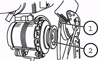
Operation 23. Cleaning the generator
Clean generator off dust and dirt. Check and, if necessary, tighten generator fixing bolts (1). Check condition and torque of generator terminal connections (2).


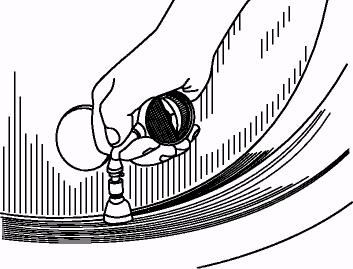
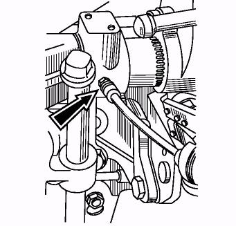
Operation 24. Draining sediment from fine fuel filter.
Drain sediment after every 250 operating hours. Turn off drain plug (1) at the bottom of the fine fuel filter by 2…3 turns according to the figure and drain sediment until pure fuel appears. Turn the plug forward.
Fuel input Fuel output
Operation 25. Oil level in transmission
Check oil level by oil-level gauge (1) on the left side of gear box casing. Normal oil level should be between the upper and lower mark of the oil gage.
NOTE: If your tractor is equipped with reducing gear, check oil level by level check plug, placed on the right side of the gear box. Normal oil level should be at the lower edge of the plug tread hole (2).
If it is necessary to correct oil level, take off the plug (3) of the upper cover of gear box and fill oil up to the required level.


Operation 26. Oil level in FDA casing.
FDA with bevel gear speed reducers
Check oil level in: 1. casings of wheel reduction gears (1) (of lower coned pairs); 2. casing of main gear (of front differential); 3. intermediate bearing of cardan shaft drive; 4. casings of upper coned pairs.
Oil level should reach lower edges of treaded check holes (1). If it is necessary, fill oil up to the required level through check holes.
Operation 27. Maintenance of steering gear drive
Maintenance of steering gear drive consists in periodic inspection of screw joint torquing. For minimal vibration level of steering wheel adjust steering column in the following way: • Take off cover 5; • Unscrew clamp 4 and remove the steering wheel 6; • Loosen nut 3; • Screw up a nut 2 till the contact with bush 1 so as to take up the clearances in connections; • Unscrew nut 2 by 1.5 turns and locknut with safety nut 3. • Install steering wheel 6, adjust high position and tighten clamp 4.

Operation 28. Rinse oil drain filter of steering booster.
For rinse of oil filter do the following:
а) remove facing; b) loose oil pipes 7, 13 и 15, unscrew bolts 5 from the cover 6 fastener group to the casing, using two extracting bolts take off the cover; c) screw out reducing valve 11 and take off drain filter 9; d) Rinse filter in wash liquid; e) Tighten up nut 8 of the turning shaft; f) Put filter in place and make assembly of the filter in the reverse order; g) simultaneously adjust axial play of the steering shaft, for this purpose do the following: loosen locknut 1 and screw down adjusting bolt 2 up to the stop into the shaft end, then unscrew by 1/8-1/10 turns and locknut with safety nut 1.
Operation 29. Lubricating of front axle stubs (Belarus 90)
Using grease gun make 10…12 injections of lubrication grease via compression cups (one cup for each stub). Grease is “LITOL-24”.

Maintenance No.3 (M-3) after every 1000 hours of operation
Perform operations of the previous maintenance plus the following operations:
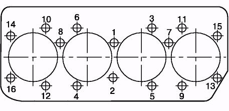
Operation 30. Tightening torque of cylinder head bolts
NOTE! Perform this operation only on heated engine.
Remove rockers’ cover, cover of cylinder head and rockers’ axle in assembly. Using torque wrench, check and tighten cylinder head bolts in sequence shown in the figure to the right. Bolts’ torque should be within 160... 180 N•m (16... 18 kgf•m).
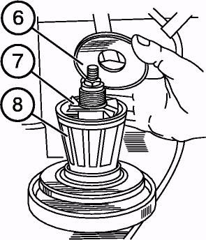
Operation 31. Engine coarse fuel filter
Wash fuel coarse filter by performing the following operations: • Shut off fuel tank cock. • Unscrew cup (3) fastening bolts (1) and pull out the cup. • Unscrew reflector with mesh (2) and take off scatterer . • Wash reflector with mesh, scatterer and filter cup in diesel fuel. • Assembly filter parts in reverse order. • Fill the system with fuel.
Bleed the system and remove air from the fuel system, as shown below (operation 40).
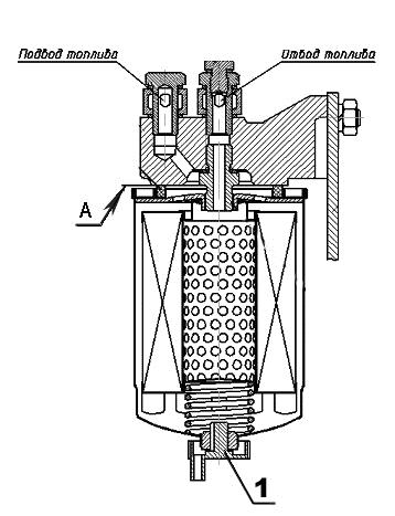
Operation 32. Changing filtering element of fine fuel filter
• Life time of the filter depend on purity of the used fuel. • Change filter according to the figure.
As follows: • - drain fuel from the filter by loosing of the plug at the bottom 4 of the filter casing.
•
Do not let fuel spillage, drain fuel only in reservoir.
• - unscrew filter 1 from union 8 in casing 2 and install instead of it a new filter, which is delivered in assembly with gasket 7, that should be previously lubricated with motor oil; • - after gasket (7) touches mounting pad A on the casing 2 screw filter up by ¾ turns. Install filter only by hand effort; • - open valve of the fuel tank and fill system with fuel.
Fuel input Fuel output 1 – filter FТ020-1117010; 2 – casing; 3 – arm; 4 - plug (for drain of sediment); 5outlet union; 6 –plug (for air input); 7 – gasket; 8 – union.

• To remove air from the system: • To remove air from the system, loosen the plug 6, situated on the tension bolt of the outlet union, by 2..3 turns.
Bleed system using manual purge pump 3, screw up plug by appearing of fuel without air bulbs. • Loosen plug 2 on the fuel pump casing. Bleed the system using priming pump until pure fuel without air bulbs appears, at the same time screw up plug 2. • Instead of fuel filter FТ020-1117010 one may install other indecomposable fuel filters having following technical parameters and sizes: • Sifting completeness at least 90%; • Nominal capacity at pressure difference of 0,01 MPa at least 150 liters per hour; • diameter - 95…105 mm; • height – 140…160 mm; • screw tread - М16x1,5; • outside diameter of sealing gasket - 70…75 mm.

Operation 33. Generator
Take drive belt (1) off generator pulley (2). Check rotation of generator rotor and plays in bearings. If there are any plays or rotor stickings, remove generator and send to workshop for repairs.
Operation 34. Steering joints
With engine running, rotate steering wheel to both sides to check free travel and plays of joints (1) of steering tie-rod (4). If joints have play, perform the following operations: • Take off locking wire (3). • Screw up threaded plug (2). • Locknut the plugs with wire (3).
NOTE: If play can not be eliminated by screwing up threaded plugs, disassembly the joint and replace worn out parts.
'Operation 35. Lubrication of RHA right brace bearing.
Using a grease gun lubricate the adjusting gear of right brace via compression cup (one point of greasing). Make 4…6 injections with the grease gun. Grease is “LITOL-24”.
'Operation 36. Lubrication of RHA turning shaft sleeves
Inject two lubrication points via compression cups in hitch attachment bracket until grease will come through splits. Grease is “LITOL-24”.
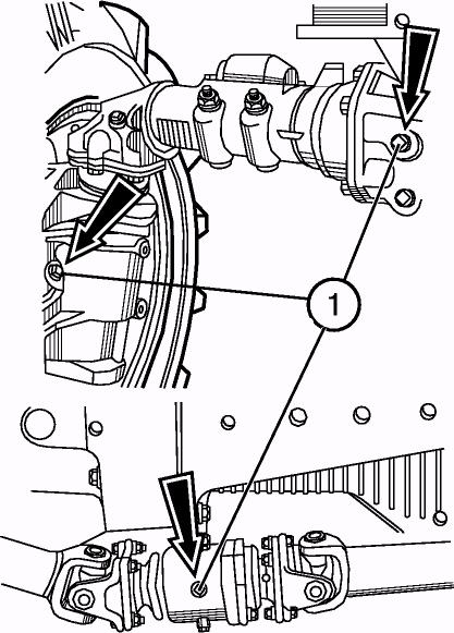
Operation 37. Outside bolted connections
Check and, if necessary, tighten most critical bolted connections: • Nuts of front and rear wheels, bolts of rear wheels’ hubs; • Front beam – half-frame girders; • Half-frame girders- clutch casing; • Fittings of TSU plates; • Engine – clutch casing; • Clutch casing – gear box casing; Gear box casing – rear axle housing;
Rear axle housing – RHA and TSU brackets; Front and rear cabin supports;
Arms and pins of hydraulic steering cylinder; Rear axle housing – sleeves of halfaxles; FDA casing – sleeves – wheel reduction gears;

Nuts of cardan shaft flanges; nuts of FDA body wedges; intermediate bearings casing of cardan drive – clutch casing; bracket fittings of lifting TSU and hydraulic hoist.
Operation 38. Changing oil in hydraulic system
• Before changing oil warm it up in hydraulic system. • Put the tractor on the even terrain, lower an implement and shut diesel down. • Engage brakes and shut diesel engine down. • Remove fill and drain plugs (1) from hydraulic tank and drain oil in special reservoir for used oil. ATTENTION! Be careful and avoid contact with hot oil. Properly dispose used oil.
• Put drain plugs (1) in place and fill pure oil in system. Put fill plug in its place.
Operation 39. Changing oil in transmission
• Before changing oil warm up the transmission. • Put the tractor on the even terrain, lower an implement and shut diesel down. • Engage parking brake and lock wheels using wedges. • Remove level check plug (2) and drain plugs (1) of rear axle and gear box casings and drain oil into special reservoir for used oil. Properly dispose used oil.
ATTENTION: Be careful and avoid contact with hot oil. • Fill pure oil in transmission. Put level check plug in its place (2).

Operation 40. Changing oil in FDA and intermediate bearing casings.
FDA with bevel gear speed reducers
• Before oil changing warm it up in FDA casings. • Put the tractor on the even terrain. Engage parking brake and lock rear wheels fore and aft using wedges. • Remove lever check/fill plugs (1) and drain plugs (2, 3, 4) from the casings of wheel reducing gears, main gear and intermediate bearing correspondingly. Drain oil into special reservoir.
ATTENTION: Be careful and avoid contact with hot oil. Properly dispose the oil. • Put in place and tighten fill plugs. • Fill casings up with fresh transmission oil Tap -15V, Tsp15K, TAD-17 or with their analogues up the lower edges of filling opening. To drain oil from the casing of upper bevel gear and pinion: - Using lubrication gun (3) for liquid lubrication pump out part of oil via filling opening (4); - Unscrew bolts (2), take off cover (1) and remove remaining oil; - Reinstall cover (1) and bolt (2); - Using lubrication gun for liquid lubrication fill the capacities of upper bevel gears and pinions with oil up to lower edge of opening (4); - Put in place and tighten level check/fill plugs.


Operating 41. Engine oil pre-filter
Loosen four clamps of connecting sleeves and remove filter from oil conduit, under engine oil radiator.
IMPOTANT! Make notice of how filter was placed in oil conduit. Random filter installation is not allowed.
Wash filter in diesel fuel and blow off with compressed air in the direction of arrow imprinted on the filter housing.
Mount the filter, paying attention to its correct orientation in the oil conduit.
Tighten clamps of sleeves.
Operation 42. Washing engine breathers
• Unscrew bolts (1) and remove breather body (2). • Pull the breather out of the body, wash with diesel fuel and blow off with compressed air. Pour some motor oil inside breather filter, and giving some time to drain it, put in its place.
Operation 43. Adjustments of steering booster
In hydraulic booster following elements are regulated: coupling engagement “worm and sector”, engagement “sector and rack”, tightening of the worm nut, axial stroke of turning shaft, emergency valve and also valve control of differential blocking.
1 – spherical nut; 2 – washer; 3 – slide; 4 – mounting washers; 5 – bolts.
For adjustment of engagement “worm – sector” loosen bolt 5, and input key in hub flange recess, turn hub 6 clockwise (along the tractor movement) as far as it will go, at this moment tie-rod arm should be in middle position, then turn hub contra clockwise by 10-12 mm to outside diameter of the flange. Tighten bolt 5, crank up the engine and make sure, that there are no jamming, when rotate steering wheel to both sides against to the stop. If it is necessary, increase clearance in engagement by turning hub contra clockwise until jamming disappears. For adjustment of engagement “sector- rack” reduce thickness of shim washer set 24 under the flange of limit stop 23 until between stop and rack appears 0,1 – 0,3 mm clearance. By clearance control press rack to the sector. Using spherical worm nut 30 can be tightened end-thrust bearings 28. Correct tightening of end-thrust bearings is the most important factor for normal operation of hydraulic booster. Excessive nut tightening can cause warp of valve core and nonuniform turn effort. Before tightening nuts, bolt on distribution block, but previously shim washers under bolt heads in thickness of head flange (Fig. 117). Tighten worm nut to 2 kgf•m (20 N-m), unscrew it by 1/12— 1/10 turns until the hole in the worm matches locknut pin hole and then fasten nut by cotter. Unscrew two tension bolts from distributor block to the casing, put cover and fix reliably distributor block. For adjustment of axial stroke of turning shaft 21 loosen check nut 12, screw adjusting bolt 10 against the stop into the shaft end, then unscrew by 1/8 — 1/10 turns and locknut with safety nut. For adjusting of emergency valve attach to discharge manifold or to valve cover instead of plug 1 manometer with gauge face not less than 100kgf/cm2 (10 МPа). Turn steering wheel against the stop, let diesel operate at maximal speed and turn regulating screw 3 until manometer indicate pressure 88 kgf/sm2 (8.8 МPа). After valve adjusting locknut the cap with wire. Perform adjustment at the oil temperature 50±5°С. Check free travel of the steering wheel, when diesel is in operation on tractor parking. Free travel in this case should not exceed 20°. At increased free travel check plays in steering gear connections, screw nuts of tie-rod arm, of sector and pivoted levers, adjust joints of steering link, check tightening of the worm nut, of engagements “worm- sector”, “sector – rack” and axial stroke of hydraulic booster turning shaft.
Special maintenance After every 2000 hours of operation
Operation 44. Checking engine nozzles
IMPOTANT! Nozzles should be cleaned and adjusted in specialized workshop of the dealer.
WARNING: Diesel fuel is sprayed under high pressure and can cause serious trauma if nozzle spraying is checked by hand. Use for this purpose paper or carton. Wear protective glasses. Before connecting or disconnecting of fuel lines shut down diesel for pressure relief. Before diesel start tighten all connections of fuel lines. By hand skin contact with fuel immediately apply to the medical assistance, otherwise blood poisoning is possible.
NOTE: It is convenient to have spare set of nozzles, checked and adjusted to be quickly installed on the engine.
Take off and replace nozzles, having performed the following operations: • Before disconnecting or loosening of any parts of the fuel system, thoroughly clean adjacent operation surface. • Unscrew nuts (4) and disconnect high-pressure fuel lines (5) from nozzles (3) and fuel pump. • Take off fuel lines (5). • Unscrew four bolts (1) of the drain duct and take off drain fuel line (2). Sort out sealing copper washers (two washer per each “banjo” bolt). Unscrew nozzles fixing bolts (6) and take off nozzles (3). • Send nozzles to dealer’s workshop for servicing. • Put checked, cleaned and adjusted nozzles in the reverse order. • Bleed the system.
IMPOTANT! Use new copper washers during each mounting of nozzles.

Operation 45. Advance angle of
fuel injection
Adjusting advance angle of fuel pump injection should be within 19° - 21° till UDC (D-243).
Advance angle should be checked and adjusted in specialized workshop of the dealer.
IMPOTANT! Adjustment of fuel equipment by tractor operator (owner) is considered as grounds for cancellation of manufacturer’s warranty obligations. • Check if radiator core is clean. If necessary, wash the radiator and blow off the core with compressed air (blowing direction – from the engine side).
ATTENTION! Radiator clogging, insufficient tension of the fan belt, contamination inside cooling system may lead to engine overheating and failure.
Operation 46. Adjusting of the fuel pump on stand
Fuel pump should be adjusted by dealer in specialized workshop using special equipment.
Operation 47. Washing engine cooling system.
To wash the system use solution of 50-60 grams of soda ash per one liter of water. Observe the following order of washing:
• Fill radiator with two liters of kerosene and fill the system with prepared solution; • Start the engine and let it operate for 8-10 hours, then drain solution and rinse the cooling system with pure water;


