5 minute read
2.2 Removing and installing catalytic converter


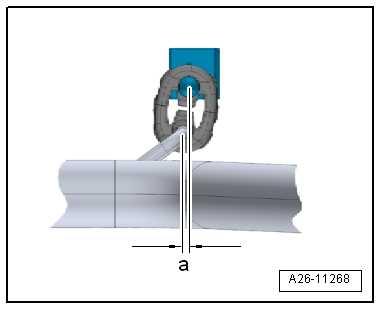
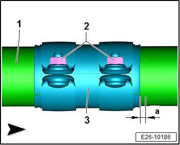
– Slacken nuts on front clamp -arrows-.
– Push exhaust system towards front until preloading at mount‐ing for exhaust pipe -a- = 5 mm. – Fit front clamp ⇒ “1.6 Installation position of clamp”, page 453 . Specified torques ♦ Clamp ⇒ page 454
Protected by copyright. Copying for private or commercial purposes, in part or in whole, is not permitted unless authorised by SEAT S.A. SEAT S.A does not guarantee or accept any liability with respect to the correctness of information in this document. Copyright by SEAT S.A.

1.5 Checking exhaust system for leaks
Procedure
– Start engine, and run at idling speed. – Seal exhaust pipes with cloths or plugs, for example, for the duration of the leakage test. – Check (by listening) points of connection between exhaust manifold and the cylinder head, between turbocharger and front exhaust pipe etc. to make sure there are no leaks. – Repair any leaks found.
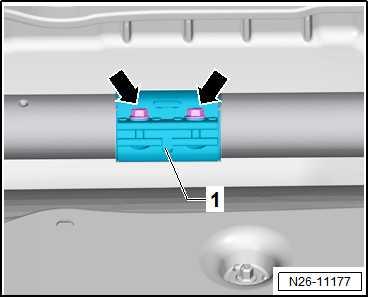
1.6 Installation position of clamp
Note
Make sure to use clamps with continuous clip only.
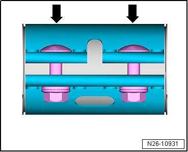
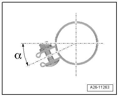
Position of clamp Make sure that installation dimension -a- is obtained.
a - Distance to marking: approx. 8.5 mm 1 - Clamp 2 - Front exhaust pipe 3 - Securing nut Installation position of the clamping sleeve
• Angle -α- (= approx. 20°) must not be exceeded.
Specified torques
Component
Clamp Specified torque
30 Nm
1.7 Align end exhaust pipes
Procedure
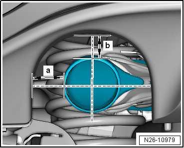
– Unfasten rear silencer mounting to align tailpipes. – Align rear silencer maintaining distance -a- and -b- between bumper cut-out and exhaust pipe. Adjustment dimensions Dimension a: 25 mm
Dimension b: 30 mm
Specified torques ♦ Securing bolts for mountings ⇒ “1.1 Assembly overview - silencers”, page 435 ♦ Clamp ⇒ page 454
Protected by copyright. Copying for private or commercial purposes, in part or in whole, is not permitted unless authorised by SEAT S.A. SEAT S.A does not guarantee or accept any liability with respect to the correctness of information in this document. Copyright by SEAT S.A.
2 Exhaust gas cleaning
⇒ “2.1 Assembly overview - emission control”, page 455 ⇒ “2.2 Removing and installing catalytic converter”, page 459 ⇒ “2.3 Removing and installing particulate filter”, page 463
2.1 Assembly overview - emission control
⇒ “2.1.1 Assembly overview - emission control, Ateca, Leon 2013, Ibiza 2018, Arona”, page 455 ⇒ “2.1.2 Assembly overview - emission control, Toledo 2013, Ibi‐za 2016”, page 458
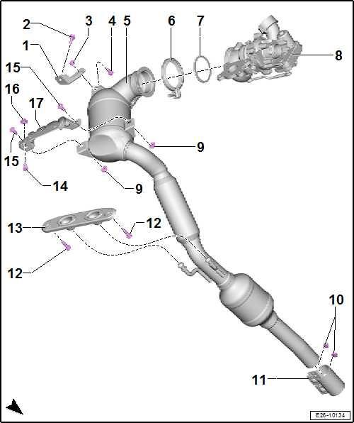
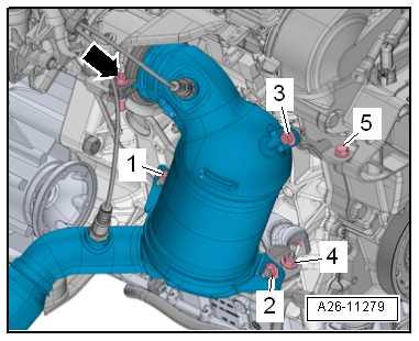
1 - Support 2 - Bolt ❑ Specified torque and tightening sequence ⇒ page 456 3 - Nut ❑ Specified torque and tightening sequence ⇒ page 456 4 - Bolt Protected by copyright. Copying for private or commercial purposes, in part or in whole, is not ❑ Specified torque and tightening sequence permitted unless authorised by SEAT S.A. SEAT S.A does not guarantee or accept any liability with respect to the correctness of information in this document. Copyright by SEAT S.A. ⇒ page 456 5 - Front exhaust pipe with cat‐alytic converter ❑ Do not allow the decou‐pling element to kink by more than 10°. It could become damaged. ❑ Install decoupling ele‐ment so that it is not un‐der tension. ❑ Take care not to dam‐age wire mesh on de‐coupling element. ❑ Protect catalytic con‐verter from damage by knocks and impact ❑ Removing and installing ⇒ “2.2.1 Catalytic con‐verter - removing and in‐stalling, Leon 2013, Ibi‐za 2018, Arona”, page 459 ❑ Do not remove protec‐tive packaging from replacement part until you are ready to fit the flexible joint ❑ Aligning exhaust system free of stress ⇒ “1.4 Aligning exhaust system free of stress”, page 452 6 - Screw-type clip ❑ Renew after removal ❑ Specified torque and tightening sequence ⇒ page 456
7 - Seal ❑ Renew after removal
8 - Turbocharger ❑ Removing and installing ⇒ “1.2 Removing and installing turbocharger”, page 353 ❑ Specified torque and tightening sequence ⇒ “1.1 Assembly overview - turbocharger”, page 351 9 - Nut ❑ Specified torque and tightening sequence ⇒ page 456 10 - Nut ❑ 25 Nm
11 - Front clamp ❑ Align exhaust system free of stress before tightening clamp ⇒ “1.4 Aligning exhaust system free of stress”, page 452 ❑ Fitting position ⇒ “1.6 Installation position of clamp”, page 453 ❑ Tighten threaded connections evenly. 12 - Bolt ❑ 20 Nm
13 - Mounting ❑ Renew if damaged Protected by copyright. Copying for private or commercial purposes, in part or in whole, is not permitted unless authorised by SEAT S.A. SEAT S.A does not guarantee or accept any liability with 14 - Bolt respect to the correctness of information in this document. Copyright by SEAT S.A. ❑ Specified torque and tightening sequence ⇒ page 456 15 - Bolt ❑ Specified torque and tightening sequence ⇒ page 456 16 - Nut ❑ Specified torque and tightening sequence ⇒ page 456 17 - Support
Installing catalytic converter - specified torque and tightening se‐quence
1. – Fit catalytic converter to tur‐bocharger, attach screw-type clip -arrow- without tightening 2. – Loosely screw in bolts -3, 5and bolts -1, 2, 4- by hand • It should still be possible to move catalytic converter and bracket.
3. – Tighten screw-type clip -arrow-.
4. – Tighten bolts and nuts in the sequence -1 to 5-. 15 Nm
20 Nm
Bracket and heat shields