4 minute read
8.2 Removing and installing lambda probe


7 High-pressure pump
⇒ “7.1 Assembly overview - high-pressure pump”, page 425 ⇒ “7.2 Removing and installing high-pressure pump”, page 426 ⇒ “7.3 Removing and installing high-pressure pipe”, page 427
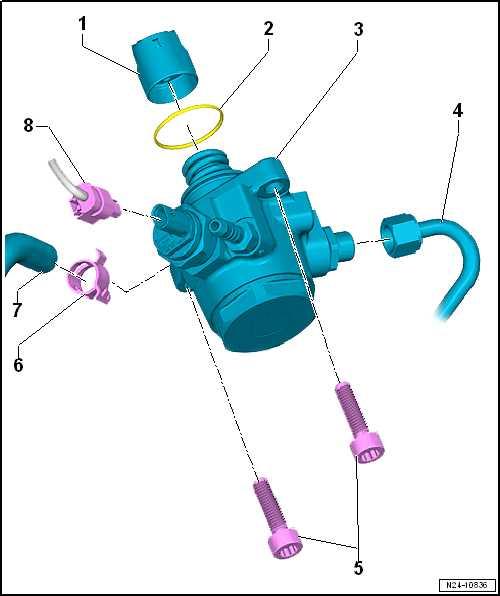
7.1 Assembly overview - high-pressure pump
1 - Roller tappet ❑ When installing lubri‐cate lightly with clean engine oil 2 - O-ring ❑ Renew after removal ❑ When installing lubri‐cate lightly with clean engine oil 3 - High-pressure pump ❑ With fuel pressure regu‐lating valve - N276- . ❑ Do not dismantle. ❑ Removing and installing ⇒ page 426 4 - High-pressure pipe ❑ Removing and installing ⇒ page 427 ❑ Renew after removal ❑ Check for damage be‐fore reinstalling. ❑ Do not alter shape. ❑ Unions must be free of damage
Protected by copyright. Copying for private or commercial purposes, in part or in whole, is not ❑ Lubricate thread of un‐permitted unless authorised by SEAT S.A. SEAT S.A does not guarantee or accept any liability with respect to the correctness of information in this document. Copyright by SEAT S.A. ion nuts with clean en‐gine oil ❑ 16 Nm + 45°
5 - Bolt ❑ Renew after removal ❑ Specified torque and tightening sequence ⇒ page 426 6 - Hose clamp 7 - Return (leakage) line (fuel return line) 8 - Electrical connector

High-pressure pump - specified torque and tightening sequence
Note
If a further tightening angle is specified for certain bolts, these must be renewed.
Install high-pressure pump as follows to avoid deformation of the high-pressure pump flange: – Tighten bolts in stages as follows:
Stage Bolts Specified torque/turning further angle 1. -1, 4- Screw in by hand as far as stop 2. -1, 4- Tighten one turn alternately until flange of high-pressure pump makes contact with camshaft housing
3. -1, 4- 20 Nm
4. -1, 4- Turn 90° further

Protected by copyright. Copying for private or commercial purposes, in part or in whole, is not permitted unless authorised by SEAT S.A. SEAT S.A does not guarantee or accept any liability with respect to the correctness of information in this document. Copyright by SEAT S.A.7.2 Removing and installing high-pressure pump
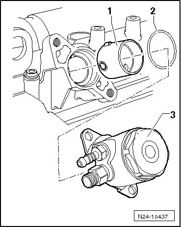
Removing • Engine cold. – Remove air filter housing ⇒ “3.2 Removing and installing air filter housing”, page 397 . – Remove high-pressure pipe ⇒ “7.3 Removing and installing high-pressure pipe”, page 427 . – Disconnect connector -3-.
Note
Place a cloth underneath to catch escaping fuel.
– Release hose clip -2- and detach fuel supply hose. – Unscrew bolts -1 and 4-, and remove high-pressure pump with roller tappet.
Installing – Check roller tappet for damage and renew if necessary. – Moisten roller tappet -1- with clean engine oil. – Insert oiled roller tappet -1- into camshaft housing. – Turn crankshaft in direction of engine rotation until roller tappet is at bottom dead centre.
Note
Renew O-ring.
– Insert new, lubricated O-ring -2- in groove of high-pressure pump -3-.
Note
If the high-pressure pump is tightened unevenly (i.e canted), it may become damaged.
– Fit high-pressure pump, and initially and alternately handtighten bolts -1 and 4-.
– Tighten bolts -1 and 4- to final specified torque ⇒ page 426 . – Push on fuel hose, and secure it with hose clip -2-. – Push on connector -3-.
– Install high-pressure pipe ⇒ “7.3 Removing and installing high-pressure pipe”, page 427 . – Install air filter housing ⇒ “3.2 Removing and installing air filter housing”, page 397 . – Check fuel system for leaks. Specified torques ♦ ⇒ “2.1 Assembly overview - fuel rail with injectors”, page 383 ♦ ⇒ “7.1 Assembly overview - high-pressure pump”, page 425 ♦ ⇒ “3.1 Assembly overview - air filter housing”, page 393
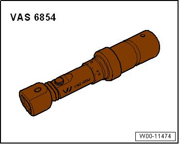
7.3 Removing and installing high-pressure Protected by copyright. Copying for private or commercial purposes, in part or in whole, is not pipe permitted unless authorised by SEAT S.A. SEAT S.A does not guarantee or accept any liability with respect to the correctness of information in this document. Copyright by SEAT S.A.Special tools and workshop equipment required ♦ Torque wrench - VAS 6854-
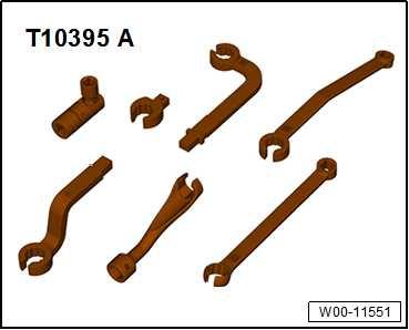
♦ Tool set - T10395A-
Removing – Remove air filter housing ⇒ “3.2 Removing and installing air filter housing”, page 397 .
CAUTION
The fuel system is pressurised. Danger of injury caused by fuel spray. – Wear protective goggles. – Wear protective gloves. – To release pressure, wrap a clean cloth around the connec‐tion and carefully loosen the connection.
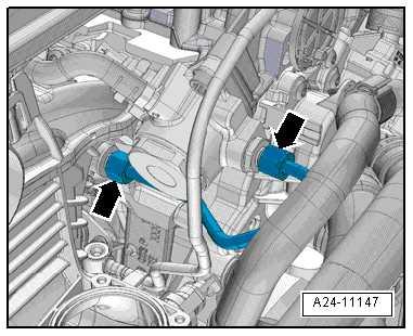
– Unscrew union nuts -arrows- and detach high-pressure pipe. Installing Install in reverse order of removal, observing the following: – Lubricate thread of union nuts with clean engine oil. – Hand-tighten union nuts for high-pressure pipe (make sure that pipe is not under stress). – Tighten union nuts using torque wrench - VAS 6854- and tool attachment - T10395/3- .
Specified torques ♦ ⇒ “7.1 Assembly overview - high-pressure pump”, page 425 ♦ ⇒ “2.1 Assembly overview - fuel rail with injectors”, page 383
Protected by copyright. Copying for private or commercial purposes, in part or in whole, is not permitted unless authorised by SEAT S.A. SEAT S.A does not guarantee or accept any liability with respect to the correctness of information in this document. Copyright by SEAT S.A.


