
6 minute read
2.3 Removing and installing injectors


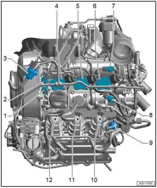
1 - Inlet camshaft control valve 1 - N205❑ Assembly overview ⇒ “3.1 Assembly over‐view - valve gear”, page 204
2 - Exhaust camshaft control valve 1 - N318❑ Assembly overview ⇒ “3.1 Assembly over‐view - valve gear”, page 204
3 - Activated charcoal filter sol‐enoid valve 1 - N80-
4 - Ignition coil 1 with output stage - N70❑ Assembly overview ⇒ “1.1 Assembly over‐view - ignition system”, page 464 5 - Ignition coil 2 with output stage - N127❑ Assembly overview ⇒ “1.1 Assembly over‐view - ignition system”, page 464 6 - Ignition coil 3 with output stage - N291❑ Assembly overview ⇒ “1.1 Assembly over‐view - ignition system”, page 464 7 - Hall sender 3 - G163❑ Assembly overview ⇒ “1.1 Assembly over‐view - ignition system”, page 464 8 - Hall sender - G40- (camshaft position sensor) ❑ Assembly overview ⇒ “1.1 Assembly overview - ignition system”, page 464 9 - Fuel metering valve - N290❑ Assembly overview Protected by copyright. Copying for private or commercial purposes, in part or in whole, is not⇒ “7.1 Assembly overview - high-pressure pump”, page 425 10 - Injector, cylinder 3 - N32- permitted unless authorised by SEAT S.A. SEAT S.A does not guarantee or accept any liability with respect to the correctness of information in this document. Copyright by SEAT S.A. ❑ Assembly overview ⇒ “2.1 Assembly overview - fuel rail with injectors”, page 383 11 - Injector, cylinder 2 - N31❑ Assembly overview ⇒ “2.1 Assembly overview - fuel rail with injectors”, page 383 12 - Injector, cylinder 1 - N30❑ Assembly overview ⇒ “2.1 Assembly overview - fuel rail with injectors”, page 383
1 - Oil pressure sender - G10❑ Assembly overview ⇒ “4.1 Assembly over‐view - oil filter, oil pres‐sure switch”, page 251 2 - Fuel pressure sender G247❑ Assembly overview ⇒ “2.1 Assembly over‐view - fuel rail with injec‐tors”, page 383 3 - Throttle valve module GX3❑ Consisting of: Throttle valve module J338-
Throttle valve drive (elec‐tric power control) G186-
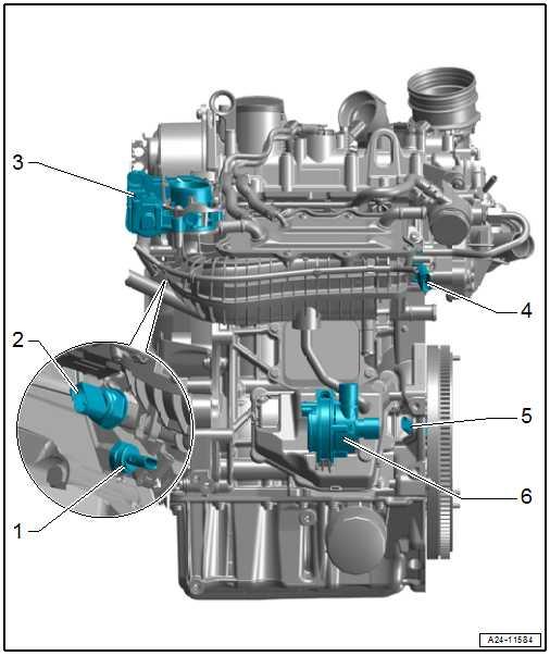
Angle sender for throttle valve drive - G187-
Throttle valve drive angle sender 2 (electric power control) - G188❑ Protected by copyright. Copying for private or commercial purposes, in part or in whole, is not permitted unless authorised by SEAT S.A. SEAT S.A does not guarantee or accept any liability with respect to the correctness of information in this document. Copyright by SEAT S.A. Removing and installing ⇒ “4.3 Removing and in‐stalling throttle valve module GX3 ”, page 402 ❑ Cleaning ⇒ “4.4 Cleaning throttle valve module GX3 ”, page 403 ❑ Assembly overview ⇒ “4.1 Assembly overview - intake manifold”, page 399 4 - Intake manifold sender - GX9❑ Consisting of: Intake manifold pressure sender - G71-
Intake manifold temperature sender - G72❑ Assembly overview ⇒ “4.1 Assembly overview - intake manifold”, page 399 5 - Engine speed sender - G28❑ Assembly overview ⇒ “1.1 Assembly overview - ignition system”, page 464 6 - Continued coolant circulation pump - V51❑ Assembly overview ⇒ “2.2 Assembly overview - electric coolant pump”, page 280
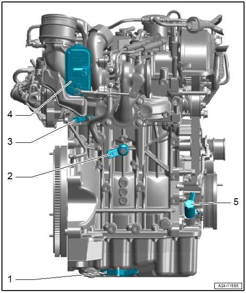
1 - Oil level and oil temperature sender - G266❑ Assembly overview ⇒ “1.1 Assembly over‐view - sump/oil pump”, page 233 2 - Knock sensor 1 - G61❑ Assembly overview ⇒ “1.1 Assembly over‐view - ignition system”, page 464 3 - Coolant temperature send‐er - G62❑ Assembly overview ⇒ “2.3 Assembly over‐view - coolant tempera‐ture sender”, page 282 4 - Charge pressure positioner - V465❑ Assembly overview ⇒ “1.1 Assembly over‐view - turbocharger”, page 351 5 - Valve for oil pressure con‐trol - N428❑ Assembly overview ⇒ page 251
Protected by copyright. Copying for private or commercial purposes, in part or in whole, is not permitted unless authorised by SEAT S.A. SEAT S.A does not guarantee or accept any liability with respect to the correctness of information in this document. Copyright by SEAT S.A.
2 Injectors
⇒ “2.1 Assembly overview - fuel rail with injectors”, page 383 ⇒ “2.2 Removing and installing fuel rail”, page 385 ⇒ “2.3 Removing and installing injectors”, page 386 ⇒ “2.4 Cleaning injectors”, page 391
2.1 Assembly overview - fuel rail with injec‐tors
⇒ “2.1.1 Assembly overview - fuel rail with injectors, Version 1”, page 383 ⇒ “2.1.2 Assembly overview - fuel rail with injectors, Version 2”, page 384
1 - Fuel distributor ❑ Removing and installing ⇒ “2.2 Removing and in‐stalling fuel rail”, page 385 2 - Bolt ❑ Renew after removal ❑ Tighten alternately in stages; final torque 9 Nm ❑ 2 off ❑ M6x55
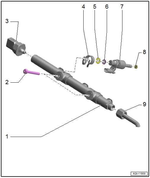
3 - Fuel pressure sender G247❑ Checking ⇒ “5.2 Checking fuel pressure sender G247 ”, page 406 ❑ Removing and installing ⇒ “5.1 Removing and in‐Protected by copyright. Copying for private or commercial purposes, in part or in whole, is notstalling fuel pressure permitted unless authorised by SEAT S.A. SEAT S.A does not guarantee or accept any liability withsender G247 ”, page 405 respect to the correctness of information in this document. Copyright by SEAT S.A. ❑ Lubricate taper lightly with clean engine oil; do not lubricate thread ❑ 22 Nm
4 - Support ring ❑ Renew after removal ❑ Fuel rail exerts force which secures injector in cylinder head via this support ring ❑ Clipped to -item 75 - O-ring ❑ Renew after removal ❑ Lubricate with clean engine oil.
6 - Spacer ring ❑ Renew if damaged 7 - Injector ❑ Removing and installing ⇒ “2.3 Removing and installing injectors”, page 386 8 - Combustion chamber seal ❑ Do not treat with grease or other lubricant. ❑ Renewing ⇒ “2.3 Removing and installing injectors”, page 386 9 - High-pressure pipe ❑ Renew after removal ❑ Unions must be free of damage ❑ Do not alter shape. ❑ Removing and installing ⇒ “7.3 Removing and installing high-pressure pipe”, page 427 ❑ Lubricate thread of union nuts with clean engine oil ❑ 16 Nm + 45°
1 - Fuel distributor ❑ Removing and installing ⇒ “2.2 Removing and in‐stalling fuel rail”, page 385 2 - Bolt ❑ Renew after removal ❑ Tighten alternately in stages; final torque 9 Nm ❑ 2 off ❑ M6x30
3 - Fuel pressure sender G247❑ Checking ⇒ “5.2 Checking fuel pressure sender G247 ”, page 406 ❑ Removing and installing ⇒ “5.1 Removing and in‐stalling fuel pressure sender G247 ”, page 405 ❑ Lubricate taper lightly with clean engine oil; do not lubricate thread ❑ 22 Nm

4 - Support ring ❑ Renew after removal
Protected by copyright. Copying for private or commercial purposes, in part or in whole, is not permitted unless authorised by SEAT S.A. SEAT S.A does not guarantee or accept any liability with respect to the correctness of information in this document. Copyright by SEAT S.A. ❑ Fuel rail exerts force which secures injector in cylinder head via this support ring ❑ Clipped to -item 7-


