4 minute read
1.2 Checking cooling system for leaks


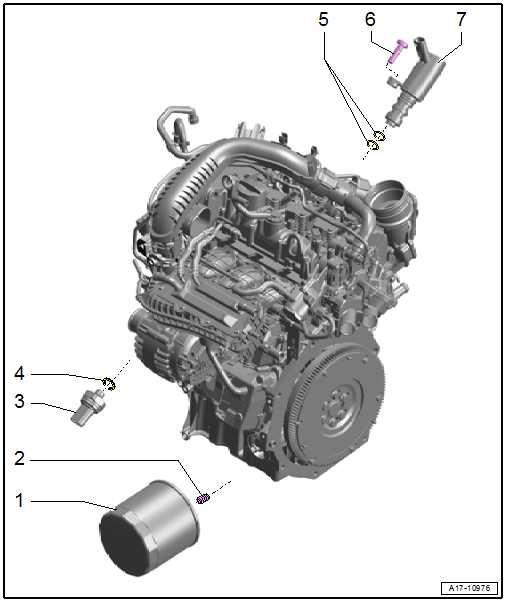
4 Oil filter, oil pressure switch
⇒ “4.1 Assembly overview - oil filter, oil pressure switch”, page 251 ⇒ “4.2 Removing and installing oil pressure sender G10 ”, page 252 ⇒ “4.3 Checking oil pressure and oil pressure switch”, page 253 ⇒ “4.4 Removing and installing oil filter housing”, page 254 ⇒ “4.5 Removing and installing oil pressure regulating valve N428 ”, page 254
1 - Oil filter ❑ See note ⇒ “1.1 Assembly over‐view - sump/oil pump”, page 233 . ❑ Removing and installing ⇒ “4.4 Removing and in‐stalling oil filter hous‐ing”, page 254 ❑ Tighten loosened con‐necting union for oil filter ⇒ Fig. ““Tightening con‐necting union for oil fil‐ter”“ , page 236 2 - Threaded sleeve ❑ If connecting union for oil filter in sump became loose ⇒ page 252 Protected by copyright. Copying for private or commercial purposes, in part or in whole, is not permitted unless authorised by SEAT S.A. SEAT S.A does not guarantee or accept any liability with3 - Oil pressure sender - G10respect to the correctness of information in this document. Copyright by SEAT S.A.❑ Switch pressure 0.3 to 0.6 bar ❑ Insulation, black
❑ Check in Guided fault finding ⇒ Vehicle di‐agnostic tester ❑ Removing and installing ⇒ “4.2 Removing and in‐stalling oil pressure sender G10 ”, page 252 ❑ Renew after removal ❑ 10 Nm +45°

4 - Seal ❑ Renew after each re‐moval ⇒ Electronic Parts Catalogue 5 - O-rings ❑ No replacement part ❑ In case of leakage, renew valve ⇒ Item 7 (page 252) 6 - Bolt ❑ 8 Nm
7 - Valve for oil pressure control - N428❑ Removing and installing ⇒ “4.5 Removing and installing oil pressure regulating valve N428 ”, page 254 ❑ Renew valve for oil pressure control - N428- if there is swarf in the engine oil system ⇒ Electronic parts catalogue
Tightening connecting union for oil filter • If the connecting union -2- in the top section of sump -1- is loose, retighten it as described below. Use only the two nuts -3 and 4- for this procedure. • Hexagon nut , qty. 2, ⇒ Electronic Parts Catalogue – Screw nuts -3- and -4- onto connecting union -2-, and counter lock them.
– Tighten connecting union -2- via nut -3-. – Loosen the two nuts and remove them, taking care not to loosen the connecting union. Specified torque
Threaded sleeve
-2Specified torque
50 Nm
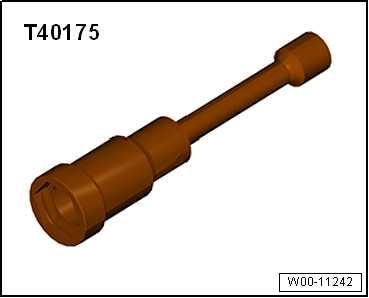
Special tools and workshop equipment required ♦ 24 mm jointed spanner - T40175-

Protected by copyright. Copying for private or commercial purposes, in part or in whole, is not permitted unless authorised by SEAT S.A. SEAT S.A does not guarantee or accept any liability with respect to the correctness of information in this document. Copyright by SEAT S.A.
Removing
Note
Attach all heat-shielding sleeves in the same places when instal‐ling.
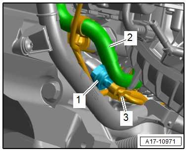
– Remove alternator ⇒ Electrical system; Rep. gr. 27 ; Alter‐nator; Removing and installing alternator . – Lay fuel hose -2- at intake manifold to one side. – Disconnect connector -3-.
– Place a cloth underneath to catch escaping engine oil. – Unscrew oil pressure sender - G10- -1- using U/J extension and socket, 24 mm - T40175- .
Installing Install in reverse order of removal, observing the following:
Note
Protected by copyright. Copying for private or commercial purposes, in part or in whole, is not permitted unless authorised by SEAT S.A. SEAT S.A does not guarantee or accept any liability with respect to the correctness of information in this document. Copyright by SEAT S.A.
♦ Always renew the seal of the oil pressure sender - G10- after disassembly.⇒ Electronic parts catalogue ♦ Insert the new oil pressure sender - G10- immediately in the bore to avoid loss of oil.
– Check oil level ⇒ “1.2 Engine oil:”, page 237 Specified torques ♦ Specified torque for oil pressure switch ⇒ “4.1 Assembly overview - oil filter, oil pressure switch”, page 251
♦ Securing bolts of alternator ⇒ Rep. gr. 27 ; Alternator; As‐sembly overview - alternator .
4.3 Checking oil pressure and oil pressure switch
Note
♦ The oil pressure sender - G10- is installed to the engine. ♦ The oil pressure sender - G10- can be diagnosed. ♦ The oil pressure sender is checked using the ⇒ Vehicle diag‐nostic tester.
♦ Any issues are stored in the event memory. ♦ The oil pressure sender is fitted with a captive seal. ♦ The seal is not designed for repeated use. The oil pressure sender must always be renewed after removing.
♦ Diagnostics
♦ 01 - Engine
♦ 0001 - Engine control unit
♦ 0001 - Electrical components


