22 minute read
1.3 Draining and adding coolant


♦ Oil pressure sensor G10
4.4 Removing and installing oil filter housing
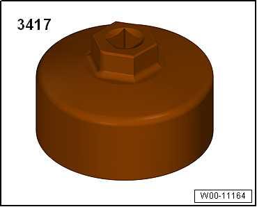
Special tools and workshop equipment required ♦ Oil filter tool - 3417-
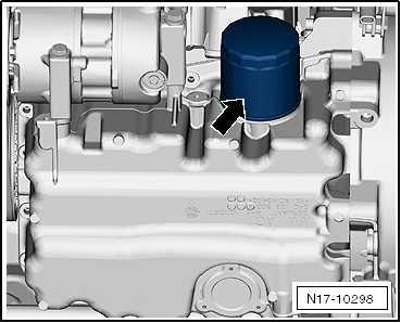
Removing – Drain engine oil ⇒ “1.2 Engine oil:”, page 237 . – Remove oil filter -arrow- with oil filter tool - 3417- .
Installing – Fill oil filter with engine oil and tighten it to specified torque using oil filter tool - 3417- ⇒ page 254 .
Note
Protected by copyright. Copying for private or commercial purposes, in part or in whole, is not permitted unless authorised by SEAT S.A. SEAT S.A does not guarantee or accept any liability with respect to the correctness of information in this document. Copyright by SEAT S.A.
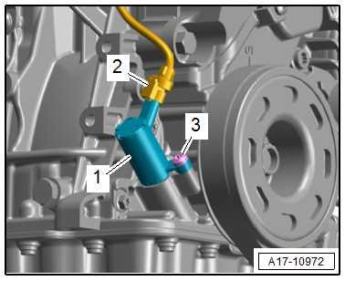
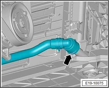
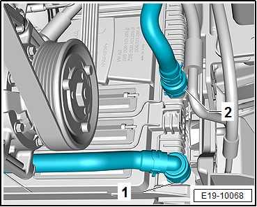
If connecting union -2- in sump -1- became loose, retighten it as described below ⇒ page 252

– Fill with engine oil and check oil level ⇒ “1.2 Engine oil:”, page 237 . Specified torque for oil filter

Component
Oil filter Specified torque Conditions
20 Nm Coat gasket with engine oil.
4.5 Removing and installing oil pressure regulating valve - N428-
Removing
Note
Attach all heat-shielding sleeves in the same places when instal‐ling.
– Detach heat insulation sleeves.
– Unplug electrical connector -2-.
Note
Place a cloth underneath to catch escaping engine oil.
– Unscrew bolt -3-, and pull off valve for oil pressure control N428- -1-.
Installing Install in reverse order of removal, observing the following:
Note
♦ In case of leaks, valve for oil pressure control - N428- must be renewed.
♦ Seals are not available separately.
Specified torques ♦ ⇒ “4.1 Assembly overview - oil filter, oil pressure switch”, page 251
♦ ⇒ “2.1 Assembly overview - emission control”, page 455
Protected by copyright. Copying for private or commercial purposes, in part or in whole, is not permitted unless authorised by SEAT S.A. SEAT S.A does not guarantee or accept any liability with respect to the correctness of information in this document. Copyright by SEAT S.A.
19 – Cooling
1 Cooling system/coolant
⇒ “1.1 Connection diagram - coolant hoses”, page 256 ⇒ “1.2 Checking cooling system for leaks”, page 257 ⇒ “1.3 Draining and adding coolant”, page 260
1.1 Connection diagram - coolant hoses
Note
♦ Blue = large coolant circuit. ♦ Red = small coolant circuit.
♦ Orange = Charge air cooling circuit. ♦ Brown = heater circuit.
♦ The arrows point in the direction of coolant flow.
1 - Radiator for charge air cool‐ing circuit 2 - Back-pressure valve 3 - Intercooler ❑ In the intake manifold
4 - Cylinder head and crank‐case
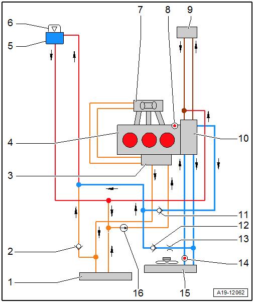
5 - Coolant expansion tank ❑ With filler cap 6 - Cap Protected by copyright. Copying for private or commercial purposes, in part or in whole, is not permitted unless authorised by SEAT S.A. SEAT S.A does not guarantee or accept any liability with respect to the correctness of information in this document. Copyright by SEAT S.A.❑ For coolant expansion tank ❑ Design may vary de‐pending on model year ❑ Check pressure relief valve ⇒ page 259 7 - Turbocharger 8 - Coolant temperature send‐er - G62-
9 - Heat exchanger for heater 10 - Coolant pump ❑ With thermostat hous‐ing
11 - Back-pressure valve 12 - Back-pressure valve 13 - Restrictor
14 - Radiator outlet coolant temperature sender - G8315 - Radiator for engine cool‐ant
16 - Continued coolant circulation pump - V51-
1.2 Checking cooling system for leaks
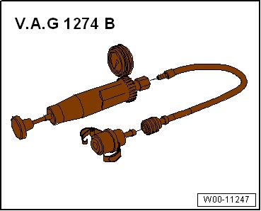
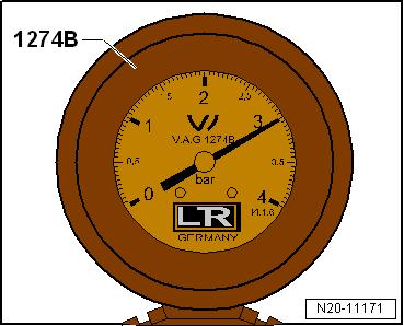
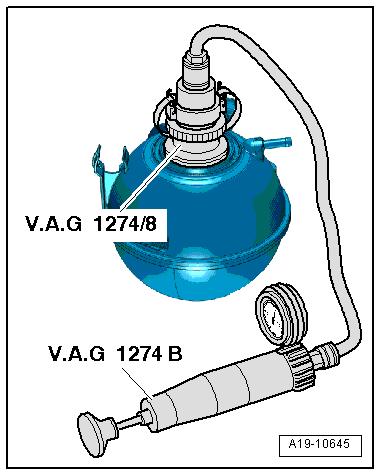
Special tools and workshop equipment required ♦ Cooling system tester - V.A.G 1274 B-
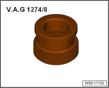
♦ Adapter for cooling system tester - V.A.G 1274/8-
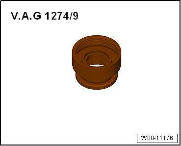
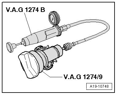
♦ Adapter for cooling system tester - V.A.G 1274/9-
Protected by copyright. Copying for private or commercial purposes, in part or in whole, is not permitted unless authorised by SEAT S.A. SEAT S.A does not guarantee or accept any liability with respect to the correctness of information in this document. Copyright by SEAT S.A.
Note
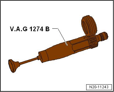
To perform the leakage test correctly, first run a self-test on the cooling system tester - V.A.G 1274 B- .
Self test of cooling system tester - V.A.G 1274 B– Operate cooling system tester - V.A.G 1274 B- several times.
– Build up a pressure of 3.0 bar on cooling system tester . – Observe pressure on pressure gauge of cooling system tester for 30 seconds.
If no pressure builds up or if the pressure drops again: The cooling system tester - V.A.G 1274 B- is leaking and should not be used.
Checking cooling system for leaks • Engine at operating temperature.
CAUTION
If the engine is hot, the coolant system is exposed to high pres‐sure. Danger of scalding by steam and hot coolant. Skin and other parts of the body may be scalded. – Wear protective gloves. – Wear protective goggles. – Reduce excess pressure by covering cap of coolant expan‐sion tank with cloths and opening it carefully.
Procedure
Ibiza 2018, Arona
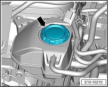
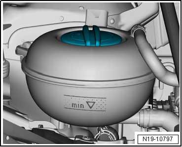
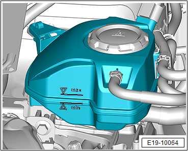
Protected by copyright. Copying for private or commercial purposes, in part or in whole, is not– Carefully open filler cap -arrow- on coolant expansion tank. permitted unless authorised by SEAT S.A. SEAT S.A does not guarantee or accept any liability with respect to the correctness of information in this document. Copyright by SEAT S.A.
Ateca, Leon 2013
Note
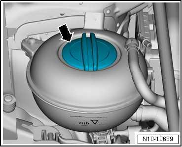
Different caps might be installed depending on the model year.
– Open filler cap -arrow- of coolant expansion tank.
Toledo 2013, Ibiza 2016
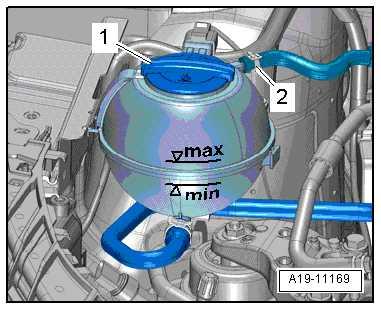
– Open filler cap -1- on coolant expansion tank.
Note
Disregard item -2-.
Continued for all vehicles
– Fit cooling system tester - V.A.G 1274 B- with adapter V.A.G 1274/8- to coolant expansion tank. – Using hand pump on tester, build up a pressure of approx. 1.5 bar.
• The pressure must not drop by more than 0.2 bar within 10 mi‐nutes.
– If pressure drops by more than 0.2 bar, locate leaks and rectify faults.
Note
Protected by copyright. Copying for private or commercial purposes, in part or in whole, is not permitted unless authorised by SEAT S.A. SEAT S.A does not guarantee or accept any liability with respect to the correctness of information in this document. Copyright by SEAT S.A.
♦ The pressure drop by more than 0.2 bar within 10 minutes is caused by the coolant which cools down. ♦ The colder the engine, the lower the pressure loss. ♦ If necessary, repeat the check while the engine is cold.
Check pressure relief valve in cap. – Fit cooling system tester - V.A.G 1274 B- with adapter V.A.G 1274/9- onto coolant filler cap. – Build up pressure using hand pump of cooling system tester. Blue cap ♦ The pressure relief valve should open at a pressure of 1.4 bar. Black cap ♦ The pressure relief valve must open at a pressure of 1.6 … 1.8 bar.
1.3 Draining and adding coolant
⇒ “1.3.1 Draining and adding coolant, Ateca, Leon 2013”, page 260 ⇒ “1.3.2 Draining and adding coolant, Ibiza 2018, Arona”, page 265 ⇒ “1.3.3 Draining and adding coolant, Toledo 2013, Ibiza 2016”, page 271
Special tools and workshop equipment required
Protected by copyright. Copying for private or commercial purposes, in part or in whole, is not permitted unless authorised by SEAT S.A. SEAT S.A does not guarantee or accept any liability with respect to the correctness of information in this document. Copyright by SEAT S.A.
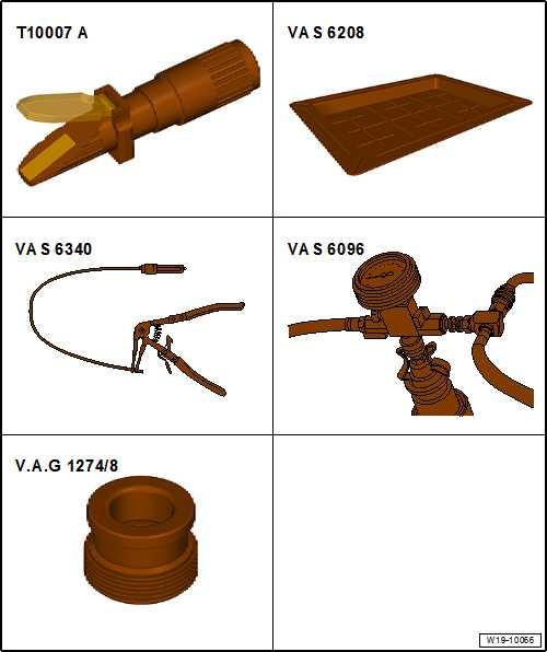
♦ Refractometer - T10007A-
♦ Drip tray for workshop hoist - VAS 6208♦ Hose clamp pliers - VAS 6340♦ Coolant system charge unit - VAS 6096♦ Adapter for cooling system tester - V.A.G 1274/8♦ Cooling system tester - V.A.G 1274 B♦ Safety glasses ♦ Safety gloves Draining
CAUTION
On a warm engine, the cooling system is under high pressure. Danger of scalding by steam and hot coolant. Skin and other parts of the body may be scalded. – Wear protective gloves. – Wear protective goggles. – Reduce excess pressure by covering cap of coolant expan‐sion tank with cloths and opening it carefully.
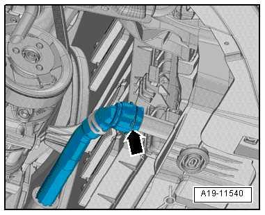
– Carefully open filler cap -arrow- on coolant expansion tank. – Remove noise insulation ⇒ General body repairs, exterior; Rep. gr. 66 ; Noise insulation; Removing and installing noise insulation .
Note
Collect drained coolant in a clean container for re-use or disposal.
– Place drip tray for workshop hoist - VAS 6208- beneath en‐gine.
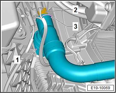
– Disconnect connector -2- on radiator outlet coolant tempera‐ture sender - G83- .
– Loosen retaining clip -1-, remove lower left coolant hose from radiator and drain off coolant.

Protected by copyright. Copying for private or commercial purposes, in part or in whole, is not permitted unless authorised by SEAT S.A. SEAT S.A does not guarantee or accept any liability with respect to the correctness of information in this document. Copyright by SEAT S.A.
– Release retaining clip -arrow-, remove lower right coolant hose from radiator for charge air cooling circuit and drain off remaining coolant. Filling
Protected by copyright. Copying for private or commercial purposes, in part or in whole, is not permitted unless authorised by SEAT S.A. SEAT S.A does not guarantee or accept any liability with respect to the correctness of information in this document. Copyright by SEAT S.A.
Note
♦ The water used for mixing has a major influence on the effec‐tiveness of the coolant. Because the water quality differs from country to country and even from region to region, the quality of the water to be used in the cooling system has been speci‐fied by Volkswagen. Distilled water fulfils all requirements. Therefore, always use only distilled water when mixing coolant for topping up or renewing coolant. ♦ Use only coolant additives which conform with the ⇒ Elec‐tronic parts catalogue (ETKA) . Other coolant additives may reduce corrosion protection substantially. The resulting dam‐age could lead to loss of coolant and subsequent severe damage to the motor. ♦ Mixed in the proper proportions, coolant inhibits frost and cor‐rosion damage as well as scaling. It also raises the boiling point of coolant. For this reason, the cooling system must be filled all-year-round with coolant additives. ♦ Because of its high boiling point, the coolant improves engine reliability under heavy loads, particularly in countries with trop‐ical climates.
♦ Use ONLY refractometer - T10007A- for determining current anti-freeze value.
♦ The frost protection must be effective down to at least -25 °C, and approx. -36 °C in cold countries. The effectiveness of the frost protection may only be increased if a higher level of frost protection is required due to the climate. It may, however, be increased only to a maximum of -48°C. Otherwise, the cooling effect will be impaired. ♦ Do not reduce the coolant concentration by adding water even in warmer seasons and in warmer countries. Frost protection must be guaranteed down to at least -25 °C. ♦ Read off anti-freeze figures for respective replenished coolant additives.
♦ The temperature read off the refractometer - T10007A- corre‐sponds the »ice flocculation point«. Flakes of ice may start forming in the coolant at this temperature. ♦ Never reuse old coolant.
♦ Use only a water/coolant additive mixture as a slip agent for coolant hoses.

Coolant mixture ratio
Frost protection to
-25 °C -36 °C Coolant additive concentration
40 % 50 % Coolant ad‐ditive 1)
3.2 l 4.0 l Distilled wa‐ter 1)
4.8 l 4.0 l
1) The quantity of coolant can vary depending on the vehicle equipment. • Protected by copyright. Copying for private or commercial purposes, in part or in whole, is notCoolant ⇒ Electronic parts catalogue permitted unless authorised by SEAT S.A. SEAT S.A does not guarantee or accept any liability with Procedure respect to the correctness of information in this document. Copyright by SEAT S.A.
– Reconnect coolant hoses with plug-in connectors ⇒ page 306 .
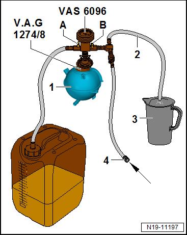
– Fill coolant reservoir of -VAS 6096- with at least 8 litres of premixed coolant in correct mixture ratio:
– Screw adapter for cooling system tester - V.A.G 1274/8- onto coolant expansion tank. – Mount cooling system charge unit - VAS 6096- on adapter V.A.G 1274/8- .
– Feed vent hose -2- into a small container -3-.
Note
Exhaust air takes a slight quantity of coolant along with it; this should be collected.
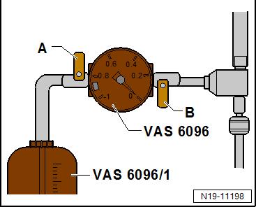
– Close valves -A- and -B- (turn lever transverse to direction of flow to do this). – Connect hose -3- to compressed air. • 6 ... 10 bar pressure
– Open valve -B-; turn lever in direction of flow to do this. • The suction-jet pump reduces pressure in the cooling system to below atmospheric pressure. The needle on the gauge should move into the green zone. – Also briefly open valve -A- (turn lever in direction of flow to do this) so that the hose on the coolant expansion tank of VAS 6096- fills with coolant.
– Close valve -A- again. – Leave valve -B- open for a further 2 minutes. • The suction-jet pump will continue generating a vacuum in the cooling system. The needle on the gauge must remain in the green zone. – Close valve -B-.
• The needle on the gauge must stay in the green zone. The vacuum in the cooling system is then sufficient for subsequent filling.
Note
♦Protected by copyright. Copying for private or commercial purposes, in part or in whole, is notIf the needle does not reach the green zone, repeat the proc‐ess. permitted unless authorised by SEAT S.A. SEAT S.A does not guarantee or accept any liability with respect to the correctness of information in this document. Copyright by SEAT S.A. ♦ If vacuum drops, cooling system must be checked for leaks.
– Detach the compressed air hose. – Open valve -A-. • The vacuum in the cooling system causes the coolant to be drawn out of the coolant expansion tank of -VAS 6096- ; the cooling system is then filled. – Remove cooling system charge unit - VAS 6096- from coolant expansion tank.
– Fill coolant up to “max.” mark. – Install noise insulation ⇒ General body repairs, exterior; Rep. gr. 66 ; Noise insulation; Assembly overview – noise insula‐tion .
– On vehicles with auxiliary heater, switch on auxiliary heater for about 30 seconds.
– Set temperature regulator to “HI”. – Switch off air conditioner compressor. To do this, press AC button.
• LED in the button must not light up. – Start engine and run it for max. 2 min. at a speed of approx. 1500 rpm. – Fill coolant up to the overflow hole of the coolant expansion tank while the engine is running. – Tighten cap of coolant expansion tank until it engages. – Run engine at idling speed until both large coolant hoses on radiator are heated up. – Switch off engine and let it cool off.
– Check coolant level.
• The coolant level must be between the “min. mark” and the “max. mark” when the engine is cold. • When the engine is at operating temperature, it is permissible that the coolant level is at the “max. mark” or above.
– Top up with coolant again if necessary.
Protected by copyright. Copying for private or commercial purposes, in part or in whole, is not permitted unless authorised by SEAT S.A. SEAT S.A does not guarantee or accept any liability with respect to the correctness of information in this document. Copyright by SEAT S.A. 1.3.2 Draining and adding coolant, Ibiza 2018, Arona
Special tools and workshop equipment required
Protected by copyright. Copying for private or commercial purposes, in part or in whole, is not permitted unless authorised by SEAT S.A. SEAT S.A does not guarantee or accept any liability with respect to the correctness of information in this document. Copyright by SEAT S.A.
♦ Refractometer - T10007 A-
♦ Drip tray for workshop hoist - VAS 6208♦ Hose clip pliers - VAS 6340♦ Coolant system charge unit - VAS 6096♦ Adapter for cooling system tester - V.A.G 1274/8♦ Cooling system tester - V.A.G 1274 B♦ Safety glasses
♦ Safety gloves Draining
CAUTION
If the engine is hot, the coolant system is exposed to high pres‐sure. Danger of scalding by steam and hot coolant. Skin and other parts of the body may be scalded. – Wear protective gloves. – Wear protective goggles. – Reduce excess pressure by covering cap of coolant expan‐sion tank with cloths and opening it carefully.
– Carefully open filler cap -arrow- on coolant expansion tank. – Remove noise insulation ⇒ General body repairs, exterior; Rep. gr. 66 ; Noise insulation; Removing and installing noise insulation .
Note
Collect drained coolant in a clean container for re-use or disposal.
– Place drip tray for workshop hoist - VAS 6208- beneath en‐gine.
Vehicles with radiator, version 1:
– Disconnect connector -2- on radiator outlet coolant tempera‐ture sender - G83- .
Protected by copyright. Copying for private or commercial purposes, in part or in whole, is not permitted unless authorised by SEAT S.A. SEAT S.A does not guarantee or accept any liability with respect to the correctness of information in this document. Copyright by SEAT S.A. – Slightly lift retaining clip -1-, disconnect coolant hose from ra‐diator (bottom left) and drain off coolant.
– Lift retaining clip -arrow- a little, disconnect coolant hose from water radiator (bottom right) for charge air cooling circuit and drain off remaining coolant.
Vehicles with radiator, version 2:
– Disconnect connector -2- on radiator outlet coolant tempera‐ture sender - G83- .
– Slightly lift retaining clip -1-, disconnect coolant hose from ra‐diator (bottom left) and drain off coolant.
– Slightly lift retaining clips -1- and -2-, disconnect coolant hoses from radiator (bottom right) and drain off remaining coolant. Continued for all vehicles:
Protected by copyright. Copying for private or commercial purposes, in part or in whole, is not permitted unless authorised by SEAT S.A. SEAT S.A does not guarantee or accept any liability with respect to the correctness of information in this document. Copyright by SEAT S.A.
Note
♦ The water used for mixing has a major influence on the effec‐tiveness of the coolant. Because the water quality differs from country to country and even from region to region, the quality of the water to be used in the cooling system has been speci‐fied by Volkswagen. Distilled water fulfils all requirements. Therefore, always use only distilled water when mixing coolant for topping up or renewing coolant. ♦ Use only coolant additives which conform with the ⇒ Elec‐tronic parts catalogue (ETKA) . Other coolant additives may reduce corrosion protection substantially. The resulting dam‐age could lead to loss of coolant and subsequent severe damage to the motor. ♦ Mixed in the proper proportions, coolant inhibits frost and cor‐rosion damage as well as scaling. It also raises the boiling point of coolant. For this reason, the cooling system must be filled all-year-round with coolant additives. ♦ Because of its high boiling point, the coolant improves engine reliability under heavy loads, particularly in countries with trop‐ical climates.
♦ Use ONLY refractometer - T10007A- for determining current anti-freeze value.
♦ The frost protection must be effective down to at least -25 °C, and approx. -36 °C in cold countries. The effectiveness of the frost protection may only be increased if a higher level of frost protection is required due to the climate. It may, however, be increased only to a maximum of -48°C. Otherwise, the cooling effect will be impaired. ♦ Do not reduce the coolant concentration by adding water even in warmer seasons and in warmer countries. Frost protection must be guaranteed down to at least -25 °C. ♦ Read off anti-freeze figures for respective replenished coolant additives.
♦ The temperature read off the refractometer - T10007A- corre‐sponds the »ice flocculation point«. Flakes of ice may start forming in the coolant at this temperature. ♦ Never reuse old coolant.
♦ Use only a water/coolant additive mixture as a slip agent for coolant hoses.
Filling Coolant mixture ratio
• Coolant (40 %) and distilled water (60 %) for frost protection to -25 °C
• Coolant (50 %) and distilled water (50 %) for frost protection to -36 ℃
•Protected by copyright. Copying for private or commercial purposes, in part or in whole, is not permitted unless authorised by SEAT S.A. SEAT S.A does not guarantee or accept any liability withCoolant: ⇒ Electronic parts catalogue (ETKA) Procedure respect to the correctness of information in this document. Copyright by SEAT S.A.
– Reconnect coolant hoses with plug-in connectors ⇒ page 308 .
– Fill coolant expansion tank of -VAS 6096- with at least 10 litres of pre-mixed coolant in correct mixture ratio. – Screw adapter for cooling system tester - V.A.G 1274/8- onto coolant expansion tank. – Mount cooling system charge unit - VAS 6096- on adapter V.A.G 1274/8- .
– Feed vent hose -2- into a small container -3-.
Note
Exhaust air takes a slight quantity of coolant along with it; this should be collected.
– Close valves -A- and -B- (turn lever transverse to direction of flow to do this). – Connect hose -3- to compressed air. • 6 ... 10 bar of working pressure.
– Open valve -B-; turn lever in direction of flow to do this. • The suction-jet pump reduces pressure in the cooling system to below atmospheric pressure. The needle on the gauge should move into the green zone. – Also briefly open valve -A- (turn lever in direction of flow to do this) so that the hose on the coolant expansion tank of VAS 6096- fills with coolant.
– Close valve -A- again. – Leave valve -B- open for a further 2 minutes. • The suction-jet pump will continue generating a vacuum in the cooling system. The needle on the gauge must remain in the green zone. – Close valve -B-.
• The needle on the gauge must stay in the green zone. The vacuum in the cooling system is then sufficient for subsequent filling.
Note
Protected by copyright. Copying for private or commercial purposes, in part or in whole, is not permitted unless authorised by SEAT S.A. SEAT S.A does not guarantee or accept any liability with respect to the correctness of information in this document. Copyright by SEAT S.A.
♦ If the needle does not reach the green zone, repeat the proc‐ess.
♦ If vacuum drops, cooling system must be checked for leaks.
– Detach the compressed air hose. – Open valve -A-. • The vacuum in the cooling system causes the coolant to be drawn out of the coolant expansion tank of -VAS 6096- ; the cooling system is then filled. – Remove cooling system charge unit - VAS 6096- from coolant expansion tank.
– Fill coolant up to “max.” mark. – Install noise insulation ⇒ General body repairs, exterior; Rep. gr. 66 ; Noise insulation; Assembly overview – noise insula‐tion .
– On vehicles with auxiliary heater, switch on auxiliary heater for about 30 seconds.
– Set temperature regulator to “HI”. – Switch off air conditioner compressor. To do this, press AC button.
• LED in the button must not light up. – Start engine and run it for max. 2 min. at a speed of approx. 1500 rpm. – Fill coolant up to the overflow hole of the coolant expansion tank while the engine is running. – Tighten cap of coolant expansion tank until it engages. – Run engine at idling speed until both large coolant hoses on radiator are heated up. – Switch off engine and let it cool off.
– Check coolant level.
• The coolant level must be between the “min. mark” and the “max. mark” when the engine is cold. • When the engine is at operating temperature, it is permissible that the coolant level is at the “max. mark” or above.
– Top up with coolant again if necessary.
1.3.3 Draining and adding coolant, Toledo 2013, Ibiza 2016
Protected by copyright. Copying for private or commercial purposes, in part or in whole, is not permitted unless authorised by SEAT S.A. SEAT S.A does not guarantee or accept any liability with respect to the correctness of information in this document. Copyright by SEAT S.A.


