7 minute read
3.3 Removing and installing camshaft oil seal


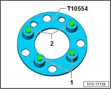
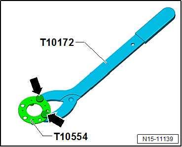
Counter-hold tool - T10554-
• Pins -1- and -2- are located at different distances to the coun‐ter-hold tool - T10554- .
• The counter-hold tool - T10554- can be inserted in only one position. • Fit counter-hold tool - T10554- so that it rests flat against cam‐shaft adjusters. Procedure
Note
♦ Protect the toothed belt from escaping engine oil. ♦ Seal camshaft adjusters immediately using suitable plug from engine bung set - VAS 6122- .
– Place a cloth underneath to catch escaping engine oil. – Thoroughly clean any cavities which have been filled with en‐gine oil. – Set engine to “TDC for cylinder no. 1” ⇒ “4.7 Setting piston to TDC position”, page 155 .
– Unscrew bolt -1-.
– Release clips -2-. – Unclip bracket -4-. – Remove toothed belt cover -3-.
– Unscrew bolts -arrows- of exhaust camshaft.

– The camshaft must be turned to gain access to all bolts. – Remove camshaft clamp - T10494- before turning camshaft. – After camshaft clamp - T10494- has been removed, turn cam‐shaft until all remaining bolts have been reached. – Remove cover from camshaft adjuster of exhaust camshaft. – Set engine to “TDC for cylinder no. 1”, and insert camshaft clamp - T10494- ⇒ “2.5 Checking valve timing”, page 187 .
Note
Protected by copyright. Copying for private or commercial purposes, in part or in whole, is not permitted unless authorised by SEAT S.A. SEAT S.A does not guarantee or accept any liability with respect to the correctness of information in this document. Copyright by SEAT S.A.

The camshaft clamp - T10494- must not be used as a counterhold tool.
Exhaust camshaft
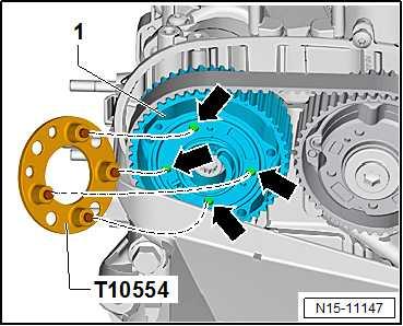
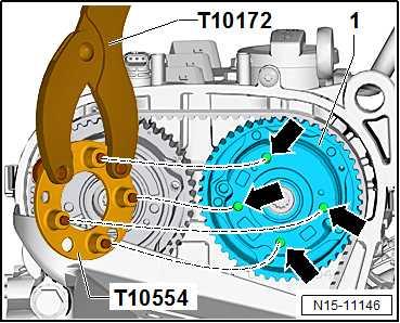
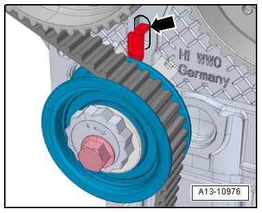
– Guide in counter-hold tool - T10554- between camshaft ad‐juster and engine support. – To do this, initially guide through counter-hold tool - T10554between pins -2- on camshaft adjuster.
– Turn counter-hold tool - T10554- so that it can be inserted into holes -arrows- as shown in illustration.
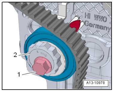
– Fit counter-hold tool - T10554- so that it rests flat against cam‐shaft adjuster -1-.
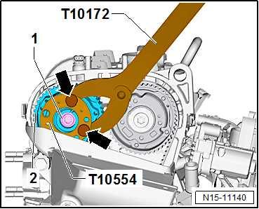
– Loosen bolt -1- one turn. Hold camshaft pulley in place using counter-hold tool - T10554- and counter-hold tool - T10172A- .
Protected by copyright. Copying for private or commercial purposes, in part or in whole, is not permitted unless authorised by SEAT S.A. SEAT S.A does not guarantee or accept any liability with respect to the correctness of information in this document. Copyright by SEAT S.A.
Inlet camshaft
– Assemble tools as shown in illustration.
– Bolt on counter-hold tool - T10172A- and counter-hold tool T10554- with knurled screws -arrows-.
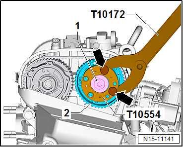
– Fit counter-hold tool - T10554- with counter-hold tool T10172A- to camshaft pulley -1- as shown in illustration. – The pins must be inserted properly into holes -arrows-. – Fit counter-hold tool - T10554- so that it rests flat against cam‐shaft adjuster -1-. – Secure camshaft against turning with counterhold - T10554and counterhold - T10172A- .
– Unscrew plug -1- for camshaft pulley on inlet camshaft. – Use counter-hold tool - T10554- with counter-hold tool T10172A- to do this.
– Loosen bolt -1- one turn. Hold camshaft pulley in place using counter-hold tool - T10554- and counter-hold tool - T10172A- .
Continuation for both sides:
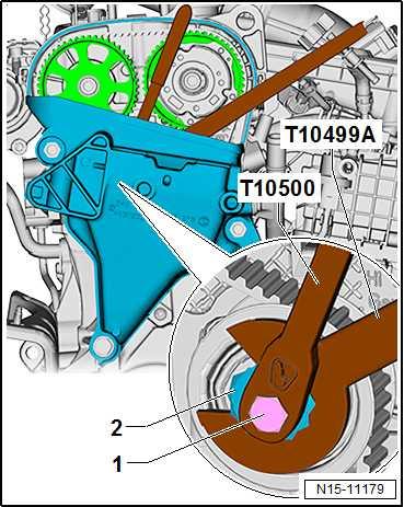
– Fit special wrench, 30 mm - T10499A- on eccentric adjuster -2- of tensioning roller. – Loosen bolt -1- using insert tool, 13 mm - T10500- . – Release tensioning roller on eccentric adjuster -2- using spe‐cial wrench, 30 mm - T10499A- .
– Remove toothed belt from camshaft pulleys.
Protected by copyright. Copying for private or commercial purposes, in part or in whole, is not permitted unless authorised by SEAT S.A. SEAT S.A does not guarantee or accept any liability with respect to the correctness of information in this document. Copyright by SEAT S.A.
Bend radius of toothed belt
NOTICE
Risk of damage to toothed belt by bending it excessively. The toothed belt is made of glass fibre fabric which will be damaged if it is bent excessively. – Never bend toothed belt to a radius less than r = 25 mm.
• The bend radius -r- on the toothed belt -2- should therefore not be below 25 mm (approx. half the diameter of gear -1- on crankshaft). – Install toothed belt ⇒ “2.6 Adjusting valve timing”, page 189 . Specified torques ♦ ⇒ “2.2 Assembly overview - toothed belt”, page 174 ♦ ⇒ “3.1 Assembly overview - valve gear”, page 204 ♦ ⇒ “3.1 Assembly overview - crankcase breather system”, page 247
♦ ⇒ “1.1 Assembly overview - turbocharger”, page 351 ♦ ⇒ “2.1 Assembly overview - charge air system”, page 363
2.8 Removing and installing tensioning roll‐er
Removing – Remove camshaft adjuster for inlet camshaft ⇒ page 211 . – Detach toothed belt from the tensioning roller. – Unscrew bolt -1-.
– Remove tensioning roller -2-.
Protected by copyright. Copying for private or commercial purposes, in part or in whole, is not permitted unless authorised by SEAT S.A. SEAT S.A does not guarantee or accept any liability withInstalling respect to the correctness of information in this document. Copyright by SEAT S.A. Install in reverse order of removal, observing the following: – Install tensioning roller. • The sheet-metal tab -arrow- of the tensioning roller must en‐gage in the cast notch in the cylinder head. – Install camshaft adjuster for inlet camshaft ⇒ page 211 . Specified torques ♦ ⇒ “2.2 Assembly overview - toothed belt”, page 174 ♦ ⇒ “1.2 Assembly overview - camshaft housing”, page 160 ♦ ⇒ “2.1 Assembly overview - charge air system”, page 363

3 Valve gear
⇒ “3.1 Assembly overview - valve gear”, page 204 ⇒ “3.2 Measuring axial play of camshaft”, page 205 ⇒ “3.3 Removing and installing camshaft oil seal”, page 206 ⇒ “3.4 Removing and installing camshaft adjuster”, page 211 ⇒ “3.5 Removing and installing inlet camshaft control valve 1 N205 ”, page 220 ⇒ “3.6 Removing and installing exhaust camshaft control valve 1 N318 ”, page 221 ⇒ “3.7 Removing and installing valve stem seals”, page 221
Protected by copyright. Copying for private or commercial purposes, in part or in whole, is not permitted unless authorised by SEAT S.A. SEAT S.A does not guarantee or accept any liability with3.1 Assembly overview - valve gearrespect to the correctness of information in this document. Copyright by SEAT S.A.
1 - Inlet valve ❑ Do not rework, only lap‐ping-in is permitted. ❑ Valve dimensions ⇒ “4.3 Valve dimen‐sions”, page 232 ❑ Checking valve guides ⇒ “4.1 Checking valve guides”, page 231 2 - Outlet valve ❑ Do not rework, only lap‐ping-in is permitted. ❑ Valve dimensions ⇒ “4.3 Valve dimen‐sions”, page 232 ❑ Checking valve guides ⇒ “4.1 Checking valve guides”, page 231 3 - Cylinder head ❑ Removing and installing ⇒ “1.3 Removing and in‐stalling cylinder head”, page 162 ❑ Check for distortion ⇒ page 160 . 4 - Valve stem seal ❑ Renewing ⇒ “3.7 Removing and in‐stalling valve stem seals”, page 221 5 - Valve springs ❑ Fitting position ⇒ page 205 6 - Valve spring plate 7 - Cotters
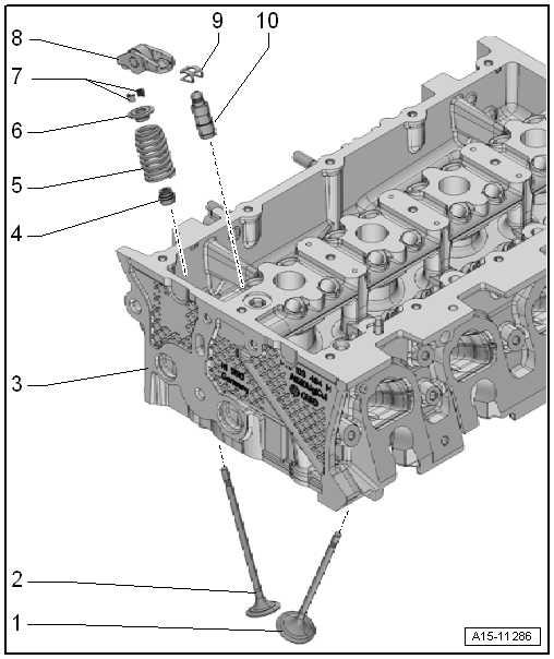
8 - Roller rocker fingers ❑ Removing and installing ⇒ “1.4 Removing and installing camshaft housing”, page 166 ❑ Mark installation position for re-installation. ❑ Check roller bearing for ease of movement.


