5 minute read
2.7 Removing toothed belt from camshaft


– To do this, turn camshafts with adapter for angle sensor - VAS 611 007/5- -E-.
– Hold camshafts via adapter for angle sensor - VAS 611 007/9and adapter for angle sensor - VAS 611 007/10- -E- in 0.0° position with a wrench.
Note
♦ The camshafts tend to turn.
♦ Use a hexagon key to hold the camshafts in 0.0° position. ♦ Always remove the hexagon key after the camshafts have been tightened.
– Tighten brakes after adjustment has been completed. – Tighten bolts -a- for brakes to 11 Nm on both sides.
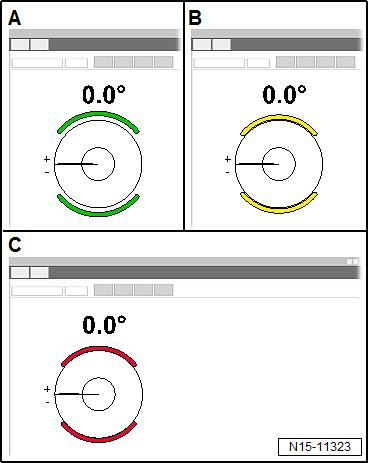
– Make sure that brake indicator on display is red -C-. • It must not be yellow or green.
– Unscrew locking pin - T10340- -A-. – Tighten intake camshaft adjusted using pre-tension procedure ⇒ “3.4.1 Removing and installing camshaft adjuster for inlet camshaft”, page 211 . – Tighten camshaft adjuster on exhaust camshaft to specified initial torque ⇒ “3.4.2 Removing and installing camshaft adjuster for ex‐haust camshaft”, page 215 .
Protected by copyright. Copying for private or commercial purposes, in part or in whole, is not permitted unless authorised by SEAT S.A. SEAT S.A does not guarantee or accept any liability with respect to the correctness of information in this document. Copyright by SEAT S.A.

– Make sure that bolts -a- for brakes are released on both sides.
– Make sure that brake indicator on display is green -A-. – It must not be yellow or red.
Protected by copyright. Copying for private or commercial purposes, in part or in whole, is not permitted unless authorised by SEAT S.A. SEAT S.A does not guarantee or accept any liability with respect to the correctness of information in this document. Copyright by SEAT S.A.
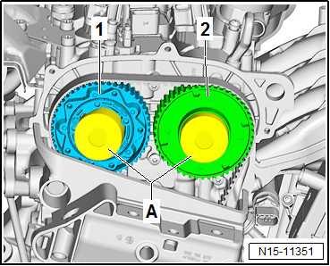
– Seal camshaft adjusters -1- and -2- using suitable plugs -Afrom engine bung set - VAS 6122- . – Fit a piece of paper -A- into plugs to catch the engine oil. – The plug for the camshaft adjuster -1- on exhaust side must be pushed in slightly. – Turn crankshaft 2 turns in direction of rotation of engine.
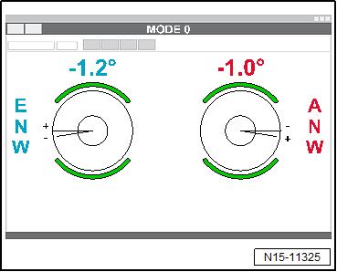
Determining correction angle – Screw in locking pin - T10340- . – Set piston for cylinder no. 1 to TDC position ⇒ “4.7 Setting piston to TDC position”, page 155 . – Read valve timing on display and write down values. The il‐lustration shows values as an example.
Note
♦ The correction angle is determined for each individual vehicle. ♦ The value read after the engine has been cranked is used for determining the correction angle. ♦ Note the algebraic signs of the values. ♦ The correction angle results from the difference between the specification and the value which has been read after the crankshaft has been cranked twice.
♦ The correction angle is used to adjust the valve timing.
Example:
Protected by copyright. Copying for private or commercial purposes, in part or in whole, is not permitted unless authorised by SEAT S.A. SEAT S.A does not guarantee or accept any liability with respect to the correctness of information in this document. Copyright by SEAT S.A.Angle in ° Inlet camshaft Exhaust camshaft
Value read after turning crankshaft 2 turns in direction of engine rotation
Specified angle
Determined correction angle -1.2°
+1.1°±1.5°
+2.3° -1.0°
+0.8°±1.5°
+1.8°
Read value ± correction angle = specification Computational example for intake camshaft: -1.2° + 2.3° = 1.1° Computational example for exhaust cam‐shaft: -1.0° + 1.8° = +0.8°
– Set determined correction angle for camshafts. Setting valve timing with correction angle – Place a cloth underneath camshaft adjuster to catch any en‐gine oil which runs out. – Remove plug taken from engine bung set - VAS 6122- from camshaft adjusters. – Remove paper from plugs and camshaft adjusters. – Clean camshaft adjusters with a cleaning cloth, and remove as much engine oil as possible. – Loosen camshaft adjuster on intake side ⇒ “3.4.1 Removing and installing camshaft adjuster for inlet camshaft”, page 211 . – Loosen camshaft adjuster on exhaust side ⇒ “3.4.2 Removing and installing camshaft adjuster for ex‐haust camshaft”, page 215 .
NOTICE
Risk of damage to engine caused by incorrect valve timing. – Do not turn crankshaft out of TDC position.
– Make sure that the piston in cylinder no. 1 is at TDC position ⇒ “4.7 Setting piston to TDC position”, page 155 . – Make sure that bolts -a- for brakes are released on both sides.
– Make sure that brake indicator on display is green -A-. – It must not be yellow or red.
– Set the two camshafts to the determined correction angle ⇒ page 194 . – To do this, turn camshafts with adapter for angle sensor - VAS 611 007/9- and adapter for angle sensor - VAS 611 007/10-E-.
If the valve timing has been set: – Tighten bolts -a- for brakes to 11 Nm on both sides.
Protected by copyright. Copying for private or commercial purposes, in part or in whole, is not permitted unless authorised by SEAT S.A. SEAT S.A does not guarantee or accept any liability with respect to the correctness of information in this document. Copyright by SEAT S.A.
– Make sure that brake indicator on display is red -C-. – It must not be yellow or green.
– Unscrew locking pin - T10340- -A-. – Tighten intake camshaft adjusted using pre-tension procedure
Protected by copyright. Copying for private or commercial purposes, in part or in whole, is not permitted unless authorised by SEAT S.A. SEAT S.A does not guarantee or accept any liability with ⇒ “3.4.1 Removing and installing camshaft adjuster for inlet camshaft”, page 211 . respect to the correctness of information in this document. Copyright by SEAT S.A. – Tighten camshaft adjuster on exhaust camshaft to specified initial torque ⇒ “3.4.2 Removing and installing camshaft adjuster for ex‐haust camshaft”, page 215 .
– Release brakes -a- on both sides.


