
4 minute read
1.4 Removing and installing camshaft housing


Checking cylinder head for distortion – Use straight edge 500 mm - VAS 6075- and feeler gauge to measure cylinder head for distortion at several points. • Max. permissible distortion: 0.05 mm
1.2 Assembly overview - camshaft housing
1 - Seal ❑ Renew after removal
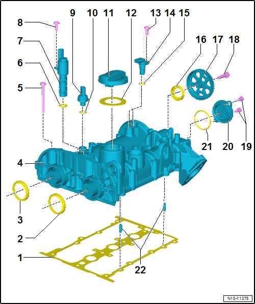
2 - Seal ❑ For inlet camshaft (pul‐ley end) ❑ Renewing ⇒ “3.3.1 Removing and installing camshaft oil seal, inlet camshaft”, page 206 3 - Seal ❑ For exhaust camshaft (pulley end) ❑ Renewing ⇒ “3.3.2 Removing and installing camshaft oil seal, exhaust camshaft, pulley end”, page 208 4 - Camshaft case ❑ Removing and installing ⇒ “1.4 Removing and in‐stalling camshaft hous‐ing”, page 166
Protected by copyright. Copying for private or commercial purposes, in part or in whole, is not permitted unless authorised by SEAT S.A. SEAT S.A does not guarantee or accept any liability with5 - Bolt respect to the correctness of information in this document. Copyright by SEAT S.A. ❑ Specified torque and tightening sequence ⇒ page 162 ❑ Renew after removal

6 - O-ring ❑ Check O-ring for dam‐age. ❑ O-ring not available as a separate part; renew to‐gether with camshaft control valve 1 - N205- if damaged. 7 - Camshaft adjustment valve ❑ Inlet side: camshaft control valve 1 - N205❑ Removing and installing ⇒ “3.5 Removing and installing inlet camshaft control valve 1 N205 ”, page 220 ❑ Exhaust side camshaft control valve 1 - N318-
❑ Removing and installing ⇒ “3.6 Removing and installing exhaust camshaft control valve 1 N318 ”, page 221
8 - Bolt ❑ 8 Nm
9 - Exhaust gas pressure sensor 1 - G450❑ only remove and install ❑ for engines with particulate filter ⇒ “5.4 Removing and installing exhaust gas pressure sensor 1 G450 ”, page 410 ❑ Renew after removal ❑ 25 Nm
10 - Seal ❑ only for engines with particulate filter ❑ Only available in conjunction with exhaust gas pressure sensor 1 - G45011 - Seal ❑ For sealing cover 12 - Cap 13 - Hall sender ❑ Inlet side Hall sender - G40❑ Exhaust side Hall sender 3 - G163❑ Assembly overview ⇒ “1.1 Assembly overview - ignition system”, page 464 14 - Bolt ❑ 8 Nm
15 - O-ring ❑ Renew after removal
16 - Seal ❑ For exhaust camshaft, gearbox end ❑ Renewing ⇒ “3.3.3 Removing and installing camshaft oil seal, exhaust camshaft, gearbox end”, page 209 17 - Toothed belt pulley ❑ For coolant pump ❑ Removing and installing ⇒ “2.7 Removing and installing toothed belt pulley for coolant pump”, page 294 18 - Bolt ❑ Renewing ❑ 20 Nm +90°
19 - Cap 20 - Bolt ❑ 8 Nm
21 - O-ring ❑ Renew after removal
22 - Pins
Protected by copyright. Copying for private or commercial purposes, in part or in whole, is not permitted unless authorised by SEAT S.A. SEAT S.A does not guarantee or accept any liability with respect to the correctness of information in this document. Copyright by SEAT S.A.
Camshaft housing - specified torque and tightening sequence
Note
The bolts (expansion bolts) that are subjected to a goniometric tightening must be replaced after being removed.
– Tighten bolts in stages and in the sequence as shown:
Component Specified torque Note Bolts -1 ... 12- 10 Nm +180° Renewing

1.3 Removing and installing cylinder head
Special tools and workshop equipment required ♦ Torque wrench - V.A.G 1331-Protected by copyright. Copying for private or commercial purposes, in part or in whole, is not permitted unless authorised by SEAT S.A. SEAT S.A does not guarantee or accept any liability with respect to the correctness of information in this document. Copyright by SEAT S.A.
♦ Socket insert - T10545-
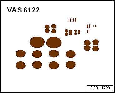
♦ Engine bung set - VAS 6122-
♦ Socket insert - 3410-
♦ Hose clip pliers - VAS 6362-
Removing

Note

♦ Seal open channels of intake and exhaust system with suitable plugs from engine bung set - VAS 6122- . Protected by copyright. Copying for private or commercial purposes, in part or in whole, is not ♦ permitted unless authorised by SEAT S.A. SEAT S.A does not guarantee or accept any liability withCover the openings in the gearbox with a cloth to prevent anyrespect to the correctness of information in this document. Copyright by SEAT S.A.coolant or other liquids from getting into the clutch housing. ♦ Fit the cable ties in the original position when installing. ♦ Attach all heat-shielding sleeves in the same places when in‐stalling.
– Remove camshaft housing ⇒ “1.4 Removing and installing camshaft housing”, page 166 . – Remove intake manifold ⇒ “4.2 Removing and installing intake manifold”, page 400 . – Remove turbocharger ⇒ “1.2 Removing and installing turbocharger”, page 353 . – Disconnect connectors:
1 - On fuel pressure sender - G2472 - On oil pressure sender - G103 - At injectors -N30- , -N31- and -N32-


