4 minute read
1.3 Removing and installing cylinder head


– Screw locking pin - T10340- -A- into cylinder block as far as stop and tighten to 30 Nm. • Bolt head of locking pin - T10340- -A- must contact cylinder block when doing this.
Note
If the locking pin - T10340- -A- cannot be screwed in as far as stop, this indicates that the crankshaft is not in the correct posi‐tion.
– Unscrew locking pin - T10340- -A-. – Turn crankshaft 90° in direction of engine rotation. – Screw locking pin - T10340- -A- into cylinder block as far as stop and tighten to 30 Nm. – Rotate crankshaft in normal direction of rotation as far as stop. The locking pin - T10340- -A- now rests against the crank web.
Note
Locking pin - T10340- -A- locks crankshaft in direction of engine rotation only.
Setting piston from cylinder no. 1 to TDC position for repair work on toothed belt drive and for setting valve timing – Set piston for cylinder no. 1 to TDC position ⇒ page 155 . – Remove air filter housing ⇒ “3.2 Removing and installing air filter housing”, page 397 . – Unclip wiring harness -3- and place to one side. – Remove screws -1-.
– Place a cloth underneath to catch any oil which may drain out. – Remove the plugs -5-. – Pull off pipe -2-. – Remove toothed belt cover -4-.
Protected by copyright. Copying for private or commercial purposes, in part or in whole, is not permitted unless authorised by SEAT S.A. SEAT S.A does not guarantee or accept any liability with respect to the correctness of information in this document. Copyright by SEAT S.A.

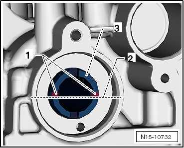
• Grooves -1- of intake camshaft -3- are positioned above the horizontal camshaft centre line -2-.
• Grooves -1- of exhaust camshaft are positioned above hori‐zontal camshaft centre line -2-.
• The centre-line of the holes close to hub of the gear -3- is slightly above the grooves. Specified torques ♦ ⇒ “1.2 Assembly overview - camshaft housing”, page 160 . ♦ ⇒ “2.1 Assembly overview - coolant pump, thermostat”, page 278 . ♦ ⇒ “3.1 Assembly overview - air filter housing”, page 393 .

Protected by copyright. Copying for private or commercial purposes, in part or in whole, is not permitted unless authorised by SEAT S.A. SEAT S.A does not guarantee or accept any liability with respect to the correctness of information in this document. Copyright by SEAT S.A.
15 – Cylinder head, valve gear
1 Cylinder head
⇒ “1.1 Assembly overview - cylinder head”, page 158 ⇒ “1.2 Assembly overview - camshaft housing”, page 160 ⇒ “1.3 Removing and installing cylinder head”, page 162 ⇒ “1.4 Removing and installing camshaft housing”, page 166 ⇒ “1.5 Checking compression”, page 170
1.1 Assembly overview - cylinder head
Note
♦ If an exchange cylinder head is installed, all the contact sur‐faces between the supporting elements, roller rocker fingers and the running surfaces of the cam must be oiled before the cylinder head cover is installed. ♦ Do not remove the plastic packing pieces for protecting the open valves until immediately before fitting cylinder head. ♦ If the cylinder head is renewed, the coolant and engine oil must be renewed as well.
Protected by copyright. Copying for private or commercial purposes, in part or in whole, is not permitted unless authorised by SEAT S.A. SEAT S.A does not guarantee or accept any liability with respect to the correctness of information in this document. Copyright by SEAT S.A.
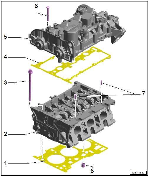
1 - Cylinder head gasket ❑ Renewing ⇒ “1.3 Removing and in‐stalling cylinder head”, page 162 ❑ Observe installation po‐sition: reference num‐ber of the cylinder head 2 - Cylinder head ❑ Removing and installing ⇒ “1.3 Removing and in‐stalling cylinder head”, page 162 ❑ Check for distortion ⇒ page 160 . 3 - Bolt ❑ Renew after removal ❑ pay attention to order for slackening ⇒ page 165 ❑ Specified torque and tightening sequence ⇒ page 159 4 - Seal ❑ Renew after removal
5 - Camshaft case ❑ Removing and installing ⇒ “1.4 Removing and in‐stalling camshaft hous‐ing”, page 166 6 - Bolt ❑ Specified torque and tightening sequence ⇒ page 162 7 - Pins
8 - Dowel sleeve ❑ 2 off
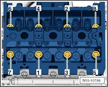
Cylinder head - specified torque and sequence
Note
Protected by copyright. Copying for private or commercial purposes, in part or in whole, is not permitted unless authorised by SEAT S.A. SEAT S.A does not guarantee or accept any liability with respect to the correctness of information in this document. Copyright by SEAT S.A.
The bolts that are subjected to a goniometric retightening must be replaced after being removed.
Bolt
Stage 1
Stage 2
Stage 3
Stage 4 Specified torque Note
40 Nm Renew bolts
Turn 90° further with rigid spanner
Turn 90° further with rigid spanner
Turn 90° further with rigid spanner
– Tighten bolts in stages and in the sequence as shown: