17 minute read
1.4 Installing engine


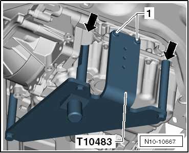
– Push engine support - T10483- to stop into holes -arrows- in cylinder block. – At first, tighten bolts -1- hand-tight.
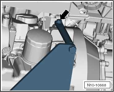
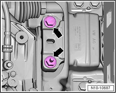
– Initially, tighten bolts -arrow- by hand. – Tighten bolt -arrow- to 20 Nm.
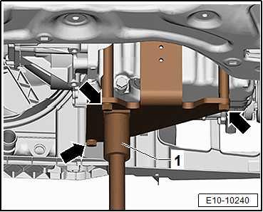
– Tighten all bolts -arrows- of the engine bracket - T10483- on the cylinder block with 20 Nm. – Fit engine and gearbox jack - VAS 6931- to engine support T10483- , and raise engine/gearbox assembly slightly.
Note
Use a stepladder to unscrew the bolts for engine/gearbox mount‐ing.
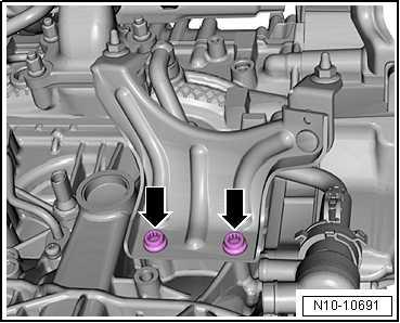
– Unscrew bolts -arrows- for support arm of gearbox mounting completely.
Protected by copyright. Copying for private or commercial purposes, in part or in whole, is not permitted unless authorised by SEAT S.A. SEAT S.A does not guarantee or accept any liability with respect to the correctness of information in this document. Copyright by SEAT S.A.
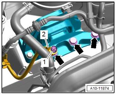

– Unscrew securing bolts -arrows- from gearbox mounting.
Note
♦ Risk of damage to the vacuum lines or electrical wiring as well as damage to the engine compartment. ♦ Check that all vacuum lines and electrical wiring between en‐gine, gearbox, subframe and body have been detached. ♦ Carefully remove the engine/gearbox unit out of the engine bay whilst draining.
– Guide the engine/gearbox assembly as far forwards as pos‐sible and lower it slowly downwards.

1.2 Separating engine and gearbox
⇒ “1.2.1 Separating engine and gearbox - vehicles with manual gearbox”, page 47 ⇒ “1.2.2 Separate engine and gearbox - vehicles with dual clutch gearbox”, page 48
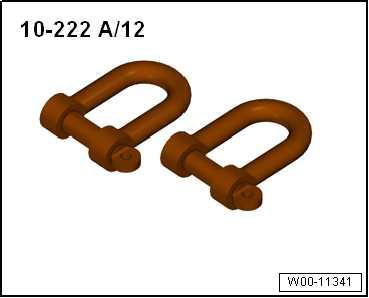
Special tools and workshop equipment required ♦ Hook - 10 - 222 A /12-
Protected by copyright. Copying for private or commercial purposes, in part or in whole, is not permitted unless authorised by SEAT S.A. SEAT S.A does not guarantee or accept any liability with respect to the correctness of information in this document. Copyright by SEAT S.A.
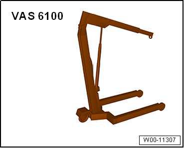
♦ Workshop hoist - VAS 6100-
Procedure
• Engine/gearbox assembly removed and attached to engine bracket - T10483- .
– Remove starter ⇒ Electrical system; Rep. gr. 27 ; Starter; Removing and installing starter .
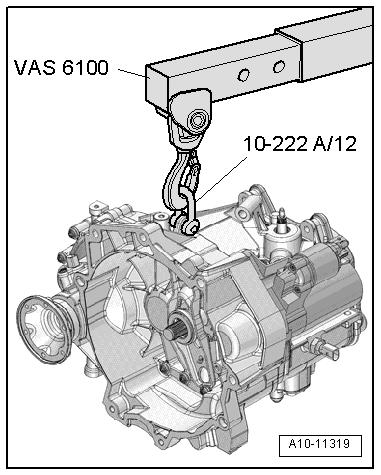
– Attach shackle - 10-222A/12- to gearbox. – Attach workshop hoist - VAS 6100- to shackle - 10-222A/12- .
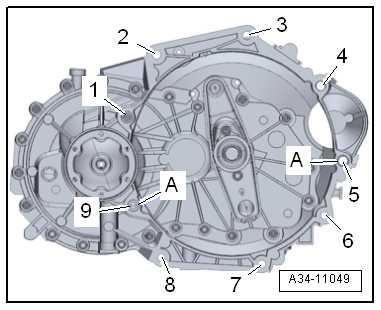
– Unscrew bolts -1, 2, 3- and -6 ... 9- from threaded connection between gearbox and engine.
Note
Protected by copyright. Copying for private or commercial purposes, in part or in whole, is not permitted unless authorised by SEAT S.A. SEAT S.A does not guarantee or accept any liability with respect to the correctness of information in this document. Copyright by SEAT S.A.
Ignore -items 4, 5- and -A-.
– Pull gearbox off engine.
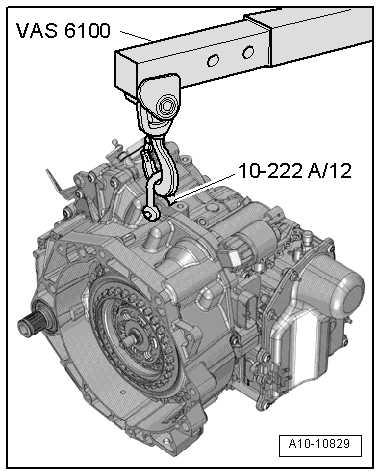
Special tools and workshop equipment required ♦ Shackle - 10 - 222 A /12-
♦ Workshop hoist - VAS 6100-
Procedure
• Engine/gearbox assembly removed and attached to engine bracket - T10497- .
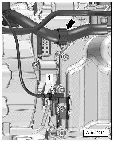
– Place wiring harness to one side -arrow-.
Note
Disregard -item 1-.
– Remove starter ⇒ Electrical system; Rep. gr. 27 ; Starter; Removing and installing starter .
– Secure gearbox to workshop hoist - 10 - 222 A /12- using shackle - VAS 6100- .
Protected by copyright. Copying for private or commercial purposes, in part or in whole, is not permitted unless authorised by SEAT S.A. SEAT S.A does not guarantee or accept any liability with respect to the correctness of information in this document. Copyright by SEAT S.A.
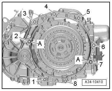
– Unscrew bolts -1 to 8- securing gearbox to engine.
Note
Disregard -item A-.
– Pull gearbox off engine.
1.3 Securing engine on engine and gearbox support
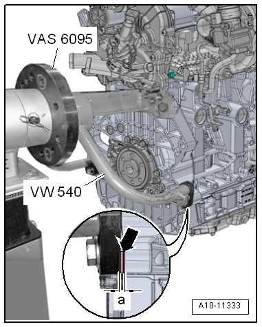
Special tools and workshop equipment required Protected by copyright. Copying for private or commercial purposes, in part or in whole, is not ♦ permitted unless authorised by SEAT S.A. SEAT S.A does not guarantee or accept any liability withEngine and gearbox support - VW 540respect to the correctness of information in this document. Copyright by SEAT S.A.
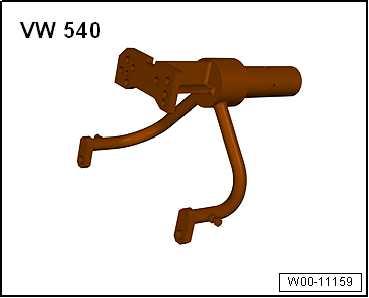
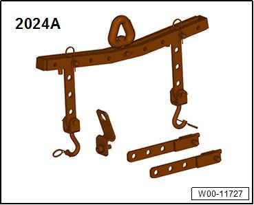
♦ Lifting tackle - 2024 A-
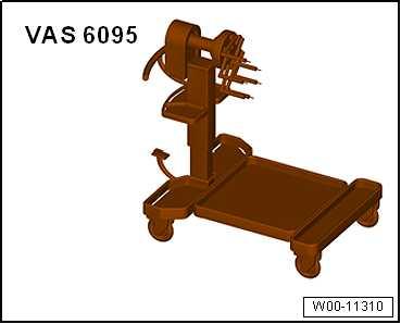
♦ Engine and gearbox support - VAS 6095-
♦ Workshop hoist - VAS 6100-
Procedure
• Engine removed ⇒ “1.1 Removing engine”, page 13 . • Gearbox detached from engine ⇒ “1.2 Separating engine and gearbox”, page 47 . – Attach lifting tackle - 2024 A- on engine and workshop hoist VAS 6100- as shown in illustration.
Note
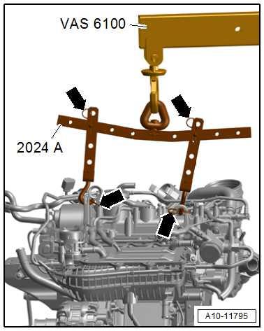
Protected by copyright. Copying for private or commercial purposes, in part or in whole, is not ♦ permitted unless authorised by SEAT S.A. SEAT S.A does not guarantee or accept any liability withRisk of accident due to loose components of lifting tackle.respect to the correctness of information in this document. Copyright by SEAT S.A. ♦ In order to match the lifting tackle to the centre of gravity of the engine, the holes in the hook rail must be allocated as shown in the illustration. ♦ The support hooks and retaining pins on the lifting tackle must be secured with locking pins -arrows-.
– Lift engine off T10483 using workshop hoist - VAS 6100- .
– Secure engine to engine and gearbox support - VW 540- with engine and gearbox support - VAS 6095- , as shown in illus‐tration.
– Insert spacers -arrow-. • Dimension -a- = 10 mm.
1.4 Installing engine
⇒ “1.4.1 Installing engine; Ateca, Leon 2013”, page 52 ⇒ “1.4.2 Installing engine, Ibiza 2018, Arona”, page 57 ⇒ “1.4.3 Installing engine, Toledo 2013, Ibiza 2016”, page 62
1.4.1 Installing engine; Ateca, Leon 2013
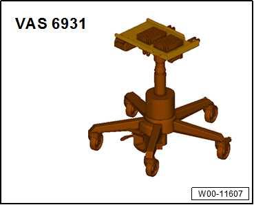
Special tools and workshop equipment required ♦ Engine and gearbox jack - VAS 6931-
♦ Hose clip pliers - VAS 6362-
Protected by copyright. Copying for private or commercial purposes, in part or in whole, is not permitted unless authorised by SEAT S.A. SEAT S.A does not guarantee or accept any liability with respect to the correctness of information in this document. Copyright by SEAT S.A.
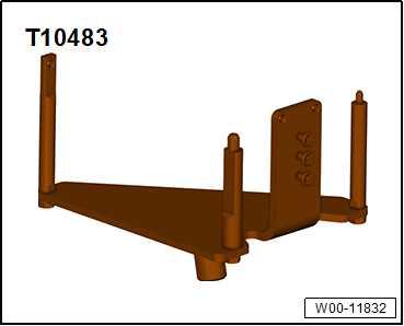
♦ Engine support - T10483-

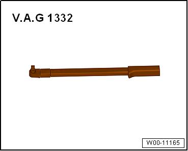
♦ Torque wrench - V.A.G 1332-
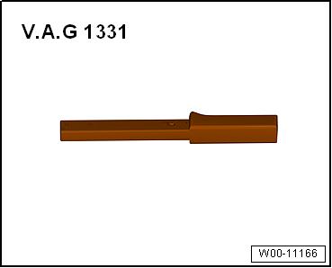
♦ Torque wrench - V.A.G 1331-
Procedure
Note
♦ If a further tightening angle is specified for certain bolts, these must be renewed.
♦ Renew self-locking nuts and bolts, and seals, O-rings and gaskets. ♦ Secure all hose connections with the hose clips corresponding to original equipment ⇒ Electronic Parts Catalogue . ♦ Fit heat shield sleeves in the same place when installing.
– Install intermediate plate ⇒ Fig. ““Installing intermediate plate”“ , page 136 . Vehicles with manual gearbox – If there are no dowel sleeves -A- in the cylinder block for cen‐tring the engine and gearbox, insert new dowel sleeves.
Protected by copyright. Copying for private or commercial purposes, in part or in whole, is not permitted unless authorised by SEAT S.A. SEAT S.A does not guarantee or accept any liability with respect to the correctness of information in this document. Copyright by SEAT S.A.
Vehicles with dual clutch gearbox: – If there are no dowel sleeves -A- in the cylinder block for cen‐tring the engine and gearbox, insert new dowel sleeves. – If no needle bearing is fitted in crankshaft, install needle bear‐ing ⇒ “3.2 Renewing needle bearing in crankshaft”, page 145 . Continued for all vehicles
– Bolt gearbox to engine. – Install gearbox support ⇒ “2.1 Assembly overview - assembly mountings”, page 67 . – Take up engine/gearbox assembly with engine support T10483 .
– Guide engine/gearbox assembly into body.
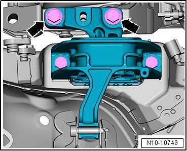
– First screw in bolts -arrows- for support arm of engine mount‐ing as far as stop by hand.
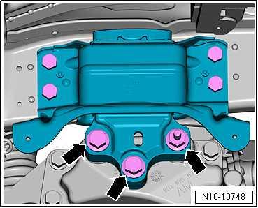
Vehicles with 3 gearbox securing bolts: – Unscrew gearbox mounting bolts -arrows- one after the other, and renew them (if not already renewed when installing en‐gine).
Protected by copyright. Copying for private or commercial purposes, in part or in whole, is not permitted unless authorised by SEAT S.A. SEAT S.A does not guarantee or accept any liability with respect to the correctness of information in this document. Copyright by SEAT S.A.
Vehicles with two gearbox securing bolts: – Unscrew gearbox mounting bolts -arrows- one after the other, and renew them (if not already renewed when installing en‐gine). Continued for all vehicles:
– Remove engine bracket - T10483- from engine. – Install starter ⇒ Electrical system; Rep. gr. 27 ; Starter; As‐sembly overview - starter . – Bleed clutch mechanism ⇒ Rep. gr. 30 ; Clutch mechanism; Bleeding clutch mechanism . – Install cables with cable support bracket or selector lever cable ⇒ Rep. gr. 34 ; Selector mechanism; Assembly overview selector cables .
– Install catalytic converter ⇒ “2.2.1 Catalytic converter - removing and installing, Leon 2013, Ibiza 2018, Arona”, page 459 . – Install drive shafts ⇒ Running gear, axles, steering; Rep. gr. 40 ; Drive shaft; Assembly overview - drive shaft . – Install pendulum support ⇒ “2.4.1 Removing and positioning pendulum support, Ateca, Leon 2013”, page 84 . – Protected by copyright. Copying for private or commercial purposes, in part or in whole, is not Install transverse link, swivel joint and coupling rod ⇒ Running permitted unless authorised by SEAT S.A. SEAT S.A does not guarantee or accept any liability with gear, axles, steering; Rep. gr. 40 ; Lower transverse link, respect to the correctness of information in this document. Copyright by SEAT S.A. swivel joint; Exploded view - lower transverse link, swivel joint . – Install air conditioner compressor ⇒ Heating, air conditioning; Rep. gr. 87 ; Air conditioner compressor; Assembly overview - drive unit of air conditioner compressor . – Install poly V-belt ⇒ “1.2.2 Removing and installing poly V-belt, vehicles with air conditioner compressor”, page 114 . – Install radiator cowl ⇒ “4.5.1 Removing and positioning the radiator cowl, Ateca, Leon 2013”, page 335 . – Electrical connections and routing ⇒ Electrical system; Rep. gr. 97 ; Relay carriers, fuse carriers, electronics boxes; Over‐view of fitting locations - relay carriers, fuse carriers, electron‐ics boxes ⇒ Current flow diagrams, Electrical fault finding and Fitting locations. – Install battery tray. ⇒ Electrical system; Rep. gr. 27 ; Battery; Removing and installing battery tray – Observe required procedures after connecting battery ⇒ Elec‐trical system; Rep. gr. 27 ; Disconnecting and reconnecting battery. – Install throttle valve module - J338⇒ “4.3 Removing and installing throttle valve module GX3 ”, page 402 . – Install engine control unit - J623⇒ “6 Engine (motor) control unit”, page 412 .
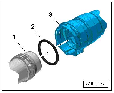
– Remove old O-ring -2- in coolant hose -3-. – Moisten new O-ring with coolant and insert into coolant hose. – Install wheel housing liners ⇒ General body repairs, exterior; Rep. gr. 66 ; Wheel housing; assembly overview - front wheel housing liner . – Position front wheels.
– Install air filter housing ⇒ “3.2 Removing and installing air filter housing”, page 397 . Checking engine oil level ⇒ “1.2 Engine oil:”, page 237
Note
♦ Never use battery charging equipment for boost starting. ♦ Risk of damage to control units caused by overvoltage.
Note
Protected by copyright. Copying for private or commercial purposes, in part or in whole, is not permitted unless authorised by SEAT S.A. SEAT S.A does not guarantee or accept any liability with respect to the correctness of information in this document. Copyright by SEAT S.A.
Do not reuse the dirty coolant.
– Add coolant ⇒ page 262 . • After renewing engine, the function “Misfiring adaptation” must be performed.
– To do this, select 01 - Reset misfiring adaptation on ⇒ Vehicle diagnostic tester in Guided functions mode.
Specified torques
Note
♦ The specified torques are only valid for nuts and bolts which have been slightly greased, oiled, phosphate-treated or blackoxided.
♦ Additional lubricant such as engine oil or gear oil may be used, but do not use lubricant containing graphite. ♦ Do not use degreased parts. ♦ Tolerance for specified torques ± 15%.
Component
Bolts and nuts Nm.
M6
M7 9
15
M8 20 M10 40 M12 65
♦ Assembly mountings ⇒ “2.1.1 Assembly overview - assembly mountings, Ateca, Leon 2013”, page 67 ♦ Securing gearbox to engine ⇒ Rep. gr. 34 ; Removing and installing gearbox; Specified torques for gearbox .
Component
Securing bolt for securing vacuum pump to engine support
Securing bolts for heat shield of knock sensor 1 - G61Specified torque
20 Nm
12 Nm
1.4.2 Installing engine, Ibiza 2018, Arona
Special tools and workshop equipment required ♦ Engine and gearbox jack - VAS 6931-
♦ Hose clip pliers - VAS 6362-
Protected by copyright. Copying for private or commercial purposes, in part or in whole, is not permitted unless authorised by SEAT S.A. SEAT S.A does not guarantee or accept any liability with respect to the correctness of information in this document. Copyright by SEAT S.A.
♦ Engine support - T10483-
♦ Torque wrench - V.A.G 1332-
♦ Torque wrench - V.A.G 1331-
Procedure
Note
♦ If a further tightening angle is specified for certain bolts, these must be renewed.
♦ Renew self-locking nuts and bolts, and seals, O-rings and gaskets. ♦ Secure all hose connections with the correct type of hose clips (same as original equipment) ⇒ Electronic parts catalogue . ♦ Fit heat shield sleeves in the same place when installing.
Protected by copyright. Copying for private or commercial purposes, in part or in whole, is not permitted unless authorised by SEAT S.A. SEAT S.A does not guarantee or accept any liability with respect to the correctness of information in this document. Copyright by SEAT S.A.
Procedure
– Installing intermediate plate ⇒ Fig. ““Installing intermediate plate”“ , page 136 – Clean input shaft splines and apply thin coat of grease for clutch plate splines . – Check centring of clutch plate. – Securely bolt gearbox to engine ⇒ Rep. gr. 34 ; Removing and installing gearbox; Installing gearbox .
Vehicles with manual gearbox – If there are no dowel sleeves -A- in the cylinder block for cen‐tring the engine and gearbox, insert new dowel sleeves.
Vehicles with dual clutch gearbox: – If there are no dowel sleeves -A- in the cylinder block for cen‐tring the engine and gearbox, insert new dowel sleeves. – If no needle bearing is fitted in crankshaft, install needle bear‐ing ⇒ “3.2 Renewing needle bearing in crankshaft”, page 145 . Continued for all vehicles
– Securely bolt gearbox to engine ⇒ Rep. gr. 34 ; Removing and installing gearbox; Installing gearbox . – Install gearbox support ⇒ “1.5.1 Engine support- removing and installing, Leon 2013, Ibiza 2018, Arona”, page 122 . – Take up engine/gearbox assembly with engine support T10483 .
– Guide engine/gearbox assembly into body.
– First screw in bolts -arrows- for support arm of engine mount‐ing as far as stop by hand.
Vehicles with 3 gearbox securing bolts: – Unscrew gearbox mounting bolts -arrows- one after the other, and renew them (if not already renewed when installing en‐gine).
Protected by copyright. Copying for private or commercial purposes, in part or in whole, is not permitted unless authorised by SEAT S.A. SEAT S.A does not guarantee or accept any liability with respect to the correctness of information in this document. Copyright by SEAT S.A.
Vehicles with two gearbox securing bolts: – Unscrew gearbox mounting bolts -arrows- one after the other, and renew them (if not already renewed when installing en‐gine). – Remove engine bracket - T10483- from engine. Vehicles with air conditioner compressor – Install air conditioner compressor ⇒ Heating, air conditioning; Rep. gr. 87 ; Air conditioner compressor; Assembly overview - drive unit of air conditioner compressor . – Install poly V-belt ⇒ “1.2.2 Removing and installing poly V-belt, vehicles with air conditioner compressor”, page 114 .
Continued for all vehicles
– Mount bracket for catalytic converter and tighten the bolts -arrows⇒ Fig. ““Installing catalytic converter - specified torque and tightening sequence”“ , page 456 . Protected by copyright. Copying for private or commercial purposes, in part or in whole, is not permitted unless authorised by SEAT S.A. SEAT S.A does not guarantee or accept any liability with – Install catalytic converter respect to the correctness of information in this document. Copyright by SEAT S.A. ⇒ “2.2.1 Catalytic converter - removing and installing, Leon 2013, Ibiza 2018, Arona”, page 459 . – Install drive shafts ⇒ Running gear, axles, steering; Rep. gr. 40 ; Drive shaft; Removing and installing drive shaft . – Install pendulum support ⇒ “2.4.2 Removing and installing pendulum support, Ibiza 2018, Arona”, page 85 . – Install front wheels ⇒ Running gear, axles, steering; Rep. gr. 44 ; Wheels, tyres, wheel alignment, wheel change . – Install starter ⇒ Electrical system; Rep. gr. 27 ; Starter; As‐sembly overview - starter . – Install clutch slave cylinder ⇒ Rep. gr. 30 ; Clutch mechanism; Removing and installing clutch slave cylinder . – Install switch actuation: ⇒ Rep. gr. 34 ; Switch actuation; Ex‐ploded view - cables . – Adjusting assembly mountings ⇒ “2.6 Assembly mountings - adjusting, Ateca, Leon 2013, Ibiza 2018, Arona”, page 106 . – Install radiator cowl ⇒ “4.5.2 Removing and positioning the radiator cowl, Arona, Ibiza 2018”, page 336 .


