1•14
Every 6000 miles or 6 months
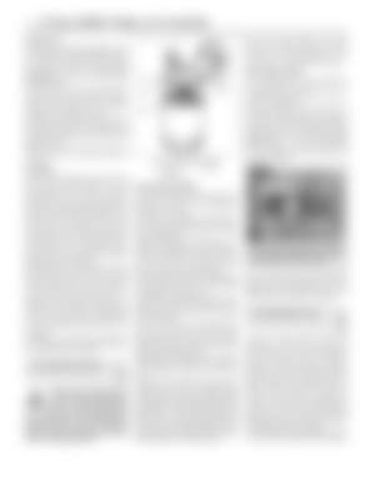
Canister type 16 Reposition the draining container under the oil filter then, using a suitable filter removal tool if necessary, slacken the canister initially, then unscrew it by hand the rest of the way; be prepared for some oil spillage (see illustration). Empty the oil in the old canister into the container. 17 Using a clean, lint-free rag, wipe clean the cylinder block around the filter housing. Check the old canister to make sure that the rubber sealing ring hasn’t stuck to the filter housing; if it has, carefully remove it. 18 Apply a light coating of clean engine oil to the sealing ring on the new canister. Screw the canister into position on the housing until it seats, then tighten it firmly by hand only - do not use any tools. 19 Remove the old oil and all tools from under the vehicle, then lower the vehicle to the ground.
Oil filling 20 Remove the dipstick and the oil filler cap from the engine. Fill the engine with oil, using the correct grade and type of oil, (see Specifications). Pour in half the specified quantity of oil first, then wait a few minutes for the oil to fall to the transmission casing. Take care during this operation, particularly in cold weather as it is all to easy to fill up the rocker cover before the oil drains down into the engine, with very messy results as it overflows out of the filler neck. Continue adding oil a small quantity at a time, until the level is up to the lower mark on the dipstick. Adding approximately 0.5 litres will raise the level to the upper mark on the dipstick. 21 Start the engine. The oil pressure warning light will take a few seconds to go out while the new filter fills with oil; do not race the engine while the light is on. Run the engine for a few minutes, while checking for leaks around the oil filter seal and the drain plug. 22 Switch off the engine, and wait a few minutes for the oil to settle in the transmission once more. With the new oil circulated and the filter now completely full, recheck the level on the dipstick, and add more oil as necessary. 23 Dispose of the used engine oil safely and in accordance with environmental regulations (see “General repair procedures”).
14 Front brake wear check
1
Warning: The dust created by wear of the shoes may contain asbestos, which is a health hazard. Never blow it out with compressed air, and don’t inhale any of it. An approved filtering mask should be worn when working on the brakes. DO NOT use petrol or petroleumbased solvents to clean brake parts; use brake cleaner or methylated spirit only.
10 Also check the condition of the brake drum, If it is deeply scored on its inner circumference it may be possible to have it skimmed at an engineering works. If the scoring is severe, renewal will be necessary
Disc brake models
13.16 Canister type oil filter 1 Housing 2 Sealing ring
11 Jack up the front or rear of the vehicle in turn, and support it on axle stands (see “Jacking and vehicle support”). 12 For better access to the brake calipers, remove the roadwheels. 13 Look through the opening in the front of the caliper, and check that the thickness of the friction lining material on each of the pads is not less than the recommended minimum thickness given in the Specifications (see Haynes Hint). If any one of the brake pads has worn down to, or below, the specified limit, all four pads must be renewed as a set (ie all the front pads).
3 Filter
Drum brake models 1 After high mileage the friction linings on the brake shoes will have worn, and it will therefore be necessary to fit replacement shoes with new linings. 2 Chock the rear wheels then jack up the front of the car and support it on axle stands (see “Jacking and vehicle support”). Remove the front roadwheels. 3 Slacken off the brake shoe adjuster(s) from behind the backplate, and then undo and remove the two brake drum retaining screws. 4 Remove the brake drum from the wheel hub. If the drum is tight, gently tap its circumference with a soft-faced mallet. 5 Brush and wipe away all traces of asbestos dust from the brake shoes, wheel cylinders and backplate, and also from the inner circumference of the brake drum. 6 Inspect the friction material and renew the brake shoes as described in Chapter 9 if they have worn down to less than the specified minimum thickness. 7 The brake shoes must also be renewed if there is any sign of hydraulic fluid contamination of the linings due to a leaking brake wheel cylinder. If this is the case, the cause of the leak must be traced and rectified before fitting new brake shoes. 8 Brake shoes should always be renewed as complete sets (four shoes to a set), otherwise uneven braking and pulling to one side may occur. 9 It is advisable to check that the brake wheel cylinders are operating correctly before proceeding further. To do this hold the brake shoes in position using two screwdrivers while an assistant very slowly depresses the brake pedal slightly. Check that the wheel cylinder pistons move out as the pedal is depressed, and return when the pedal is released. If this is not the case, it is quite likely that one of the wheel cylinder pistons is seized and the cylinder should therefore be renewed (Chapter 9).
Look through the opening in the caliper and check the thickness of the friction lining material on the brake pads 14 For a comprehensive check, the brake pads should be removed and cleaned. The operation of the brake calipers can then be checked, and the brake discs can be fully examined. Refer to Chapter 9 for details.
15 Driveshaft gaiter check
1
With the vehicle raised and securely supported on stands (see “Jacking and vehicle support”), turn the steering onto full lock, then slowly rotate the roadwheel. Inspect the condition of the outer constant velocity (CV) joint rubber gaiters, squeezing the gaiters to open out the folds. Check for signs of cracking, splits or deterioration of the rubber, which may allow the grease to escape, and lead to water and grit entry into the joint. Also check the security and condition of the retaining clips. Repeat these checks on the inner CV joints where offset sphere type joints are fitted. If any damage or deterioration is found, the gaiters should be renewed as described in Chapter 8. At the same time, check the general condition of the CV joints themselves by first holding the


