3 minute read
Check the emission control equipment (Section


12.25 Removing the engine upper tie-bar from the cylinder block 12.30 Lower engine tie-bar attachments
22 Undo and remove the two nuts, bolt and spring washers securing the mounting to the subframe. 23 Raise the jack slightly and remove the bolts securing the mounting to the bracket on the transmission casing. The engine mounting can now be withdrawn. 24 Refitting is the reverse sequence to removal. Upper tie-bar and bushes renewal
25 Undo and remove the two bolts securing the tie-bar and mounting bracket to the righthand side of the engine (see illustration). Move the tie-bar sideways and recover any spacing washers that may be fitted. 26 If the tie-bar is secured to its mounting bracket on the bulkhead by a through-bolt and locknut, remove the locknut and bolt and lift away the tie-bar. 27 If the tie-bar is secured by a stud with nuts and spring washers at each end, undo and remove the nuts and spring washers, then slacken the four nuts securing the clutch and brake master cylinder to the bulkhead. When sufficient clearance exists, lift up the tie-bar upper mounting bracket over the tie-bar stud, and withdraw the tie-bar. 28 With the tie-bar removed, slide out the rubber bushes and spacers and, if there is any sign of swelling or deterioration of the rubber whatsoever, renew the bushes. 29 Refitting is the reverse sequence to removal. Lower tie-bar and bushes renewal
30 The lower tie-bar fitted to later models may be mounted in one of two positions; either bolted to a bracket on the left-hand side of the transmission at one end and to the rear of the subframe at the other, or bolted to a bracket on the right-hand side of the transmission at one end and to the front of the subframe at the other. The renewal procedure is the same for both types (see illustration). 31 Chock the rear wheels then jack up the front of the car and support it on axle stands (see “Jacking and vehicle support”). 32 Undo and remove the bolts securing the tie-bar to the transmission bracket and subframe, and withdraw the tie-bar. 33 To remove the bushes it will be necessary to draw them out using a tube of suitable diameter, a long bolt and nut, and packing washers. The new bushes are refitted in the same way but lubricate them with liquid detergent before fitting. 34 Refitting is the reverse sequence to removal.
13 Distributor driveshaft removal and refitting - 1 Removal
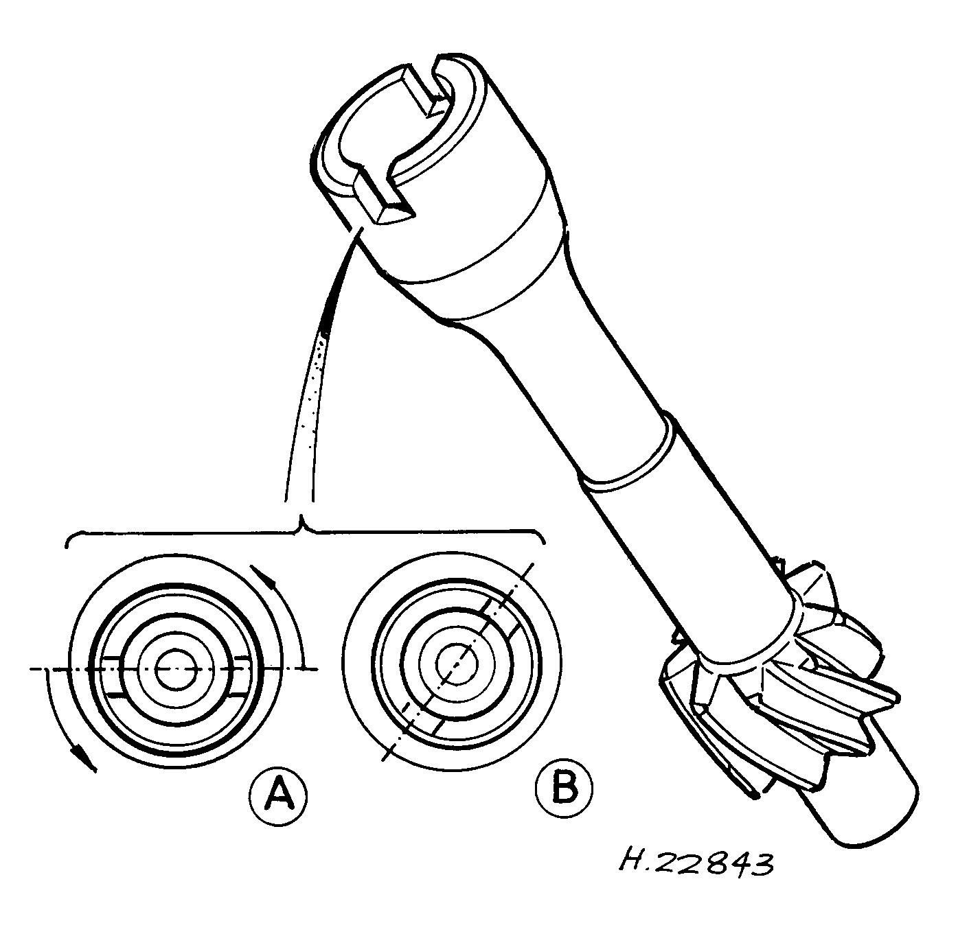
1 Set the engine with No 1 cylinder at TDC on compression as described in Section 3. 2 Remove the distributor as described in Chapter 5B. 3 Where a distributor base housing is fitted to the cylinder block, unscrew the single retaining bolt and lockwasher and remove the housing. 4 Look down into the distributor aperture and observe the position of the slot in the distributor driveshaft. With No 1 piston at TDC, the slot should be positioned as shown according to engine type (carburettor engines or fuel injection engines) (see illustrations).
13.4a Distributor driveshaft components and fitting details carburettor engines Inset A shows the position of the slot ready for fitting Inset B shows the shaft correctly installed 1 Driveshaft 2 Housing 3 Retaining screw 4 5⁄16 in UNF bolt (for removal and refitting of driveshaft) 13.4b Distributor driveshaft fitting details - fuel-injection models
A Drive slot position prior to engagement with skew gear B Correct drive slot position with shaft correctly installed