4 minute read
renew if necessary (Section


Inspect the fittings for cracks, and check the hose where it fits over the fitting for distortion, which could cause leakage. 9 A small piece of vacuum hose can be used as a stethoscope to detect vacuum leaks. Hold one end of the hose to your ear, and probe around vacuum hoses and fittings, listening for the “hissing” sound characteristic of a vacuum leak. Warning: When probing with the vacuum hose stethoscope, be very careful not to come into contact with moving engine components such as the fan or fan belt. Fuel hoses
Warning: Before carrying out the following operation, refer to the precautions given in “Safety first!” at the beginning of this manual, and follow them implicitly. Petrol is a highly dangerous and volatile liquid, and the precautions necessary when handling it cannot be overstressed. 10 Check all fuel hoses for deterioration and chafing. Check especially for cracks in areas where the hose bends, and also just before fittings, such as where a hose attaches to the carburettor. 11 Spring-type clamps are commonly used on fuel lines. These clamps often lose their tension over a period of time, and can be “sprung” during removal. Replace all springtype clamps with screw clips whenever a hose is replaced. Metal lines
12 Sections of metal piping are often used for fuel line between the fuel tank, filter and the engine. Check carefully to be sure the piping has not been bent or crimped, and that cracks have not started in the line. 13 If a section of metal fuel line must be renewed, only seamless steel piping should be used, since copper and aluminium piping don’t have the strength necessary to withstand normal engine vibration. 14 Check the metal brake lines where they enter the master cylinder for cracks in the lines or loose fittings. Any sign of brake fluid leakage calls for an immediate and thorough inspection of the brake system.
19 Fuel system components, checks and lubrication 1
1 Sparingly apply a few drops of light oil to the throttle spindles, accelerator cable and the pedal pivot. Similarly lubricate the exposed ends of the choke cable (where fitted). 2 Check that there is a small amount of slackness in the cable so that the throttle linkage closes fully with the accelerator pedal released. Also check that full throttle can be obtained with the accelerator pedal fully depressed. 3 If there is any doubt about the cable adjustment, refer to the relevant Parts of Chapter 4 for the full adjustment procedure. 4 On carburettor models, unscrew the piston damper cap from the top of the carburettor dashpot (see illustration). Top up the damper with engine oil until the level is 13.0 mm above the top of the hollow piston rod. 5 Slowly push the damper back into the piston and screw on the cap taking care not to cross-thread it.
20 Contact breaker points check and adjustment 3
Refer to Chapter 5B.
21 Distributor lubrication 1
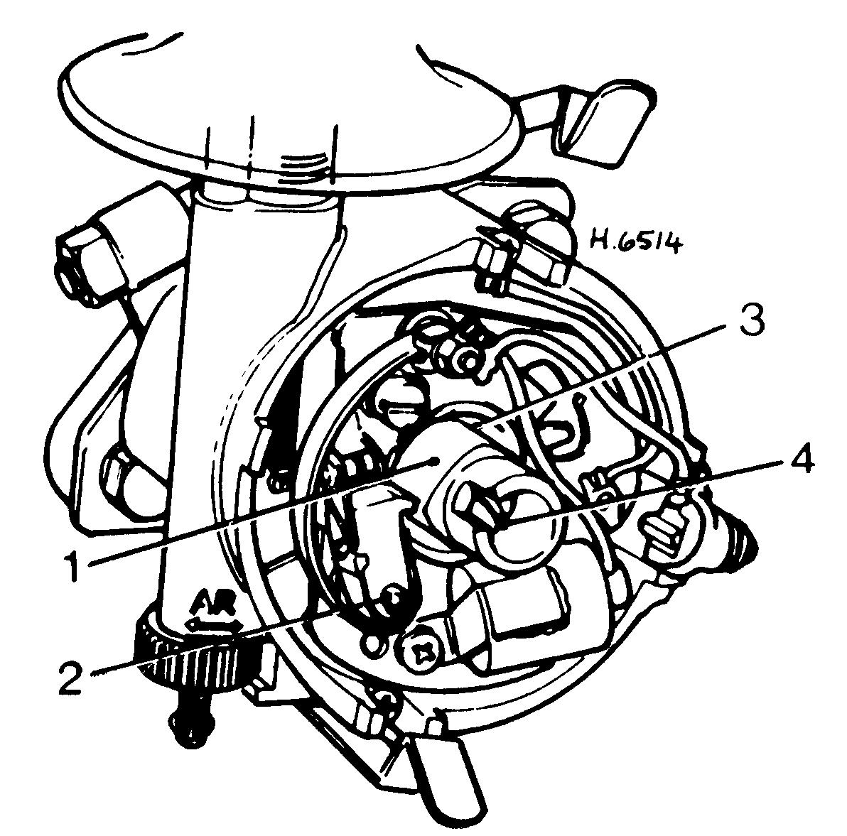
1 It is important that the distributor cam is lightly lubricated with general purpose grease, and that the contact breaker arm, centrifugal advance weights and cam spindle are also very lightly lubricated. 2 Great care should be taken not to use too much lubricant, as any excess that might find its way onto the contact breaker points could cause burning and misfiring. 3 If an ignition shield is fitted over the front of the engine, release the three plastic retaining lugs and lift away the shield. Detach the two spring clips or undo the two screws securing the distributor cap to the distributor body and lift off the cap. 4 To gain access to the cam spindle, lift away the rotor arm. Drop no more than two drops of engine oil onto the felt pad or screw head (see illustration). This will run down the spindle when the engine is hot and lubricate the bearings. The centrifugal advance weights can be lubricated by dropping two or three drops of engine oil through one of the holes or slots in the distributor baseplate. No more than one drop of oil should be applied to the contact breaker arm pivot post. 5 Refit the rotor arm, distributor cap and ignition shield on completion.
19.4 Top up the piston damper on carburettor models
22 Clutch return stop adjustment 1
Note: As friction linings of the clutch disc wear, the distance between the clutch release bearing and the clutch thrust plate will decrease. The pressure plate will then move in closer to the clutch disc to compensate for wear. Unless the wear is taken up by adjustment of the stop located between the flywheel housing and the
21.4 Distributor lubrication points 1 Contact breaker cam 2 Contact breaker pivot post 3 Centrifugal weights lubrication point 4 Cam spindle