3 minute read
paintwork (Section


5.22a Timing dots on sprockets aligned with chain fitted
the sprockets back into mesh with the chain so that the timing dots, although further apart are still adjacent to each other (see illustrations). 23 Check that the engine is still positioned at TDC for No 1 piston (Section 3). In this position the crankshaft Woodruff key should be at the 12 o’clock position and the camshaft Woodruff key should be at the 2 o’clock position. 24 Fit the timing chain and sprocket assembly onto the camshaft and crankshaft, keeping the timing marks adjacent. If the camshaft and crankshaft have been positioned accurately, it will be found that the keyways on the sprockets will match the position of the keys, although it may be necessary to rotate the camshaft a fraction to ensure accurate liningup of the camshaft sprocket. 25 Press the sprockets into position on the crankshaft and camshaft as far as they will go. Note: If new sprockets are being fitted they should be checked for alignment before being finally fitted to the engine. Place the sprockets in position without the timing chain and place the straight edge of a steel ruler from the side of the camshaft gear teeth to the crankshaft sprocket and measure the gap between the steel rule and the sprocket (see illustration). If a gap exists a suitable number of packing washers must be placed on the crankshaft nose to bring the crankshaft sprocket onto the same plane as the camshaft sprocket. 26 Fit the oil thrower to the crankshaft with the concave side forward. 27 Fit the locking washer to the camshaft sprocket with its locating tab in the sprocket keyway. 28 Screw on the camshaft sprocket retaining nut and tighten securely. 29 Bend up the locking tab of the locking washer to hold the camshaft retaining nut securely. 30 On engines with a separate timing chain tensioner, refit the tensioner and retaining bolt ensuring that there is a washer on each side of the tensioner arm. 31 Generously oil the chain and sprockets. 32 Apply a bead of RTV sealant to each side of the new gasket, on the lower half of the gasket only. Place the gasket on the timing cover then quickly position the timing cover on the engine. 33 Screw in the timing cover retaining bolts with the flat washer next to the cover flange and under the spring washer. Tighten the respective bolts to the specified torque. 34 Fit the crankshaft pulley to the nose of the crankshaft, ensuring that the keyway engages with the Woodruff key. 35 Fit the crankshaft retaining bolt locking washer and screw in the crankshaft pulley retaining bolt. Tighten to the specified torque while using the same method to prevent crankshaft rotation as was used for removal. 36 Where removed, refit the radiator lower mounting bracket and secure the bracket to the engine/transmission and subframe. Remove the jack under the engine. 37 Refit the fan to the water pump spindle and secure with the four bolts securely tightened. 38 Refit the radiator as described in Chapter 3 and the fan belt as described in Chapter 1. 39 Refit the components removed when setting the engine at TDC, then reconnect the battery.
6 Rocker shaft assembly removal, inspection and refitting 3
General information
1 The rocker shaft assembly is secured to the top of the cylinder head by the cylinder head inner studs and nuts. Although in theory it is possible to undo the head nuts and remove the rocker shaft assembly without removing the head, in practice, this is not recommended.
5.22b Timing mark locations relative to keyways 1 Timing dot on camshaft sprocket 2 Timing dot on crankshaft sprocket
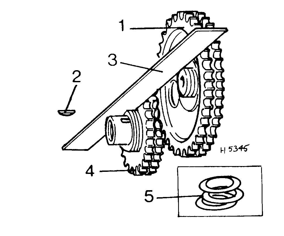
5.25 Timing sprocket alignment - double row type shown 1 Camshaft sprocket 2 Woodruff key 3 Straight edge 4 Crankshaft sprocket 5 Inset: shims
Note that with single row type, it is important to align the sides of the teeth and not the raised hub of the sprocket