CONTACT INFO
MANAGING EDITOR
James Little james.little@palladianpublications.com
EDITORIAL ASSISTANT
Sara Simper sara.simper@palladianpublications.com
SALES DIRECTOR

Rod Hardy rod.hardy@palladianpublications.com
SALES MANAGER
Chris Lethbridge chris.lethbridge@palladianpublications.com
SALES EXECUTIVE
Daniel Farr daniel.farr@palladianpublications.com
PRODUCTION MANAGER
Calli Fabian calli.fabian@palladianpublications.com
EVENTS MANAGER
Louise Cameron louise.cameron@palladianpublications.com
DIGITAL EVENTS COORDINATOR
Stirling Viljoen stirling.viljoen@palladianpublications.com
DIGITAL CONTENT ASSISTANT
Merili Jurivete merili.jurivete@palladianpublications.com
DIGITAL ADMINISTRATOR
Leah Jones leah.jones@palladianpublications.com
ADMINISTRATION MANAGER
Laura White laura.white@palladianpublications.com
Palladian Publications Ltd, 15 South Street, Farnham, Surrey, GU9 7QU, UK
Tel: +44 (0) 1252 718 999 Website: www.worldpipelines.com Email: enquiries@worldpipelines.com
Annual subscription £60 UK including postage/£75 overseas (postage airmail). Special two year discounted rate: £96 UK including postage/£120 overseas (postage airmail). Claims for non receipt of issues must be made within three months of publication of the issue or they will not be honoured without charge.
Applicable only to USA & Canada: World Pipelines (ISSN No: 1472-7390, USPS No: 020-988) is published monthly by Palladian Publications Ltd, GBR and distributed in the USA by Asendia USA, 17B S Middlesex Ave, Monroe NJ 08831. Periodicals postage paid New Brunswick, NJ and additional mailing offices. POSTMASTER: send address changes to World Pipelines, 701C Ashland Ave, Folcroft PA 19032
The security of critical infrastructure is always at the forefront of national and international agendas, but there are times when we feel more vulnerable than others: times when we feel that an attack is more likely, or could be more damaging if it does happen.
Russia’s aggressions against Ukraine have undoubtedly highlighted the weak points inherent in modern global connectivity.
At the end of September, three of the four Nord Stream gas pipelines were damaged beyond repair, ruptured by what experts believe were large explosions in the Baltic Sea. It’s unclear who attacked the subsea pipelines, but the act of sabotage draws the world’s attention to the vulnerabilities we already knew existed in pipelines. Since then, several nations have elevated their surveillance efforts to monitor the security of maritime infrastructure. Gassco ordered the deployment of a vessel with ROVs to survey the Europipe II pipeline; the UK is planning to buy two special-purpose ships to survey and defend against subsea threats, and the Italian Navy has dispatched ships to monitor gas pipelines in the Mediterranean.
Recent reports from the Isles of Shetland, off the coast of Scotland, described subsea cable damage that left the islands cut off from the mainland. Police declared a major incident after the subsea cable between the islands and the mainland was cut. Phone, broadband and mobile (cell) services were affected, which had a knockon effect for emergency services and ATMs, among other things. Fishing trawlers have been blamed for the damage, and the incident highlighted the fragility of subsea connections.
In April 2021, monitors at the Norwegian Institute of Marine Research went blank as a 4.2 km subsea cable in the Arctic Ocean stopped transmitting data to its host country. The fibre optic cable lines measured environmental conditions and fish migration, recording images and sound, and delivered data back to Norway. In November 2021, a 3 km section of the severed cable was found drifting at sea, some 11 km out of position. AIS vessel tracking data showed a Russian trawler had crossed over the cable at the time when the ocean researchers received its last signal. When retrieved, the cable appeared to have been cut by a power tool.
Within the last couple of weeks, France has tightened security on its subsea cables amid concern they might be a target for an attack. According to Politico, “the French presidency has been consulting with leading experts, including senior civil servants and naval officials, to work out how to better protect underwater cables and prevent an unprecedented attack on Europe’s internet.”1 France is investing in high-tech equipment to protect critical infrastructures: its 2023 budget, which is currently being debated in parliament, includes €3.1 million for ocean floor defence, accounting for the protection of natural resources and undersea cables.
In this special ‘Coatings & Corrosion’ issue of World Pipelines, we look at the various points of vulnerability for the industry, analysing where and when damage might occur to pipelines and outlining how to evaluate, repair and, ultimately, avoid damage and degradation. Read on for articles about: the use of satellitederived data in decision-making for crisis events; protecting those coatings in the ground; thermal insulation for subsea pipelines; and more.
1. www.politico.eu/article/france-tighten-subsea-cable-security-fear-sabotage-pipeline-gas-leak
SENIOR EDITOR Elizabeth Corner elizabeth.corner@palladianpublications.com
Hall, Senior Specialist on Earth Observation Applications, Airbus Defence and Space, UK, explains how satellite-derived data is enhancing decision-making across the oil and gas value chain.
il and gas producers are increasingly turning to satellite-derived data provided by aerospace companies like Airbus Defence and Space to aid exploration, target development and protect assets in remote locations.
Admittedly, the hydrocarbons and aerospace sectors might not seem like a match made in heaven. After all, the first is primarily concerned with what is going on deep underground, while the second has its head in the clouds (metaphorically, of course). What unites them, however, is decades of experience closely studying the Earth’s surface – although from very different vantage points.
Current geopolitical turbulence, combined with technological developments that have unlocked hard-to-reach oil and gas deposits, means there is more need than ever for accurate, reliable geospatial insight. This is precisely what satellite data offers.
Satellites have an enormous range of applications, but in relation to earth observation, they are increasingly being used to capture and deliver high-resolution imagery in near real-time.

Satellite imagery can be studied independently or crossreferenced with archived data to monitor the evolution of a landscape. Although the basic content of satellite imagery is obvious to the untrained eye (for example, we can all tell the difference between land and sea), highly trained expert analysts can assess the characteristics and context to reveal additional hidden insights across all stages of the oil and gas production lifecycle.
Satellite capabilities
Airbus satellites offer highly flexible acquisition capacities. They can cover any point on Earth at least once per day and have 24/7 availability. This ensures near-real-time data processing and delivery for time-critical requests.
) Pléiades Neo: Airbus’ most advanced optical constellation with four identical 30 cm resolution satellites and intra-daily revisit.
) Pléiades: Optical satellite constellation providing imagery at 50 cm resolution with a 20 km swath.
Michael
4
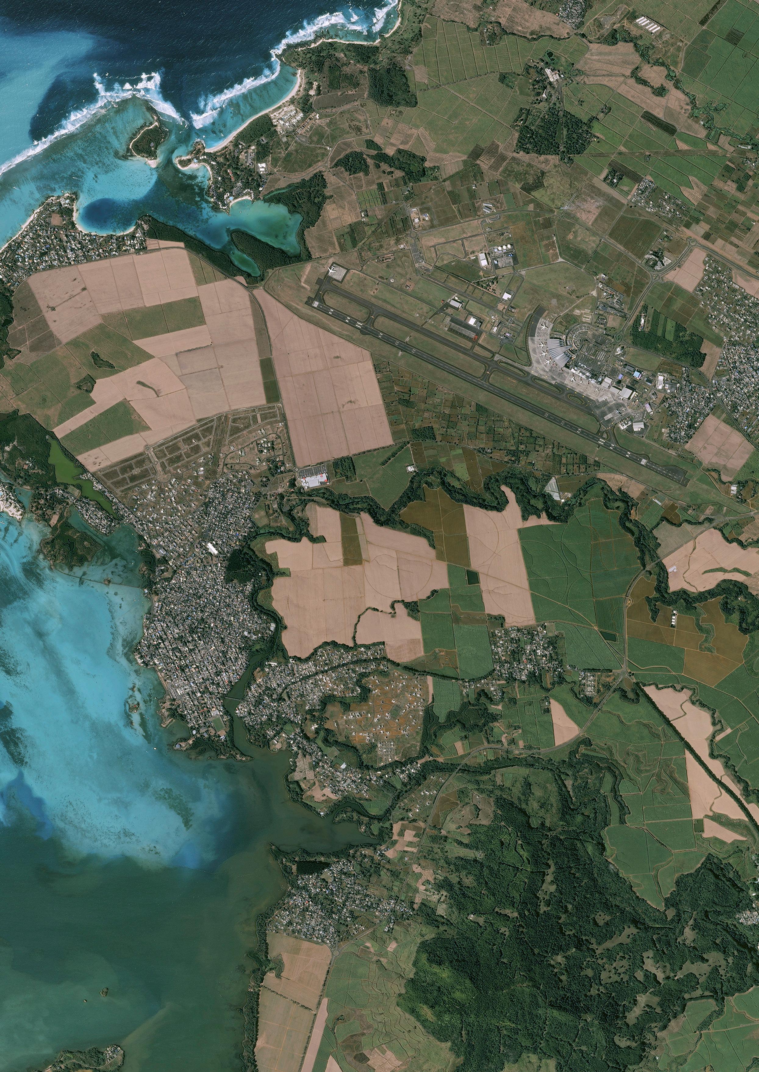
Figure 1. Pléiades – Mauritius oil spill.
5
) Vision-1: Optical satellite providing imagery at 90 cm resolution for mapping over large areas.
) SPOT: Optical satellites that can cover large areas in a single pass, at resolutions up to 1.5 m. Its precise coverage is ideal for applications at national and regional scales from 1:250 000 to 1:15 000.
) Radar constellation: These radar satellites can provide imagery with up to 25 cm resolution, regardless of weather conditions.
Simplifying feasibility
Oil and gas operations are increasingly moving into remote, hard-to-access locations. In these inhospitable environments, satellite-derived data can be invaluable in helping to find and evaluate new leads. It is often used alongside 2D and 3D seismic data, as well as other geo-science datasets, to develop a rounded geological understanding of a licence block.
In addition, satellite data is increasingly being used to assess ground conditions – terrain, geology and access – before field activity and seismic acquisition begin.
Enhancing exploration
With the energy transition in full swing, accurately validating and prioritising exploration opportunities is more important than
ever – particularly when it comes to offshore exploration, due to the high costs involved.
Using satellite radar data, oil and gas companies can spot the location of sea surface slicks associated with natural oil seeps from the seafloor, or oil pollution from ships or other manmade sources. To support this, Airbus has been steadily building the Global Seeps database for over two decades. New frontier basins can be assessed and added to the database. In addition, existing locations can be regularly reassessed. As the archive of imagery taken over a particular location grows, expert analysts can become increasingly confident in any natural slicks identified and differentiate from manmade oil pollution.
Furthermore, it can be helpful to compare the location of natural oil seeps with other geophysical data. For instance, the Earth Observation Applications team at Airbus worked with a seismic multi-client acquisition and imaging specialist to produce a study offshore Croatia, covering several blocks along the country’s Adriatic coast. The study correlated high confidence natural oil seeps identified from radar and optical satellites with structural features interpreted from 2D seismic data, allowing the targeting of further exploration work.
Informing development
Given the massive cost outlays involved in developing oil and gas assets, engineers must take every possible opportunity to minimise risks and avoid unwelcome surprises – both manmade and natural.
Let’s take the example of pipeline development. From a manmade perspective, risks might include cultural landmarks or potential security issues – including theft, vandalism or terrorist attack. On the other hand, natural risks include hurricanes, floods, fires, earthquakes and exposure to the elements – which can speed up the degradation of pipework and supporting structures.
Traditional methods of pipeline planning and monitoring can be either extremely time and resource intensive (in the case of ground-based data collection) or very expensive (in the case of airborne surveys). By contrast, satellite-based precision elevation models and mapping solutions offer rapid, wide-area information collection, complementing other methods. This enables companies to make fast, intelligence-driven planning decisions and ultimately define the best possible pipeline routes.
As an example, Airbus helped Austriabased ILF Consulting Engineers obtain up-todate data to calculate the optimum route for a portion of the South Caspian pipeline, located in Georgia and Azerbaijan.
To get the information they needed, the Airbus team started by using SPOTMaps (one of the Reference Layers, a seamlessly orthorectified mosaic derived from SPOT
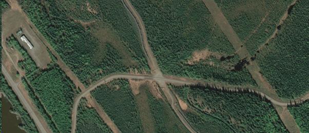
Figure 3. Pléiades image of pipeline in Alaska in an area with vegetation. Pléiades © CNES 2021, Distribution Airbus DS.
6 World Pipelines / COATINGS & CORROSION 2022
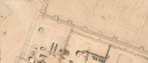
Figure 2. Pléiades image of pipeline and facilities in Saudi Arabia. Pléiades © CNES 2022, Distribution Airbus DS.



FIELD JOINT PROTECTION? WE’VE GOT THE SYSTEMS TO SUIT YOUR REQUIREMENTS BITUMEN & BUTYL TAPES VISCOELASTIC TAPES HEAT SHRINKABLE SLEEVES PETROLATUM TAPES, MASTICS & OUTERWRAPS PROTAL™ LIQUID EPOXY COATING FOR CORROSION PREVENTION DENSO™
corrosion prevention and sealing
United Kingdom, UAE & India USA & Canada Australia & New Zealand Republic of South Africa www.denso.net www.densona.com www.densoaustralia.com.au www.denso.co.za A MEMBER OF WINN & COALES INTERNATIONAL
are leaders in
technology. With over 135 year’s service to industry, our mainline and field joint coating solutions offer reliable and cost effective protection for buried pipelines worldwide.
satellite imagery) and Elevation30 data to support a preparatory study of the pipeline corridor. Next, they used Elevation1 (a digital terrain model derived from Pléiades and orthorectified mosaic) for detailed modelling to support final analysis and potential re-routing. This included extracting 3D vector maps for a subset of the corridor. Finally, ground control points (GCPs) were captured and used to increase absolute accuracy in plan and elevation.
When tested, the findings proved highly reliable. When the Pléiades derived elevation model was compared to highly precise in situ-measurements, over 80% of the evaluated area showed an accuracy of 50 - 60 cm in the vertical component, exceeding requested specifications.
Protecting pipelines
Monitoring remote oil and gas pipeline installations is a complex process. But it can be significantly simplified with the use of satellite data, which can help track operational activity, potential security risks, and any immediate environmental issues. Illegal pipeline tapping is a widespread phenomenon. Not only does it dent oil producers’ profits, but also presents significant human safety and environmental risks. Unfortunately, despite the best efforts of oil producers, many producing countries have seen an uptick in illegal tapping incidents in recent years. For example, due to industrial-scale tapping, Nigeria’s government lost an estimated US$1 billion in revenue during 1Q22, according to the Nigerian Upstream Petroleum Regulatory Commission.
In addition to deliberate illegal tapping, pipeline integrity is also at risk from accidental damage due to agriculture and unlicensed constructions. Whether damage is deliberate or accidental, satellite imagery can play a crucial role in identifying changes which indicate preparations for pipeline tapping or damage, as well as recognising oil impacted ground post-event – information that would be difficult to acquire using more traditional means.
To further enhance satellite-derived monitoring, Airbus has developed change detection algorithms and other machine learning techniques which will automatically identify changes or activity seen in high resolution satellite imagery associated with human activity. By reducing the need for expert analysis of imagery, oil and gas companies can receive insights even faster – enabling them to access market insights more rapidly. Change detection algorithms could be used for infrastructure development identification near a pipeline.
Controlling crises
No matter what measures companies put in place to enhance safety, oil and gas exploration and production carries inherent risks. When an accident, disaster or unexpected event happens, satellite-derived data enables companies to act quickly and contain the impact.
For example, in 2017, pirates captured the Aris 13 oil tanker and its eight crew members during its journey from Djibouti to Mogadishu. Once onboard, the pirates cut off all the communication and positioning equipment including the AIS emitter that regularly transmits the vessel’s identity, position and course. Airbus used the Pléiades satellites to find the vessel using its last AIS positions. Aris 13 was identified within days on specifically captured Pléiades image. Airbus is able to engage at speed and provide accurate and relevant data to be combined with other information sources to better protect in times of unexpected events.
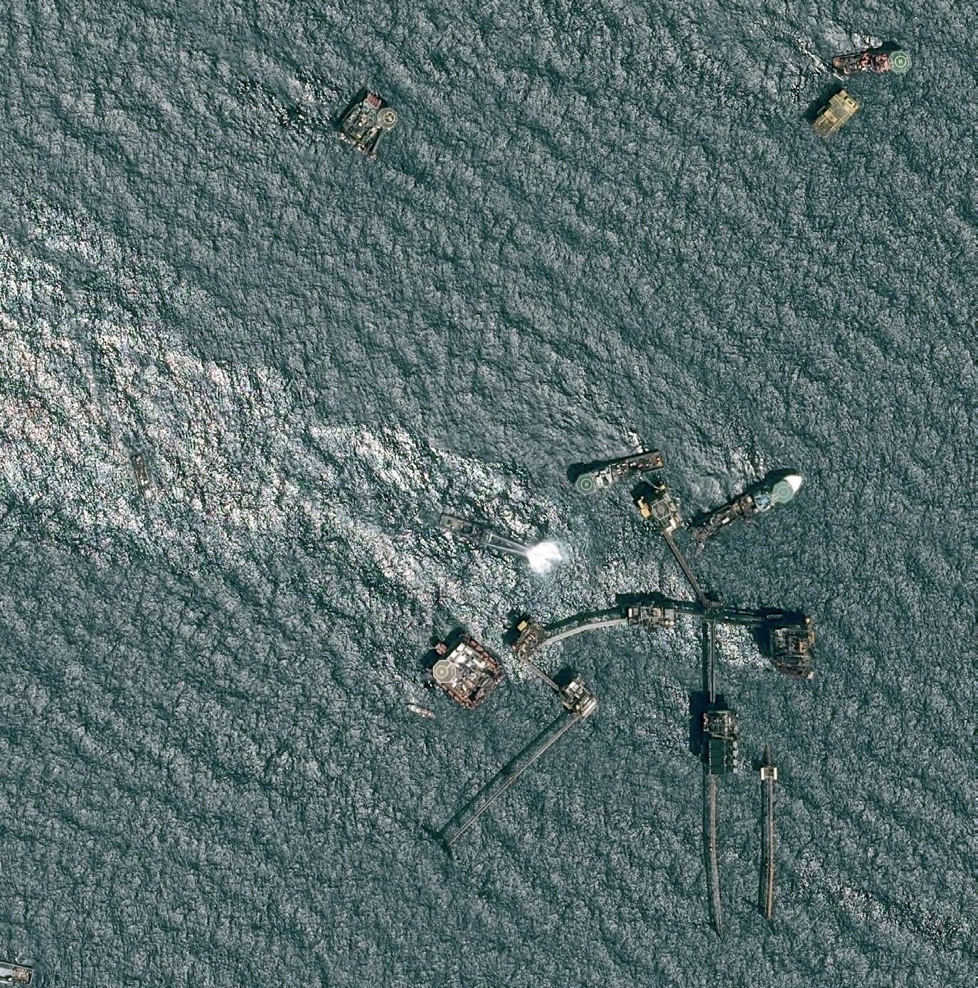
Oil spills are another serious disaster, the impact of which can include environmental damage, loss of revenue, clean-up costs and reputational harm. Again, satellite-derived imagery can play a key role in containing the fallout. For instance, Airbus played a role in tracking the events following the 2010 Deepwater Horizon oil spill in the Gulf of Mexico. Data gathered by Airbus satellites help spill response fleets tactically position booms, skimmers, dispersants, and support other clean-up activities.
It’s clear that both archive and freshly acquired highresolution satellite imagery is changing the way oil, gas, and engineering companies see the world. The ability to rapidly view up-to-date images taken from hundreds of kilometres above the Earth provides valuable knowledge across all stages of the production lifecycle.
8 World Pipelines / COATINGS & CORROSION 2022
Figure 4. Pléiades – oil rig explosion ‘Permanent Abkatun’, Gulf of Mexico.
Lifelong Safety is Everything.
100 years of innovation power. For safeguarding your pipeline. For protecting people and nature. denso-group.com

100 Years DENSO. Advanced in Sealing.

10
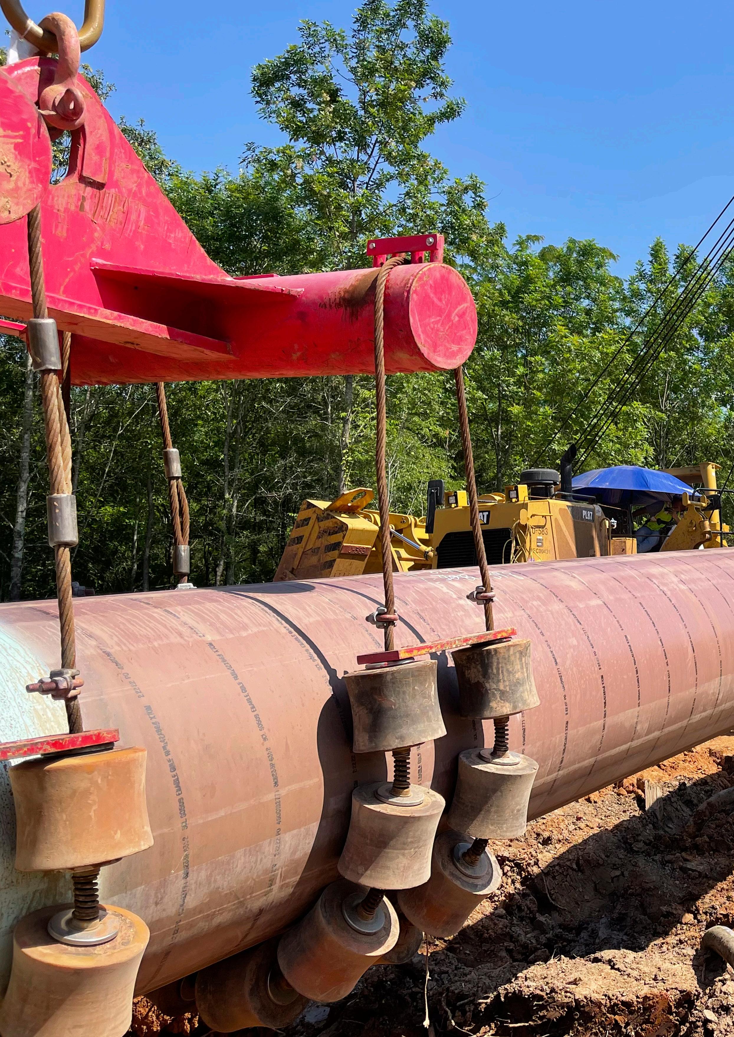
F igure 1. HDD pipe being laid in the ditch.
Doug Sinitiere, Carboline, and Will Hon, SPC, USA, discuss undertaking a large pipeline construction project amidst current global challenges.
s the global energy infrastructure continues to grow, so does the need for pipelines and the ‘spreads’ (the manageable lengths of a large pipeline construction project) that comprise them. Today’s pipeline projects are not just for creating additional transportation channels but also for converting existing assets for new feedstock support. However, the size and frequency of such projects can vary based on factors including market dynamics, changes in commodity pricing, regulatory policy, and measures taken to increase safety and reliability. Project numbers fluctuate yearly (see Figure 2 for recent numbers from the US), but one thing is certain; pipelines are still crucial for supplying global energy.
One project currently in the works in the US is an interstate natural gas transmission pipeline in the Gulf East – Energy Transfer’s Gulf Run Pipeline. This pipeline will support global markets by helping to provide access to key natural gas-producing regions of the US.
Naturally, when the pre-work and planning of this project started in 2018, the world was not experiencing shortages in raw materials, shipping and ground transportation backlogs, significant labour shortages, and commercial pressures, at least not to the extent faced today. Yet, despite these challenges, the project has continued, and it is still on track to fulfilling its mission; supplying energy to global markets that desperately need it, which is more important now than ever given today’s geopolitical climate.
“How has this project stayed on track?” one might ask. The answer, simple yet challenging to adhere to at times, is threefold:
) There was an early metallurgical and corrosion scenario review for material selection purposes.
) There has been involvement from supply chain, logistics, and estimating personnel.
) There have been heavy collaborative efforts between multiple parts of the contract chain, including the operator, general contractor, sub-contractor, etc.
Metallurgical and corrosion scenario
This project, like many others, necessitated completing a series of tasks before anyone could do any dirt work. The pipeline project required input from the public and government stakeholders along its proposed route. Additionally, with the Federal Energy Regulatory Commission (FERC) having regulatory oversight and approval for certain pipelines, the project specifications had references to best practices such as NACE No. 1, NACE SPO490, and API 5L. Each project evaluation considered industry, regulatory and environmental best practices to ensure compliance and success.
As projects evolve, there is always the ‘dance’ of supporting shop/offsite and site location activities. This dance may sound simple enough, but it represents differences that can affect how and when protective coatings are applied. For example, many shop applications involve environmental controls, automation, and other robust ways to complete coating applications, providing an optimum environment to prepare and apply the protective coating systems. It is a relatively simple and straightforward process. On the other hand, site work at the project’s location requires extra coordination for various reasons, including scheduling around other crafts and site works, consideration of any
11
surface preparation activities involving spent abrasives, application of coatings and wind directions, containments to be built, and access to power and water, among others.
The project team on the Gulf Run Pipeline used automated ring coatings for the girth welds, directional drills, and bore crossings, allowing them to prioritise the bulk of their coating manufacturing toward the 800 l. drum set spray coating. This strategy of organisation and prioritisation is essential to note as manufacturing spray-grade coatings is a more streamlined and less hands-on task. As a result, this strategic decision ultimately proved to be a critical element in sourcing the material effectively.
Coating projects occurring in the field, on the right of way, can require several applicators and introduce complexity. With the Gulf Run project consisting of bulk large diameter pipe (larger than 24 in.), spray ring application could save on waste, human resources, and disposal costs. However, these savings could only be possible with the proper machinery setup. As such, it is imperative to have an experienced applicator. Thankfully, Specialty Polymer Coatings (SPC) had good experiences working with the subcontractor in the past, including on several projects utilising their spray ring, so we knew the application for this project was in good hands.
All these factors are key and instrumental in ensuring the proper protection of the assets going into service, not only for the immediate project timeline but for years to come.
Supply chain, logistics, and estimating support
As the project developed to the construction phase, it became clear, like many projects in today’s world, that collaboration among multiple parties was the only way to ensure project success. For this project type, there is often a mix of used and owned equipment, numerous vendors and suppliers, and multiple states and/or countries to source from, making the buying process challenging.
Additionally, most manufacturing companies, particularly those with raw materials sourced around the world, have recently seen challenges in every part of the process, from sourcing raw materials to delivering finished products. Several issues kept compiling, including lowered production during and after COVID-19 lockdowns and the Texas freeze in 2021, making accurate forecasting and delivery extremely difficult. Add to those labour shortages, challenges at the manufacturing sites, and difficulty in deliveries due to driver shortages, and you have a basketful of scheduling and delivery obstacles.

With all that in mind, it became clear that special planning and coordination were needed to achieve a favourable project outcome. This project used the methodology of integrated collaboration and planning among all parties. The general contractor, Michels Corporation, a long-time customer of SPC, did a fantastic job of forecasting and planning before the construction kick-off, permitting SPC to provide a fully transparent view of the current manufacturing struggles of the coating industry.
With the full scope of the work and the understanding of manufacturing issues, conversations about supply and delivery began four to five months before the project started. SPC developed a plan of realistic expectations for a delivery schedule. Collaboration among Michels, the subcontractor, and SPC allowed a breakdown of the coating required, start dates, and when delivery could be certain for each spread. This ultimately helped with the manufacturing schedule, as not all the coating had to be manufactured and onsite at the construction kick-off. Instead, SPC provided the required coating for the specific portion of the job throughout the entire construction schedule.
The resulting manufacturing schedule permitted SPC to prioritise manufacturing to fulfil other obligations while still focusing on this capital project. While capital pipeline projects in the US slowed in 2020, SPC’s Canadian business unit still had ongoing capital projects to supply. Additionally, maintenance and recoat projects throughout the US needed coatings. As a
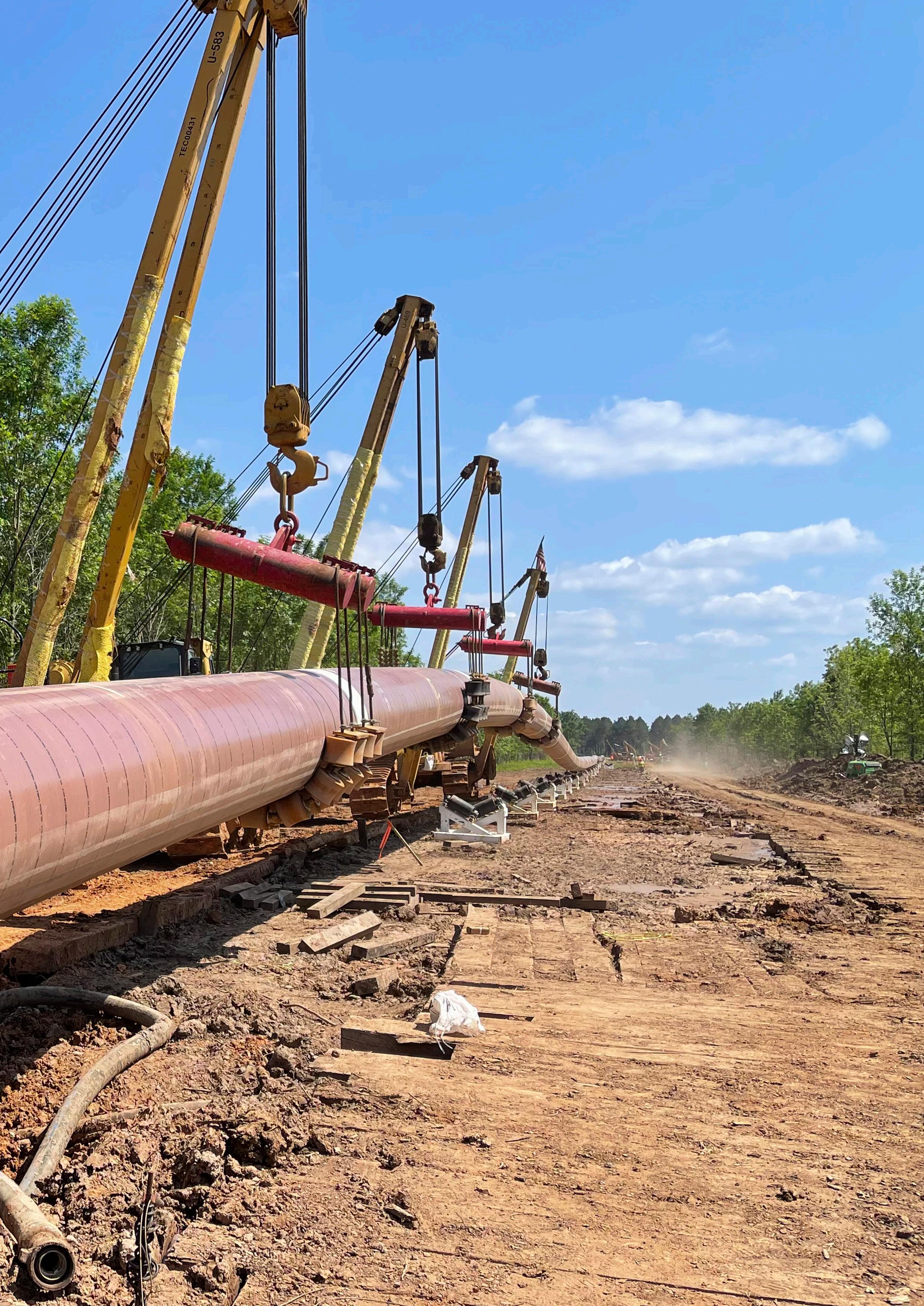
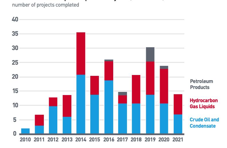 Figure 3. Side booms lowering pipe into a ditch.
Figure 2. US petroleum liquids pipeline projects (2010 - 2021). (Source: US Energy Information Administration Liquids Pipeline Projects Database)
12 World Pipelines / COATINGS & CORROSION 2022
Figure 4. A summary of the key deliverables enabled by a collaborative approach.
result, SPC had to balance all aspects of the business to provide products for various ongoing projects. The resulting balancing act and collaboration between the SPC team and Michels were ultimately essential to this project’s success. This kind of in-depth participation among all stakeholders will be essential to successful projects going forward.
Stakeholder coordination and optimisation
The success of all significant projects depends on an ever-growing and evolving alignment between invested parties throughout the project’s duration. Each stakeholder likely has the primary goal of a successful and profitable project, but that may look a little different along the way, and each party may have some distinct priorities. For example, when it comes to corrosion protection, the asset owner typically issues a suite of documents from their Engineering Standards (ES), which include the use of the most technically advanced, tested, and available coating products, which often come with the most significant price tags.
In some cases, the funding and estimate to complete the project may get trimmed down in size. Each general contractor, and their subsequent subcontractors, may need to ‘trim’ costs, collectively resulting in a lower installed cost. Often, the coating manufacturer is asked for the best coating system to meet the environmental conditions, but then asked to provide a solution
that reduces surface preparation, thus significantly reducing cost. Or, sometimes, a subcontractor may have a recommended solution that is not in the ES but one with which they have had immense success, productivity, and efficacy. This often requires a deviation request and accompanying documentation to justify the change. All these variables can result in a system where some or all parties have had to make concessions. The key throughout this process is to agree and align before starting the job to ensure the project’s exceptional success. In this process, project and material history and best in class activities should be considered.
Luckily, when the Gulf Run Pipeline project started, all the stakeholders set out with a similar goal; execute a safe, reliable, and industry-leading project. And that goal has helped keep them aligned. Price is what one pays for value. And in this case, the value came through the careful coordination, planning, and collaboration of all parties involved.

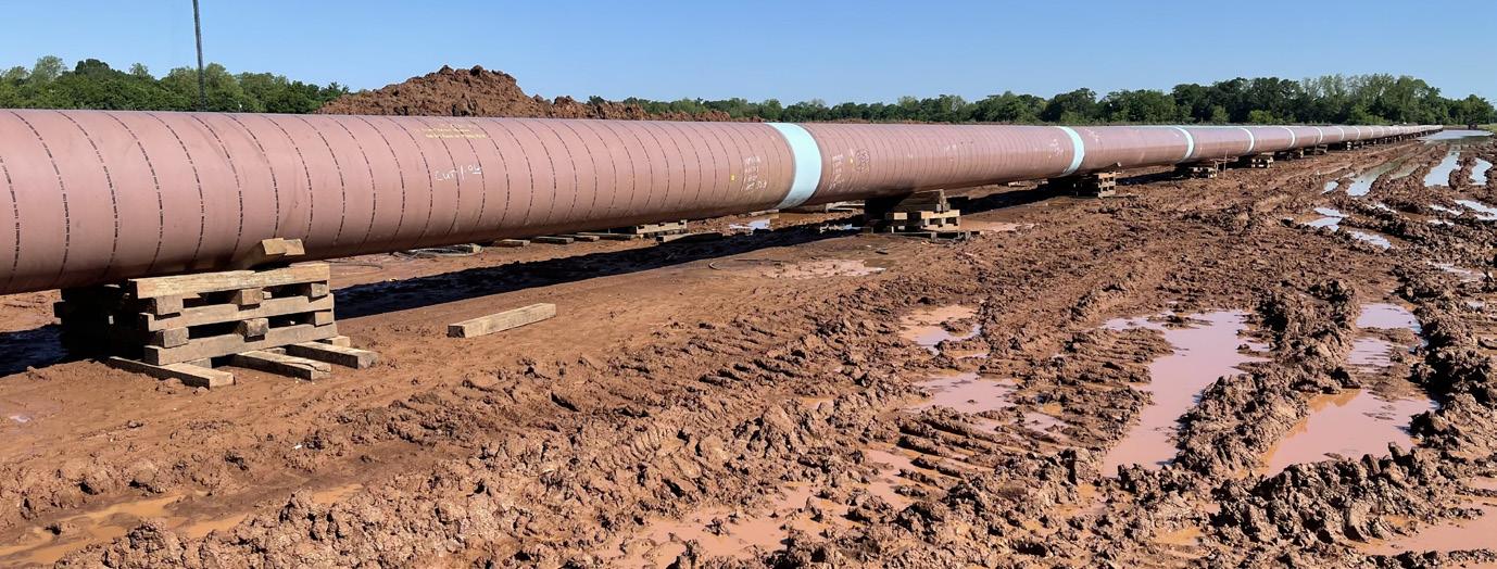 Figure 5. Epoxy/polyurethane girth weld coating, SP-2888 RG, on HDD pipe.
14
Natale Fabrizio Civardi, Owner, LK2 and Umberto Canali, HDD Project Manager, Impresa Trecolli S.p.A., Italy, talk about a challenging project in Italy involving the use of a new special abrasion resistant overcoat for HDD applications.
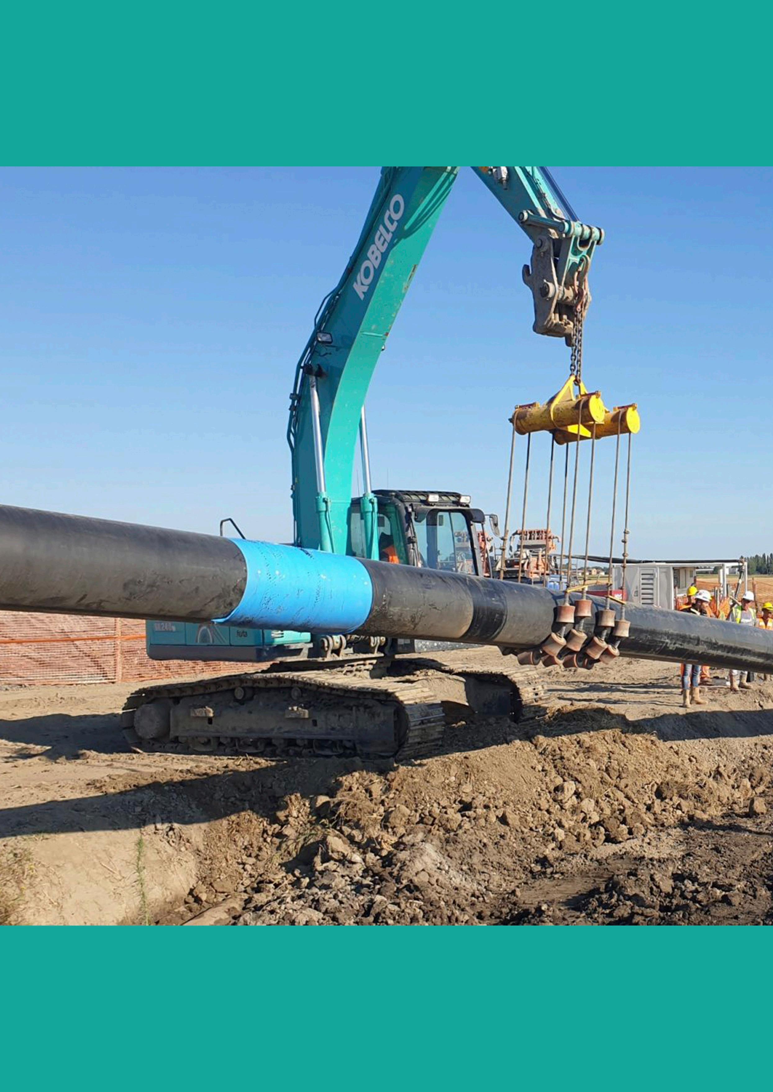
Horizontal directional drilling (HDD) is the most commonly used technique to install sections of pipelines across areas that must remain undisturbed, such as roads, lakes, buildings, railroads, or river. This method allows the passage of pipes in areas considered to be high risk with the least environmental impact and ease in releasing work. But what are the risks, and what is the most common damage caused to the pipe by pulling during drilling? Protecting the pipe’s main coating is the aim in these situations. Cathodic protection (CP) and casings may be insufficient to keep the properties of the anti-corrosive coating of the pipeline unchanged. In addition, it should be considered that HDDs commonly are made in areas where it is almost impossible to repair pipelines, so it is essential to find a solution that preserves the life of the pipeline without any necessary regular maintenance. For these reasons, it was necessary to find a high-strength mechanical solution that would ensure very high performance during pulling.
Achieving abrasion resistance
Resistant overcoat products (ARO) are specifically designed to protect the primary corrosion coating from damage during pipeline directional drilling applications, boring, river crossing, and installation in rough terrain.
Case study
At the beginning of 2022, LK2 was involved in the reconstruction of the San Salvo-Biccari DN 650 (26 in.), 75 bar natural gas pipeline and related works project. The entire project has been of central importance and crosses three regions (Abruzzo, Molise, and Puglia) and three provinces (Chieti, Campobasso, and Foggia) in Italy.

15
The new pipeline totally replaces the existing one for a total length of about 89 km and will substantially contribute to increasing flexibility in the operation of the natural gas transportation system between the South-North routes, as it will also affect works related to connections and branches linked to it.

Different HDDs were planned along the pipeline: one of them was carried out in May 2022; and a second one in August 2022. For those HDDs, LK2 was engaged in the project as a supplier of HDD external mechanical protection for the pipeline.
The collaboration with Impresa Trecolli S.p.A., the project contractor, and Festa S.p.A., the company contracted for the drilling, was very productive and made it possible to better recognise and study in advance the critical issues of the project. The LK2 team was able to successfully apply its knowledge to meet this important challenge.
The mechanical protection specification should be:
) Ensure the integrity of the anticorrosive coating: protection of pre-applied anticorrosion field joint coatings and mainline coatings.
) Protection against impact, abrasion, gouge, punctures, and tears that may result from directional drilling, or severe in-service conditions.
) Easy and fast application.
pp. 200 - 204
Date August 2022
End user SNAM Spa
Contractor IMPRESA TRECOLLI S.p.A. has been active mainly in the field of excavation and earthmoving work for the construction of industrial pipelines and oil, gas and water pipelines. Extending its activities over time to mechanical erection works for the complete realisation of oil and gas pipelines with related compression and pumping plants
Drilling contractor FESTA S.p.A. operates in the field of engineering and in the construction, repair, and maintenance of infrastructure underground through traditional and innovative technologies. The systems used belong to the large family of NO-DIG or TRENCHLESS TECHNOLOGY. Horizontal Directional Drilling is the strength of Festa S.p.A.
Rig HERRENKNECHT HK250T
Location Larino (Chieti) – Italy
Pipeline diameter DN650 (26 in.)
Pipeline thickness 11.1 mm
Crossing length 443 m
Crossing depth 30 m
Underground surface of the crossing 930 m2
Survey date 11 August 2022
Thanks to decades of experience in oil and gas, and corrosion prevention, LK2 had already developed a product that meets the demands of HDD projects.
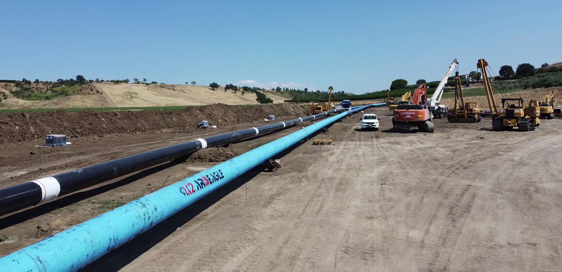
AroEagle, its own ARO, consists of a triaxial fibreglass fabric, supplied in different thicknesses/sizes, impregnated with methylene diphenyl diisocyanate (MDI)-based polyurethane resin which cures once activated by water (MCU).
The aim of the product is to grant quality and strengthen the integrity of the overall coating on the entire pipeline. This ARO covering both the pipes and the field joints provides homogeneity over the entire pipeline and thus reduces the number of potential weak spots.
AroEagle has already been used for 15 HDD projects and more than 12 km of covering, mainly in Italy. Thanks to the ease of application and an excellent balance between drying time and application time, this product is based on the real needs of the users.
Table 1. Project ‘HDD TERRE ARMATE’ report issued by contractor (Impresa Trecolli S.p.A.) Reconstruction of the San Salvo-Biccari DN 650 (26 in.), 75 bar natural gas pipeline and related works
Figure 1. Total pipeline coating with AroEagle.
16 World Pipelines / COATINGS & CORROSION 2022
Figure 2. HDD Terre Armate construction site – Larino (Chieti).


Read the issue here Subscribe for free: www.globalhydrogenreview.com
new magazine focused on the global hydrogen sector The Autumn issue of Global Hydrogen Review is out now
A
LK2’s ARO solution is suitable for several applications: ) HDD.
) Micro-tunnelling.
) Boring.
) Rock shield mechanical protection.
) Trenchless pipeline construction.
) Field joint coating (FJC).
) Factory direct application.
) District heating pipeline protection.
Following an intense and complex pulling phase that lasted about 20 hours, on the morning of 10 August, the execution of the HDD crossing ‘Terre Armate’ was finished.
It had been a real challenge with nature: especially for the initial, and final, parts of the drilling, that were characterised by a lithology not particularly favourable to the application of HDD technology.
The presence of moderately thickened gravels with clasts of polygenic nature and a maximum diameter of about 80 mm of sub-angular shape, were obstacles that tested AroEagle.
The project also involved overcoming a steep area with a 33% slope and a difference in elevation between upstream and downstream of about 45 m: some truly challenging conditions.
Thanks to the construction of the HDD variant, it was possible to avoid laying the pipeline along the entire slope with traditional open excavation techniques and the construction of reinforced soil, thereby minimising the environmental impact and improving the pipelaying cover.
After completing the drilling, data was collected and analysed, and it was found how crucial proper joint covering and efficient protection from adverse terrain are.
Project data report
The ‘Project Data Report’ (Table 1) was prepared to verify the pipeline draft processes, and obtain data regarding the effectiveness of external mechanical protection for the pipeline.

Average value of insulation resistance calculation
The insulation resistance value is expressed in 'Ω*m2’ and was obtained by applying the formula:
resistance must be calculated at the conventional value of soil resistivity of 50 Ω*m.
UNI 11094 specifies that insulation resistance values are affected by the resistivity of the environment. If the average measured soil resistivity is greater than 80 Ω*m, the insulation

The insulation resistance value obtained is evaluated about the following parameters of reference:
The test involved the performance of measurement techniques for CP referred to in standard UNI EN 13509 in addition to the following other normative references:
) UNI EN 12954 Cathodic protection of buried or immersed metallic structures – General principles and application for pipelines.

) UNI 11094 General criteria for implementation, check and control as integration of UNI standard EN 12954 also in the presence of leakage currents.
) UNI EN 15257 Cathodic protection – Certification of personnel.
To assess the level of damage to the coating of the pipeline section installed with trenchless technology, the following activities were carried out:
) Ground resistivity measurement.
) Putting the pipeline into protection.
) CP potential measurement.
) Average value of insulation resistance calculation.
All the tests activities were performed in compliance with the procedure: GASD R.04.20.53 dated 23/12/2015.
Conclusion
According to the report – which evaluated the level of damage suffered by the main coating of the pipeline section laid with trenchless technology under high mechanical stress – a very high level of performance was achieved. Calculations made after the surveys reported the condition of the coating to be more than excellent.
18 World Pipelines / COATINGS & CORROSION 2022
For decades crack inline inspection (ILI) tools have been helping operators address most of the features in the pipelines. However, ILI technology has now reached a point where the conventional shear wave technique is no longer good enough to identify remaining features or because of the crack surroundings (i.e. weld geometry). Pushing the industry to evolve, NDT Global developed an innovative technology, PROTON TM , a versatile phased
 Rogelio Guajardo, Head of Analysis UC, NDT Global, Germany, talks about detecting, sizing, and characterising challenging crack features.
19
array platform providing operators complementary information to efficiently address and manage their crack programme. When evaluating a crack feature, it is important to look beyond the feature length and depth, and pay attention to the crack location and any other variables. This provides a unique perspective to the assessment. To better understand the context, the analyst must increase the assessment accuracy.
Should we assess a crack with the same dimensions that is in a perfectly smooth trimmed ERW, compared to a DSAW where the wall thickness (WT) in the weld is 150% of the nominal WT? Probably not! Would we treat the crack in the same way if it were in a misaligned long seam or one with a peaking?


By putting features in context to the surroundings at the time of the assessment, we can run an efficient integrity management programme (IMP) where we can intelligently allocate our resources (i.e. economical and personnel) addressing the features based on need.
Current ILI crack tools report feature length and depth, referencing a WT measured across the entire pipe joint –so how can we obtain a holistic view? This is where PROTON comes into play.
Detecting, sizing, and characterising challenging crack features
PROTON is an ultrasonic inspection platform that uses phased array sensors. These are the same type of phased array sensors used by NDE technicians in the field, but in an ILI tool recording 360° and travelling at 1.4 m/sec. Phased array makes the inspection platform versatile, as it can have the same mechanical design, multiple refracting angles or samples, allowing it to be configured for specific applications by just updating the firmware.
This platform combines all the knowledge and technological advancements that NDT Global has made in the field of crack detection over the past 20 years and more. Pulse echo (PE) is still the ‘battle horse’ used for detection, the difference is that now there might be multiple refracting PE angles and not only one, the conventional 45° shear wave. PROTON also includes one or more pitch and catch (P&C)
Figure 1. Weld characteristics obtained from the contour sampling. Figure 2. Weld type geometries obtained from the contour sampling. 20 World Pipelines / COATINGS & CORROSION 2022 Table 1. Crack technology comparison based on key attributes Attribute Standard crack (UC) Highresolution crack (UCx) Pitch and catch crack (EVO Eclipse UCx) Phased array crack (PROTON TM) Highresolution No Yes Yes Yes Sampling scenario 1 PE angle 1 PE angle 1PE angle 1 P&C angle 2+ PE angle 2+ P&C angles 1 contour sample Crack tip measurement No No No Yes Tilted and skewed features depth sizing limits 10° & 5° 10° & 5° 45° & 10° 45° & 10° Depth tool tolerance 1…<4 mm ≥ 4 mm ±1.0 mm N/A ±0.8 mm ±1.2 mm ±0.8 mm ±1.0 mm ±0.7 mm ±0.7 mm
Input
52
Flaw
angles
Table 2.
parameters for the assessment Yield strength (psi)
000 CVN (ft-lb) 5 Ultimate strength (psi) 66 000 Diameter (in.) 24 Elastic modulus (ksi) 29 500 Wall thickness (in.) 0.281 MOP (psi) 1011
shape Elliptical
overcoming the tilted and skewed limitations from PE, like NDT Global’s EVO Eclipse UCx. The selection of the angle and techniques used (PE and P&C) is based on the application and the type of features that need to be addressed.
As standard, PROTON will record at least four data sets (2 PE and 2 P&C) for crack detection, identification, and sizing. The technology has conventional indirect measurement capabilities (PE and P&C) for multiple angles for every crack feature, but also has the possibility to provide the direct crack depth based on the tip. This technology has previously been seen in field verifications, but PROTON is enabling this capability for an ILI tool. Table 1 provides a simple comparison between available crack tools.
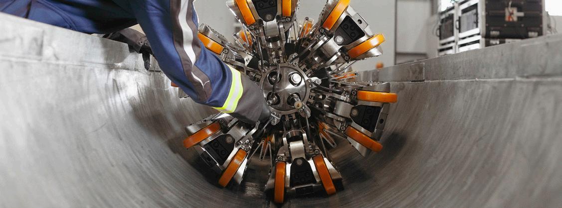
When we look at Table 1, it appears that there are not too many differences between EVO Eclipse UCx and PROTON. There is, however, one key element in the sampling scenario that makes all the difference and provides the context we started talking about –the ‘contour sample’.
What is this ‘contour sampling’? This is a highresolution 0° measurement – a high circumferentially speaking redundant WT measurement sampling. Because of its characteristics, it is possible to extract additional data points that surround the crack and provide a unique perspective on how to address it.
Some key data points that can be extracted from this sample are related to the weld characteristics such as the weld height (local WT), weld width, weld misalignment, and/or weld peaking (Figure 1). This information not only identifies the presence of a weld misalignment, for example, but the actual measurement of it. However, that is not all; the sample allows analysts to confirm the weld type based on its geometry (i.e. rounded = DSAW) using artificial intelligence algorithms (Figure 2). This information is invaluable during analysis as it will improve feature identification and discrimination between weld ‘hi-low’ and true features, and while performing the assessment of the feature (as the toughness levels for the DSAW may not be the same as in an ERW). With this contour sampling, PROTON can provide at least five additional data points associated to the crack that provide context.

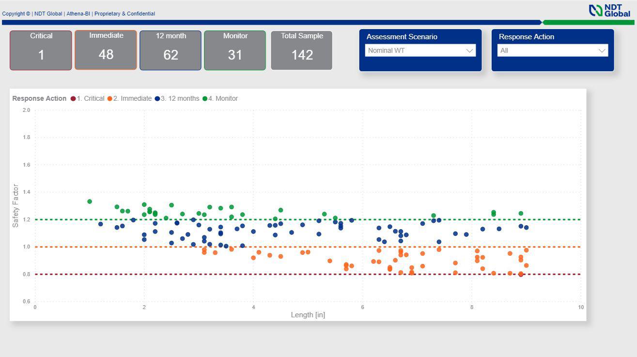
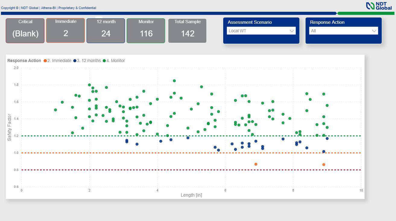
The input data for the assessment in Table 2 depicts the advantages of contour sampling.
Scenario 1
Safety Factor (SF) is calculated using the nominal WT, referencing the information in Table 2 for a sample of 142 crack-like features with depths and lengths oscillating between 0.040 - 0.160 in. and 1.0 - 9.0 in. respectively, there will be a total of 111 features (78%) that need to be verified within a year. From the 111 features, 49 (1 critical and 48 immediate) require prompt attention. Figure 3 summarises the results.
Figure 5. SF calculation using local WT and peaking tool tolerances.
Figure 4. SF calculation based on the local WT.
Figure 3. SF calculation based on nominal wall thickness (WT).
COATINGS & CORROSION 2022 / World Pipelines 21
Figure 6. PROTON Phased Array inline inspection service allows wide adjustments to achieve optimal performance in pipeline operators’ assets.
Scenario 2
PROTON provides the local WT (Figure 1) for each crack.
This information is used to calculate the SF. Because of the ID and OD weld caps, the local WT is higher than the nominal WT reducing conservatism from the calculation.
In this scenario (Figure 4), the number of required verifications within 12 months has reduced from 111 to 26, two of which are the most critical. This reduction of over 70% brings efficiencies to the IMP.
Scenario 2.1 Peaking
PosiTector ® Inspection


n N E W L a r g e r 2 8 ” i m p a c t r e s i s t a n t c o l o r t o u c h s w i t h r e d e s i g n e d k e y p a d f o r q u i c k m e n u n a v i g a n N E W O n g a u g e h e l p e x p l a i n s m e n u i t e m s a t t h o f a b u t t o n n N E W We a t h e r p r o o f , d u s t p r o o f , a n d w a t e r r e s i s
I P 6 5 r a t e d e n cl o s u r e n N E W E r g o n o m i c d e s i g n w i t h d u r a b l e r u b b e r i z e n S h o c k a b s o r b i n g p r o t e c t i v e r u b b e r h o l s t e r f o r i m p a c t r e s i s t a n c e n Tw o y e a r w a r r a n t y o n g a u g e b o d y A N D p r o b e n C o n f o r m s t o n a t i o n a l a n d i n t e r n a t i o n a l s t a n d a r i n cl u d i n g I S O a n d A S T M n N E W A u t o r o t a t i n g d i s p l a y w i t h F l i p L o c k n N E W S c r e e n C a p t u r e s a v e 1 0 0 s c r e e n i m a g e r e c o r d k e e p i n g a n d r e v i e w
For certain features, PROTON flagged features in areas where peaking is present. For those features, the tool tolerance is different, knowing this, the features can be re-evaluated, and the SF updated. After the evaluation (Figure 5), one additional feature was added to the immediate category and two were identified as requiring verification within 12 months. Still this represents 82 digs less in one year compared to Scenario 1. This additional peaking information provided context to the features and changed the way we assess them.
PROTON provides a holistic view of the crack features and its surroundings, allowing pipeline engineers to manage their assets efficiently. Who doesn’t want to reduce 82 digs, as in our example? We’ll let you to do the math on the savings. PROTON is one of a kind; there is no other tool in the market that can acquire that level of detail from its data that results in high accuracy of the delivered results. This platform is pushing boundaries and challenging the industry to move forward, changing the way crack programmes are managed.
References
1. GUAJARDO, R.(2019), ‘High-Resolution Inspections for Crack Detection: The Next Level of Accuracy’, Pipeline Pigging and Integrity Management Conference.
Houston: Clarion Technical Conferences & Great Southern Press.
I n t r o d u c i n g t h e n e x t g g a u g e b o d y f o r a l l y o u
DeFelsko Corporation l Ogdensburg, New York USA Tel: +1 315 393 4450 l Email: techsale@defelsko com Backwards Compatibility! The PosiTector gauge accepts ALL coating thickness (6000/200), environmental (DPM), surface profile (SPG/RTR), salt contamination (SST), hardness (SHD/BHI), gloss (GLS), and ultrasonic wall thickness (UTG) probes manufactured since 2012 Customized Inspect Kits... Build your own kit a selection of gauge bodies probes to suit your needs Table
of IMP response
Safety
SF ≤ 0.8
shut down the line 0.8 < SF ≤ 1.0
reduce pressure and verify
15 days 1.0 < SF ≤ 1.2
verify
12 months. No
on pressure SF
1.2
action
only feature monitoring
A l l G a u g e s F e a t u r e . . .
3. Example
action
factor Response action
Critical =
Immediate,
within
12 months,
within
action
>
Monitor, no
planned
Portable PIP testing possesses all of the attributes needed for scalable, next generation non-destructive pipeline PMI, says James Dean, CEO, Plastometrex, UK.
onformance with PHMSA’s ‘Mega Rule’ centres on thorough application of risk-based integrity assessments. Recent publication of the final ‘Mega Rule’ set further into motion a series of regulatory expectations which increase the scope and scale of the requirement to accurately measure and record the material properties of applicable oil and gas transmission pipelines.
While the legislation would see project owners and asset managers benefiting from a clearer, more-informed view of the status of their assets, the availability of technology and processes that satisfy Mega Rule requirements has faced some challenges. Bottlenecks, regulatory hurdles, and a struggle to deploy commercially viable and scalable technologies have been a cause for concern. The concern is valid. With a requirement of 50% of MAOP verification to be completed by mid-2028, the race is on!
This leads us to PIP testing. Already heavily validated, PIP testing is designed to extract accurate stress-strain curves from indentation test data. Based on a scientific methodology referred to as indentation plastometry, the evolution of PIP testing from academia to industry can be tracked through dozens of case studies and scientific publications, including those covering the testing of case-hardened layers and large, inhomogeneous aluminium forgings. Accuracy and insightful

23
data are two key aspects of PIP testing, but that’s not all – PIP testing is also very, very quick!
Change, however, can be difficult. New innovations, justifiably, should be studied carefully and validated thoroughly, ensuring their ability to stand up under rigorous use in material property testing environments. In this case, however, it may be worth the effort, as pipeline operators (and those with past PMI and non-destructive testing experience) will relate to the need to employ novel technologies that are accurate, reliable, and suitable for meeting the scale of the challenge – a need that many have so far found difficult to satisfy.
With a benchtop PIP testing device commercially available and already in use providing faster, more costeffective, and more insightful lab-based materials properties testing worldwide, we have now turned our focus to a new, portable version of the technology which is being developed specifically to address the Mega Rule challenges. The focus is on developing a system that is accurate, quick, and easy to deploy (single-person use), requires minimal training, and is scalable commercially. The system will also link to a cloudbased digital platform for TVC-compliant record keeping.
PIP testing
Uniaxial tensile testing has not changed much in over 100 years, despite some major limitations. In fact, in a survey of more than 450 manufacturing companies conducted by Plastometrex, 45% of the respondents selected tensile testing turnaround times as being the biggest bottleneck in the smooth running of their businesses. That is mainly because tensile testing can be cumbersome and time-consuming, and usually requires access to large volumes of material.
Enter PIP testing – a technology developed and validated primarily through lab-based tests comparing PIP outcomes
with results from conventional tensile tests by Plastometrex – but, and perhaps more convincingly, in collaboration with some of the world’s largest technology companies and most prestigious academic institutions.
In its simplest form, PIP testing involves the following sequence: creation of an indent by applying a load to an indenter head, measurement of the indent shape using an integrated stylus profilometer, finite element modelling of the indent procedure and iterative modification of the parameters in a constitutive plasticity equation, optimisation towards convergence of modelled and experimental profile shapes, and determination of the underlying stress-strain behaviour.
As for its history, Professor Bill Clyne, Chief Scientific Officer, Plastometrex, had initially stepped up to meet the challenge of reliable conversion of indentation test data, in the form of load-displacement curves or residual indent profiles, into full stress-strain curves, almost 20 years ago. Since then, Plastometrex has raised over £6 million in venture capital and UK government funding to commercialise the PIP testing technology with a mission of making mechanical testing simpler, faster, more versatile, and more insightful.
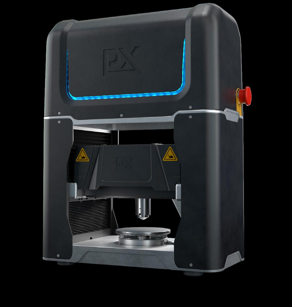
The Indentation Plastometer (Figure 1) emerged in late 2020. It is a benchtop macro-mechanical testing device that measures metal strength parameters (stress-strain curves) from a quick and simple indentation test. Its development and validation have been supported through collaborations with organisations including Ovako, The Welding Institute (TWI), the National Physical Laboratory (NPL), Oxford University, and Desktop Metal.
In addition, and following its own technical due diligence, the testing, inspection, and certification giant – Element Materials Technology – took its own stake in the business. Machines are now in use at sites all over the world, including MIT, FIU, the Worcester Polytechnic Institute, and Oxford University.
PIP testing in action
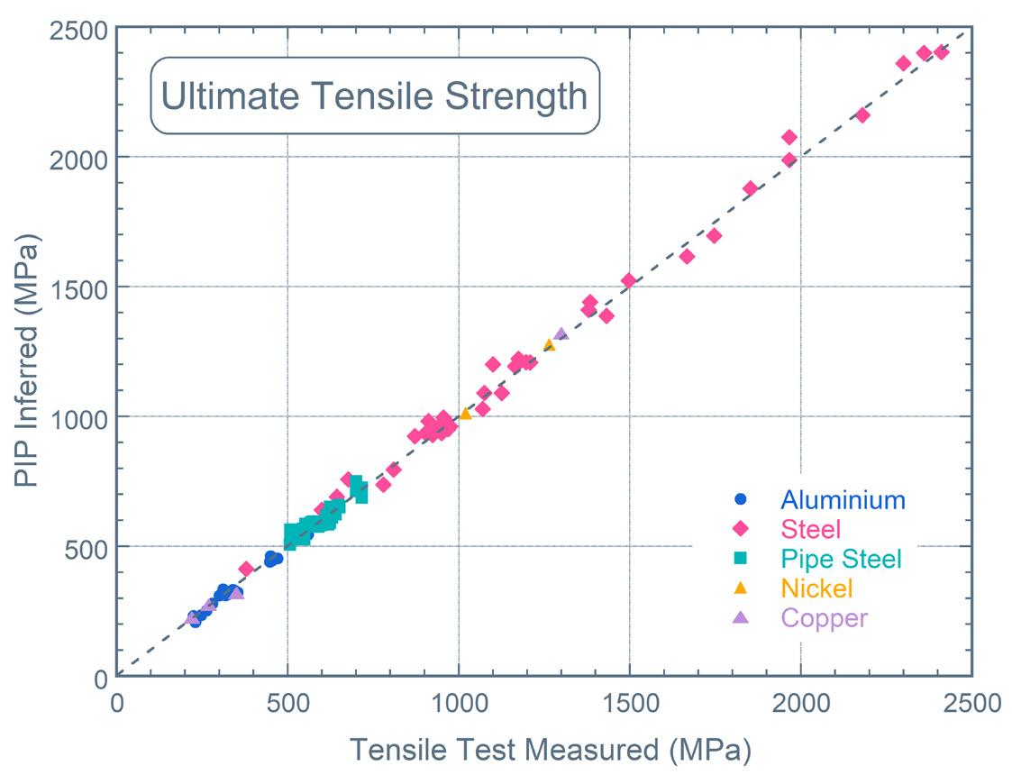
PIP testing enables the testing of real components with minimal sample preparation required. It is used for a diverse range of applications, such as small-scale testing of novel aerospace alloys, high throughput testing in combinatorial alloy design, forensic failure analyses, the structural characterisation of additively manufactured metals, and spatial mapping of property changes across welds, among others. Examples of validation data (Figure 2) are available for the yield stress and ultimate tensile strength of a range of common engineering metals.
Fully integrated and fully automated, the technology allows users to switch from conventional mechanical testing to a process that can measure full tensile stress-strain curves and metal strength parameters in just a few minutes. The technology has been developed to reduce testing costs and testing turnaround times, and to help eliminate the lack of versatility that is the hallmark of conventional tensile testing.
In-ditch launch
Building on the success of the benchtop device, the Portable Indentation Plastometer, arriving summer 2023, is being
24 World Pipelines / COATINGS & CORROSION 2022
Figure 1. The Benchtop Indentation Plastometer from Plastometrex.
designed and constructed for in-field testing of high-value metal assets in support of positive material identification, in-situ monitoring of material degradation over time, and asset and component life extension calculations.

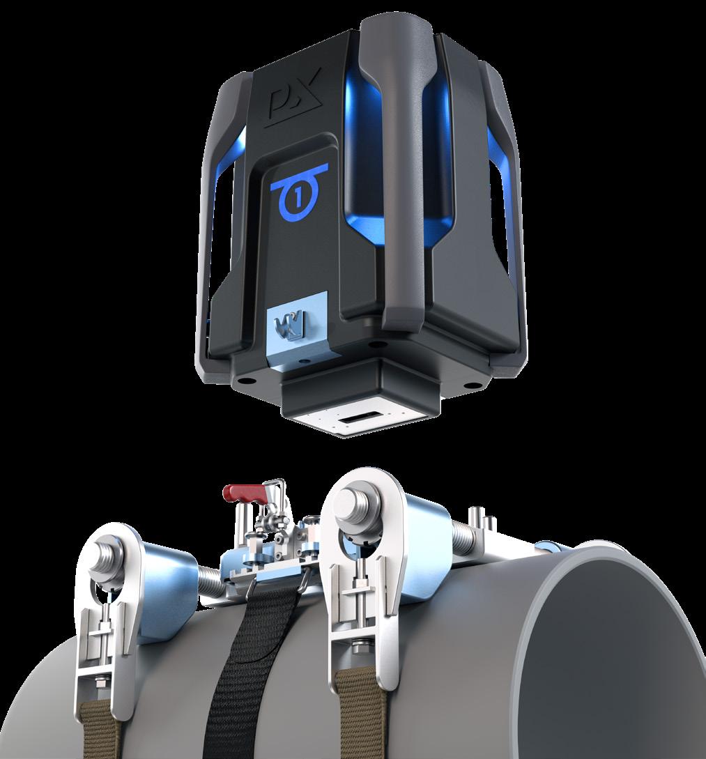
The full technical specification for the portable equipment (Figure 3) has been developed in consultation with asset integrity service providers including ROSEN, Mistras, Acuren, DNV, RSI pipelines, and Element Materials Technology. What emerged from those discussions was, quite naturally, a requirement for the system to be accurate, but also a requirement for the system to be easier and faster to use than any of the current in-ditch testing technologies.
The new Plastometrex system is single-person use, with user-guided workflows designed to make the operating steps involved with testing metal pipes as simple as possible. These steps include preparation of the pipe surface – typically involving a surface grinding operation using hand-held, off-the-shelf tools. Once the surface has been adequately prepared, a cradle is attached to the pipe using a bespoke strap-tightening system. The handheld indenter module is then attached to the cradle which houses power and electrical connections. Once the indent has been created, the indenter module is detached and the profilometer module is attached.
Unlike the benchtop system, which uses a mechanical stylus profilometer, the portable system uses an optical profilometer that is based on white light interferometry, providing almost instantaneous access to the full 3D profile. After making software-driven corrections to account for pipe curvature and far-field tilt, the profile shape is analysed in the exact same way that it is with the benchtop system (through an accelerated inverse finite element analysis). The portable PIP testing system is, therefore, a direct derivative of the benchtop system, deployed in a different testing configuration, but employing the same proven scientific methodology.
Minimal training requirements ensure large numbers of personnel can be trained quickly to use the equipment. Test results should be available for inspection immediately, with no finessing of the data needed following further, offsite analyses. The equipment is compact, robust, and easy to handle. It is also durable and can be carried in a technician’s truck as part of their standard equipment.
Mega Ruling
The Mega Rule presents a challenge to asset owners, asset operators and asset service providers that are involved with onshore steel transmission pipelines in terms of collecting or retaining traceable, verifiable, and complete (TVC) records that document material properties.
The Mega Rule was divided into three separate final rule actions, the first of which was published in October 2019. Part one of the rule requires operators of certain onshore steel gas transmission pipelines to reconfirm the MAOP of applicable segments – a perfect application for the Plastometrex portable system.
The Mega Rule further addresses material properties verification, the expansion of integrity assessments beyond high-consequence areas (HCAs), strengthened requirements for assessment methods, and other topics related primarily to threat evaluation and the assessment of risks.
Clock’s ticking
The clock is ticking as PHMSA, citing existing requirements for collecting and using the data elements from ASME/ANSI B31.8S, has revised its final Mega Rule, appearing 24 August 2022, on the Federal Register. It states that operators must begin applicable data integration on the effective date of the rule – noted as 24 May 2023 – and integrate all attributes within 18 months of this rule’s publication date. And herein lies the major challenge – time!
Part one went into effect 1 July 2021, setting expectations for pipeline operators to have a plan in place to verify MAOP, and requiring that 50% of that verification be completed within the first seven years – by 3 July 2028. The final Mega Rule affirms that applicable documentation must be maintained for the life of the pipeline, and with the
COATINGS & CORROSION 2022 / World Pipelines 25
Figure 2. PIP testing validation data for yield strength and UTS.
appropriate TVC records. If the relevant records necessary to substantiate MAOP are not TVC, the burden of testing and inspecting is shifted as operators must present their findings to PHMSA.
The final rule additionally stipulates that pipelines must be inspected within 72 hours following the cessation of extreme weather events, after the operator reasonably determines that the affected area can be safely accessed by available personnel and equipment. The urgency is real. Integrity assessments of pipelines will be required at least once every 10 years.
Beating the clock
Quicker tests, using equipment that requires only one minimally trained operator can help support pipeline operators struggling with significant time constraints associated with the Mega Rule. From a testing perspective, the ability to scale up the appropriate technology quickly, and perform faster and more effective testing, aligns with what industry representatives are
asking for. In fact, scaling up will be imperative to meet the testing needs across (potentially) a large number of digs in a brief period of time.
What we are hearing at Plastometrex is that industry stakeholders do not want equipment that is too fragile, too expensive, or too hard to handle. In our view, the solution should be portable enough to carry in the rear of a utility vehicle, robust enough to withstand potentially harsh weather conditions, and practical enough to comply with the legislation. The business need revolves around safety, compliance, and efficiency. The faster the testing process (and the quicker the scale up), the less time there will be wasted waiting for data to be compiled, uploaded, analysed, documented, or acted upon.
The portable Indentation Plastometer meets all such requirements, equating to less time in the ditch.
PLXUS – TVC records solved
PHMSA noted that, at a minimum, an operator should consider the same set of data on a periodic basis and analyse changes and trends that would indicate the need for additional integrity evaluations. For this to be feasible, results data should be stored in a centralised and easily accessible database that is compliant with the relevant regulations in the relevant jurisdictions. The over-application of assumptions in the absence of real data, PHMSA asserts, even if those assumptions are conservative, can lead to skewed or otherwise inaccurate risk analysis results.
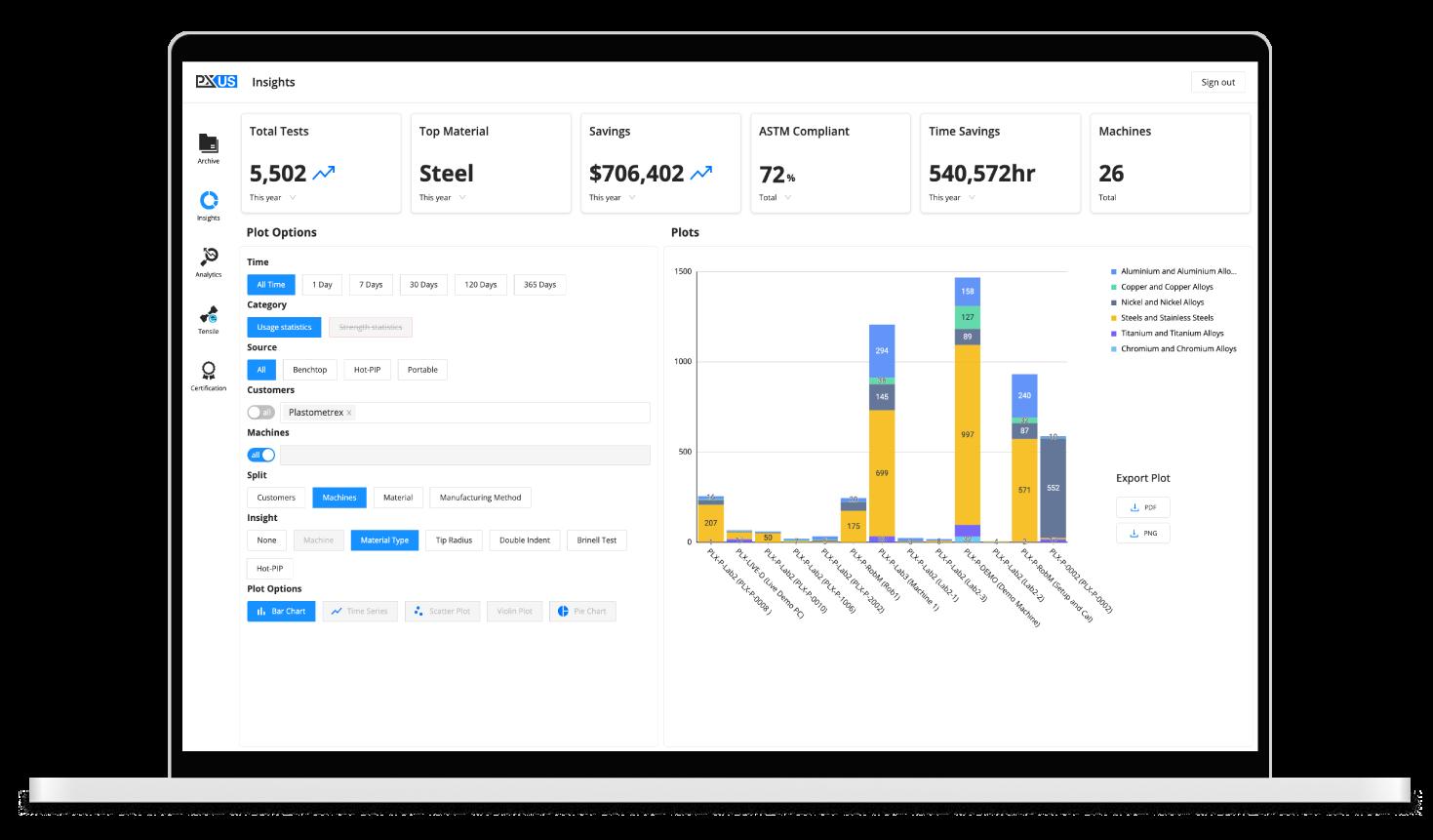
On this basis, Plastometrex is developing its own digital platform (called PLXUS) for the automated collection, storage, and analysis of pipe testing data. This platform already exists for the benchtop device (Figure 4), and is currently being extended to support PHMSA’s TVC record-keeping requirements. Like the benchtop device, results will be stored immediately in the PLXUS digital platform if a Wi-Fi signal is available, or stored locally until a Wi-Fi signal does become available. These datasets should therefore be available to colleagues that are offsite and/ or in different locations, allowing real-time and in-ditch decisionmaking. Over time, and with sufficient data, the PLXUS digital platform could be used to provide an overview of the health of the pipe network, to support reductions in overly conservative safety margins, and to support predictive maintenance scheduling.
Beyond the Mega Rule
Prolonging the life of the US gas pipeline infrastructure is critical from an energy security point of view, as is the ability of energy companies to meet growing sets of diverse energy demands. It’s perhaps even more important in this age of decarbonisation and growing infrastructure demands, including those associated with the capture, storage, and transportation of hydrogen which will also require measurement and/or reconfirmation of material properties.
Collecting this data requires accurate and commercially viable testing processes and technologies that can be scaled at pace. Alternative technologies have already proven too difficult, too slow, too expensive, and too inflexible to reach the scale required. However, portable PIP testing possesses all of the attributes that are needed for scalable, next generation nondestructive pipeline PMI.
Figure 3. The Portable Plastometer from Plastometrex.
26 World Pipelines / COATINGS & CORROSION 2022
Figure 4. PLXUS, the digital platform from Plastometrex.
olyethylene (PE) has revolutionised low pressure ( < 10 bar) gas pipeline design and has been used for the last 60 years. There are 100 000 km of PE gas infrastructure networks in the world.
The success of PE pipelines has been achieved through a legacy of historical development and exacting gas industry requirements (product qualification, installation codes of practice, and gas engineering operational procedure). This has assured an exemplary reputation for safety and reliability,
whilst offering economic benefits and maintenance free asset life.
Based on its track record, PE gas infrastructure has been considered a potential candidate for hydrogen gas distribution, offering a potential low carbon solution for the decarbonisation of heat at the lowest cost and minimal disruption to customers.
Demonstrating the ability to use and repurpose PE gas network infrastructure for hydrogen is now the subject
 Dr. Christopher O’Connor, Principal Consultant of Energy Systems, DNV, UK, talks assuring the integrity and efficient maintenance of 21st Century PE100 hydrogen and methane gas pipelines.
27
of intense research. Whilst research is necessary to underpin the safety case for PE hydrogen pipelines, it also important to reflect on lessons that can be learnt from its historical use.
Human factors warning
PE pipeline infrastructure is only as good as the codes of practice used for installation, and the impact that human factors can place on risk to gas pipeline infrastructure.
Global operators of PE100 pipeline assets report that the major threat to PE100 pipeline integrity other than third party damage is poor fusion jointing. Joints are obviously a weak point in any engineering system. Axial or bending stresses caused by thermal expansion or contraction, or ground movement will increase the risk of failure of substandard fusion joints.
For hydrogen use it is critical that stronger quality barriers are developed to mitigate jointing issues. To reduce this risk, it will be necessary for asset owners to have a top-down vision and strategy, supporting governance throughout the pipeline lifecycle and ensuring adequate levels of monitoring, audit and inspection are in place to assure quality of pipeline build.
Understanding the PE fusion process
There are 3 main types of fusion joint geometry – butt weld, socket joint (electrofusion), and saddle joint (electrofusion). For each type, the fusion process involves heating PE, until the material reaches its crystalline melt-point at which it becomes a visco-elastic melt. In this melt state, under the action of pressure, the long chain-like molecules of PE can uncoil, disentangle and slide over each other (shear flow) as shown in Figure 1. It is in this state that the melt phases i.e. pipe to pipe end or pipe and electrofusion fitting interface, can be brought together allowing molecules to molecular mix. On cooling, chain mobility reduces, the chains re-coil, re-entangle and the crystalline zones are re-instated, resulting in re-solidification. The resultant fusion weld can be as strong as original parent material.

Successful fusion jointing of PE pressure pipes requires strict control of the prescribed welding parameters, which presents difficulties when working in environments such as wet, muddy, or dry and dusty excavations. However, stringent codes of installation practice and a high level of operator competence have demonstrated that fusion joints can be made successfully in such demanding conditions.
Another difficulty is reliable inspection of PE pipe joints using NDT, since radiography and ultrasonic cannot
 Figure 1. Molecular mixing of molecules during fusion.
Figure 2. Failure modes of PE100 pipe – internal hydrostatic pressure testing.
Figure 3. Ductile failure of PE100 pipe.
28 World Pipelines / COATINGS & CORROSION 2022
Figure 4. Bead quality control (bend back test).
reliably detect all key issues that are known to affect joint quality. Furthermore, techniques have not yet proved sufficiently reliable or cost-effective for field implementation. Consequently, to negate joint failure, it is considered a fundamental requirement that a robust quality assurance system is employed using established infield joint quality integrity assessments and selective destructive testing. Underpinning this approach must be a commitment to training and continuous assessment of workmanship competence.
Furthermore, there must be continual investment in equipment to ensure fitness for purpose.
Finally, the culture adopted by organisations must drive behavioural change such that operatives are self-regulating and take ownership for the quality of gas critical work.
Understanding PE pipeline failure modes

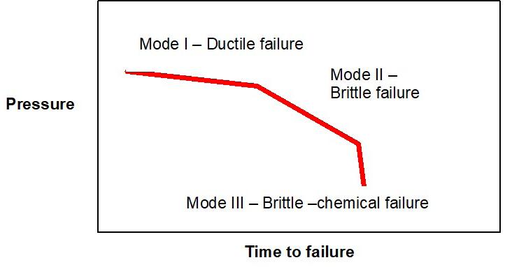
The established major failure modes for PE pipe are shown in Figure 2.
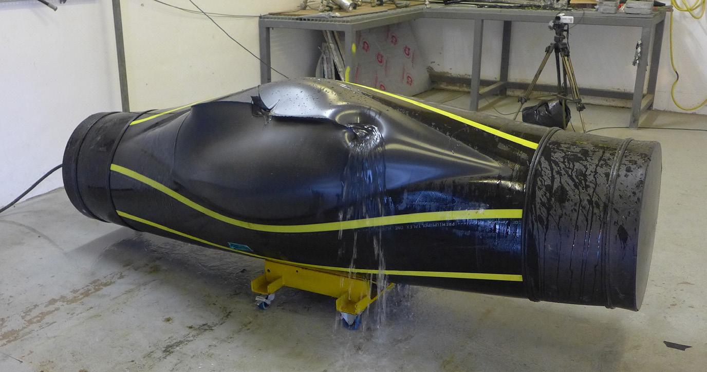
Ductile failure mode I, results in yielding and reflects a material’s propensity to undergo large-scale, irreversible ‘plastic’ deformation when under stress. The mechanism results in localised expansion of the wall section and final rupture of the deformed zone, as shown in Figure 3.
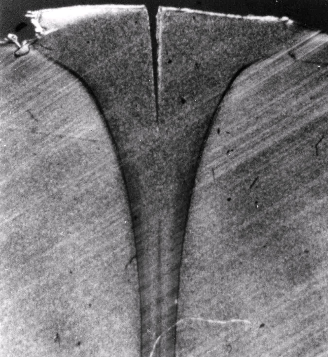
Failure Mode II is due to long-term sustained static loading at low stress which can result in the accumulation of creep deformation at stress concentrations resulting in slow crack growth (SGC) and stress cracking.
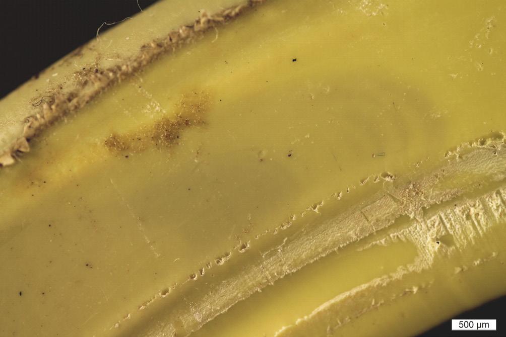
Stress cracks are brittle in nature and are characteristically smooth, featureless, and devoid of any yielding and deformation process, as shown in Figure 5.
Stress cracking can occur in butt fusion and electrofusion joints due to an array of potential installation defects, which introduce stress concentrations and weak points in the fused material structure. The applied stress may be static or dynamic (fatigue) in nature.
Butt fusion SCG failure modes
A threat to butt fusion joint integrity is the initiation of SCG at geometric defects (Figure 6) or contaminant inclusions (Figure 8), which act as stress concentrations. Secondary bending stresses, typically misalignment, uneven support or pivot points drive circumferentially cracking at these defects until the remaining ligament of
the weld becomes unstable, resulting in a transition to fast crack growth and catastrophic failure, as shown in Figure 7. The amount of gas released is dependent on the internal pressure and diameter of the pipe in question, and can be significant.
The following procedural factors can compromise butt weld quality:

Fusion pressure
Too high a pressure and all the molten material will be pushed into the weld bead, leaving ‘cooler’ material at the joint interface. Too low a pressure can lead to insufficient mixing of the molten material at the pipe surfaces.
WE MAKE THEM SO YOU CAN TRUST THEM TO PERFORM
Dairyland Electrical Industries is the world’s leading manufacturer of solid-state decoupling products for the corrosion protection industry. We’ve been making rugged and reliable products since 1983. After nearly 40 years, 99.99% of them still work. Learn more about our Always Rugged Promise: Dairyland.com /AlwaysRugged
WORLD LEADERS IN SOLID-STATE DECOUPLING
1. Drag pressure
Incorrect measurement of drag pressure to overcome pipe weight and the friction within the butt fusion machine. This threat can be mitigated by the automatic butt fusion machines, which calculate these parameters.
2. Melt temperature
Insufficient melt temperature will be result in higher viscosity melt, resistance to melt and molecular mixing, and ultimately poor fusion. Excessive temp (below thermal degradation)
could result in flow of material from the weld zone when fusion pressure is applied.
3. Pipe ovality
The fusion weld within a butt fusion joint is restricted to the pipe end area, consequently it is important that full use is made of the maximum available area.
4. Pipe end preparation (trimming) and contamination
If trimming is incomplete, the pipe ends will be uneven, some areas will still be oxidised or contaminated with dirt and dust, and when placed in contact with the heater plate, there will be gaps resulting in an uneven heat transfer across the pipe ends.
5. Pipe alignment
A certain amount of misalignment is inevitable (maximum 1 mm <180 mm diameter, 10% wall thickness >180 mm) assuming beads widths are within acceptable limits.
6. Heat soak time
If the heat soak time is too short, the pipe molten surfaces will not reach the required temperature and will cool quickly. This results in an increase in melt viscosity, crystallisation prior to fusion, and ultimately a ‘cold’ lap joint. A ‘cold’ lap joint may not exhibit any contamination, may be well aligned and perfectly trimmed. However, there will be no strength in the joint if subjected to bending and it will separate completely.
7. Dwell time
This is the time taken to remove the heater plate and bring the pipe ends together in a controlled manner to complete the joint. The faster they can be brought together, the less likelihood that the molten surfaces will have time to cool down. The effect of a long dwell time in a butt fusion joint will be the same as a short heat soak time and the joint will be ‘cold’ lap.
8. Gross and fine particulate dust contamination

Gross contamination such as dirt, hand cream, sweat etc will disrupt molecular fusion and compromise weld quality.
Fine dust particles can also be major threat. Whilst the butt fusion process experiences little melt movement during the making of the joint, it does push any finer dust particles towards the external and internal beads, leaving a clean and relatively strong joint at the centre of the pipe wall. The resultant bead will be within the acceptable width range and there will be no visible indication of contamination. However, the dust particles trapped within the joint act as a barrier to fusion and produce a fine ‘slit’ defect (Figure 6). If the joint is subjected to bending, the slit defect will act as a fracture initiation point and the joint can snap in a brittle manner. Further investigation revealed that if the bead is removed with a de-beading tool, and bent back on itself, any slit defects will open and be visible. The defect within the bead was mirrored in the butt joint itself and therefore in 1987, it became mandatory for UK gas networks to remove the external weld bead
from all butt fusion joints to enable the
Figure 5. Brittle fracture surface.
30 World Pipelines / COATINGS & CORROSION 2022
Figure 6. Slit defect in butt fusion weld.
additional bend back inspection to be undertaken as shown in Figure 4. Additionally, a ‘dummy joint’ was introduced at the start of the day, change of pipe diameter / SDR, or if heater plate was allowed to cool to clean the hotplate of finite dust contamination.
9. Electrofusion
The aspects of electrofusion joint that can compromise weld quality in construction are:
y Cleanliness results from diligent working and/or control processes onsite. The pipe end to be jointed must be scraped to remove its oxidised outer layer along with any physical contamination that is present on the outside surface of the pipe. Care is then taken to prevent dust being attracted, or physically touching the prepared pipe with bare or contaminated hands – sweat, sunscreen, barrier cream, soap, detergent, skin oils, which could interfere with jointing.
y Heat is applied by electrical current flowing through the wires in the fitting, which in turn heat up the surrounding material. It is a feature of modern electrofusion equipment that it automates the step of heating the material, but this relies on the correct output voltage being maintained by the electrofusion control unit (i.e. in calibration) and the correct voltage and welding time being selected. Issues that may occur are pipes being misaligned in the fitting which move during the heating process and displace the wires so that they do not work in the intended manner, which is preventable.
y Pressure is a design feature that is generated by the fitting once the melt from the fitting contacts the pipe surface. The outer edges of the weld area furthest from the wires tend to freeze off, creating containment of the melt which, as it continues to heat, increases the pressure on the materials being joined. Care is taken to prevent the gap between pipe and fitting being excessive (due to pipe end reversion, pipe ovality, overscraping/peeling of the pipe end, pipe not fully inserted, pipe misaligned in the joint) which can act to reduce welding pressure.
Future changes
PE pipelines are susceptible to failure modes systematic of defects built into the pipeline due to poor installation during the construction phase.
A combination of poor training, poor compliance with codes of practice, lack of robust infield quality assurance and spot check auditing methodology are key factors contributing to poor premature joint failure.
From DNV’s experience robust training, QA/QC protocol, and onsite auditing and coaching, mentoring has proven itself an effective policy for assuring asset performance. Front end investment and a management-driven cultural shift has provided real cost benefits in terms of safe, maintenance-free PE100 pipelines for more than 100 years.
Figure 7. Misaligned pipes – geometric stress concentration.
COATINGS & CORROSION 2022 / World Pipelines 31
Figure 8. Catastrophic failure of butt fusion joint.
Fibreglass-reinforced polymer (FRP) composites are increasingly used in a variety of upstream and downstream applications in the oil and gas sector, a trend that has been growing for several decades due to the many advantages of these materials.
Industry analysts estimate the global market for FRP composites in the oil and gas sector will grow to over US$4.2 billion in the next four years. Plus, demand for pipeline infrastructure used in water and wastewater treatment, desalination plants, and process piping in a wide range of other industries is also expected to accelerate growth in demand for FRP.
However, despite the many advantages of FRP as a lightweight, corrosion-resistant, versatile and durable alternative to metallic alloys, a key barrier has long prevented composites from being used on an even wider scale: the lack of a reliable, non-destructive testing (NDT) methodology to assess the condition and fitness for service of FRP composite pipes, tanks and other assets. Until now.
The UltraAnalytix® NDT system, developed by UTComp Inc., is opening the door to even wider use of FRP composite assets by ensuring their safe performance, and saving clients millions of dollars in unnecessary replacement costs and downtime.

A non-destructive, non-intrusive system developed by UTComp Founder and Chief Technical Officer, Geoff Clarkson, UltraAnalytix combines ultrasonic data collected in the field with external visual inspection and analysis using a proprietary algorithm. By accurately calculating values such as FRP thickness, percentage of design stiffness, and remaining service life, UltraAnalytix provides asset owners around the world with a fast, reliable and cost-effective method for assessing fitness for service of FRP equipment, and predicting when it is at risk of failure.
Overcoming the FRP inspection barrier
FRP composites are used in a variety of upstream and downstream applications in the oil and gas sector including piping, storage tanks and pressure vessels, frac plugs and balls, and more. Their unique properties are particularly well-suited to offshore drilling operations where FRP composites are becoming the material of choice for pipes, risers, downlines and flowlines as well as for structural repairs. One of the most common applications for these materials in oil and gas is for FRP wrapping to reinforce and/or repair steel pipes and pipeline systems carrying petroleum products, process fluids, water, and wastewater.
NDT inspection technology creates new opportunities for FRP assets in the pipeline industry, says Jo Anne Watton, CEO, UTComp, Canada.
32

33
FRP composites are valued for their many advantages over metal alloys, which include:
) Lightweight and high strength-to-weight ratio.
) Highly resistant to corrosion from liquids and chemicals used in petroleum exploration, processing and transportation.
) Able to withstand harsh environmental conditions, from deserts to oceans.
) Adaptable to increased operating pressures.
) Relatively inexpensive to install.
) Durable with low maintenance costs.
Despite these many advantages, there is still resistance in some circles to more widespread adoption of FRP composites. The main challenge is lack of awareness and education about how composite materials behave and how to accurately monitor changes over time, Clarkson says.
FRP composites behave completely differently than alloys in response to mechanical and chemical stresses, he explains. “Problems always start in the resin or polymer rather than the fibre reinforcing material. The fibre only fails after the resin/polymer has failed – in fact, the fibre might not fail at all – and the damage may go undetected before a leak occurs.”
However, FRP construction codes don’t address the possibility that the polymer will degrade, leaving engineers and owners to believe that the condition of the polymer will remain consistent throughout its lifespan. And while there are over 200 codes and standards covering the construction of FRP composite pipes, tanks and other equipment, the codes provide no guidance for NDT inspection of these assets.
“Yes, you can always cut a hole into a piece of pipe to assess whether it can be safely used. But even if the answer is, ‘Yes, it’s safe’ – now it’s got a hole in it and the pipe cannot be used until the hole is repaired.”
With UltraAnalytix, it’s no longer necessary to damage pipes, tanks and other equipment to evaluate their strength and condition – or to shut down operations and enter confined spaces to perform highly subjective visual inspections.
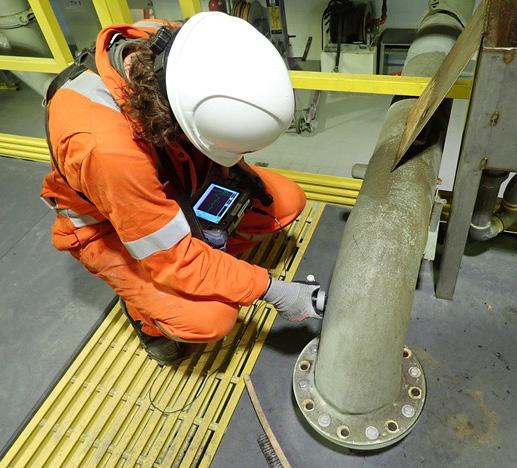
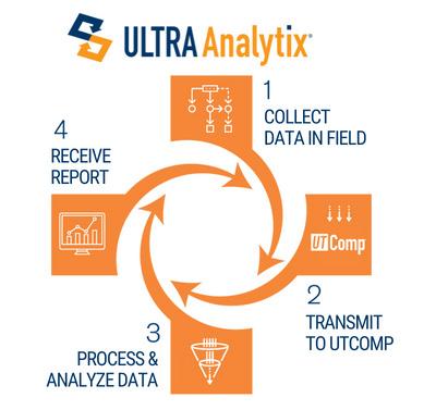
UTComp’s methods for evaluating and monitoring FRP composites are scientifically proven in the lab and in the field. UltraAnalytix results have been validated through academic research and by 500+ comparisons with destructive tests in the field. More than 7000 UltraAnalytix inspections have been carried out for more than 200 companies, including owners of thousands of miles of pipeline infrastructure at petrochemical facilities around the globe.
FRP composite wrap provides fast, effective repairs of steel pipes
Steel pipelines are the safest, most efficient way to transport oil, natural gas and other petroleum products. However, steel is prone to corrosion in harsh environments including desert areas, like the Persian Gulf. The combination of extreme heat, humidity fluctuations, sand and salt, as well as wet hydrogen sulfide (H2S) in the refinery process stream, can cause cracking and leaks in steel pipes.
FRP composite wrap provides a fast, inexpensive and safe alternative to traditional repair methods that include removing and replacing damaged sections of pipe,
Figure 1. UltraAnalytix data collection at a chemical plant in Alberta, Canada. The NDT system combines ultrasonic data collected in the field with external visual inspection and analysis using a proprietary algorithm.
34 World Pipelines / COATINGS & CORROSION 2022
Figure 2. The UltraAnalytix four-step process. Results have been validated through academic research and by 500+ comparisons with destructive tests in the field.
encasing it with a steel sleeve, or welding a patch onto the pipe. The process of dismantling damaged sections of pipe can cause even more damage, and typically requires a partial or temporary shut down of operations.
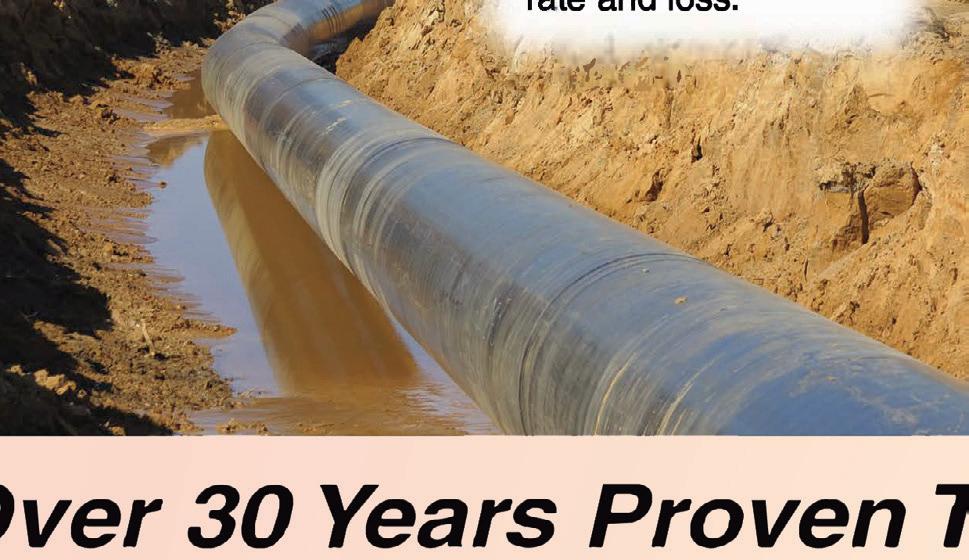


“Hand-wrapping layers of FRP over the damaged area allows for effective temporary repairs that save time and money with minimal downtime, while allowing major repairs to be delayed until the next scheduled maintenance period,” Clarkson says.



“However, because FRP is wrapped by hand, the quality of repairs using this method may be variable and highly dependent on individual workmanship. Done properly, FRP composite wrapping provides leak protection and structural reinforcement that will likely outlast the pipe itself. But regular inspections are essential.”








A better way to evaluate FRP wrap




Recently, a UTComp licensee was asked by a client to provide UltraAnalytix inspection of FRP-wrapped steel pipes at a major petrochemical facility in Saudi Arabia. The pipes, used to carry gasoline and kerosene, had been repaired with an FRP overwrap in 2019 after showing signs of damage from corrosion. The licensee carried out the inspection onsite, and collected ultrasonic data that was sent to UTComp’s engineering team in Canada for analysis and reporting.
In general, it’s important to know two things when inspecting FRP composite reinforcements:
) First, is the overwrap in good condition?
) Second, is the FRP wrap properly bonded to the metal pipe?


“Although we can’t predict the remaining lifespan of the overwrap until the steel pipe itself begins to fail, UltraAnalytix makes it easy to accurately measure the thickness of the wrap and determine the quality of the bond. The system is suitable for inspecting FRP overwraps on a
variety of materials including pipe, structural steel, and even concrete,” Clarkson notes.
For example, UTComp has been monitoring an FRP-wrapped steel pressure vessel at a major chemical plant in the Netherlands for nine years. Clarkson says, without the FRP composite reinforcement, the tank would need to be replaced; but with regular UltraAnalytix inspections the client has been able to extend the life of the tank indefinitely.
Contact factor is key to leak prevention
While wrapping damaged pipe in layers of FRP provides structural reinforcement for added strength, contact factor
(CF) is the more critical measurement for leak protection. CF represents the quality of the bond between the FRP and steel pipe, as well as between the layers of FRP itself. A number of factors can cause defects in CF including: ) Uneven application of resin.
) Contamination by foreign particles.
) Gaps or air pockets between layers of FRP.
) Improper curing due to temperature fluctuations, and other variables that can weaken the bond.
It’s important to note that the correlation between FRP thickness and CF is low. Areas of lower thickness indicates fewer layers of FRP. Thickness provides tensile strength to the FRP, but greater thickness does not correlate with greater leak protection. The quality, integrity and durability of the bond between the initial layer of FRP and the steel is the key to ensuring leak prevention. Therefore, it’s essential to begin repairs by properly preparing the steel surface and following correct lamination techniques throughout.
Repairs to the pipes at the Saudi facility met the ASME PCC-2 standards set out by the American Society of Mechanical Engineers. However, the standard calls for tap testing to identify areas where the FRP isn’t well bonded and doesn’t cover the use of ultrasound to determine CF.
The tap test, or acoustic impact test, is a conventional non-destructive option for evaluating FRP. However, while the tap test is useful, it is also highly subjective and relies entirely on the discerning ear of the person doing the test, Clarkson says.
UltraAnalytix, on the other hand, evaluates FRP thickness and CF with scientific precision. It provides clients with reliable, quantitative data that can be tracked over time to help make the right choices about the quality, performance and lifespan of wrapped pipes and other FRP assets.

Providing ROI and peace of mind
Most UTComp clients gain a return on investment of 10 to 100 times what they pay for an UltraAnalytix inspection.

The UltraAnalytix inspection of the gasoline and kerosene pipes at the Saudi petrochemical facility detected virtually no damage to the polymer in the FRP overwrap. Therefore, the report concluded that the equipment was fit for service, and with regular inspections would likely provide the client with another 30 years of worry-free use. Inspecting their FRP-wrapped pipeline equipment likely saved the client US$20 million in unnecessary repairs and replacement costs.
That type of return makes UltraAnalytix a game-changer for the safe and cost-effective use of FRP assets in oil and gas. It has the potential to save the pipeline industry billions of dollars through regular inspection programmes that prevent leaks and other failures, improve reliability, increase operational uptime and lower capital replacement costs.
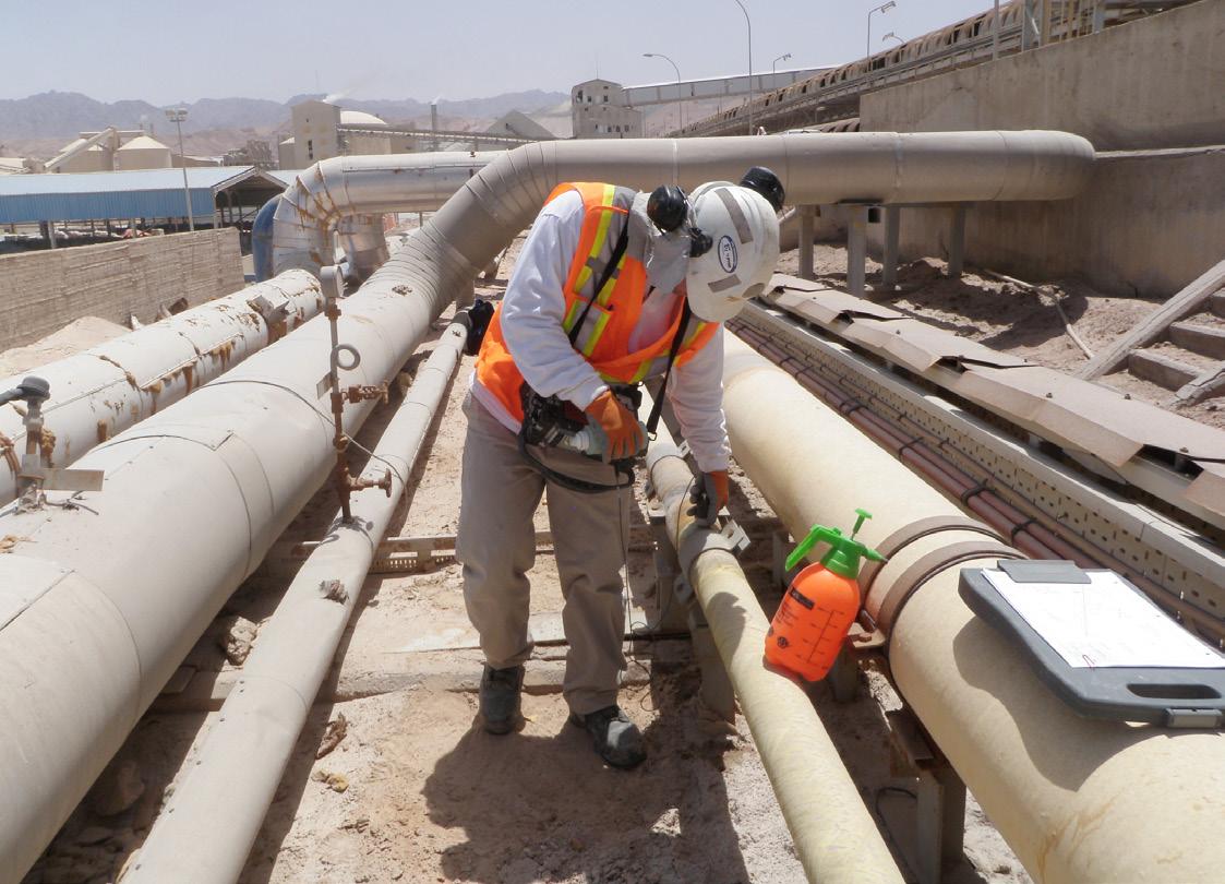 Figure 5. UltraAnalytix inspections have been carried out for more than 200 companies globally, including for owners of thousands of miles of pipeline infrastructure at petrochemical facilities, like this phosphoric acid plant in Jordan.
Figure 4. Taking readings of piping at a phosphoric acid plant in Jordan.
36 World Pipelines / COATINGS & CORROSION 2022
Figure 3. UTComp CTO Geoff Clarkson collects UltraAnalytix NDT data in Portugal.
aterial selection is one of the most fundamental aspects of oil and gas production system design.
A ‘project technical team’, consisting of various industry specialists, will select the optimum materials to satisfy the specific process media and service condition requirements for every scope of work. And the success of a project depends on whether or not they make the right decisions.
For oil and gas projects with process media containing raw aggressive fluids with various combinations of chlorides, CO2 or H2S and other constituents, corrosion resistant alloy (CRA) pipeline materials will typically be the overwhelming choice. Frequently however, obtaining the balance between the CAPEX and the OPEX has proven extremely difficult with the current range of CRA pipeline materials available to the industry.
The choice of which CRA materials to specify requires expert knowledge of both their suitability and their cost effectiveness, since there isn’t any one CRA pipeline material that meets virtually all requirements. That is, perhaps, until now.

Advanced solutions need advanced materials
The N’GENIUS SeriesTM of High Strength Austenitic Stainless Steels represents the total reinvention of conventional austenitic stainless steels – specifically developed to out-perform, supersede and replace the majority of existing grades in the 300 Series.
And whilst the science is complex, the concept is not. With unprecedented strength compared to conventional austenitic stainless steels, vastly improved corrosion resistance and excellent toughness at sub-zero and cryogenic temperatures, engineers can design products with reduced wall thicknesses,
Higher strength and improved corrosion resistance allows engineers to work without compromise, say Dr Ces Roscoe, Paul Harrison and Philip Roscoe, N’GENIUS Materials TechnologyTM, UK.
37
leading to weight savings, an overall reduction in construction and project costs, and a contribution to lower carbon emissions.
The superior corrosion resistance of the N’GENIUS Series also increases the overall lifespan of these projects, reducing long-term maintenance costs and improving environmental sustainability.
Dr Ces Roscoe, CEO N’GENIUS Materials TechnologyTM comments: “Whilst appreciating the enormous strides in the evolution of stainless steels throughout the past century, we wanted to take another look. To think outside the box and invent something with vastly superior engineering design characteristics for the next 100 years.
“From the vast array of products that N’GENIUS can be applied to, our extensive range of CRA line pipe grades is one of the aspects that excites me most of all.”
But most significantly, the N’GENIUS Series provides a comprehensive Series of Alloy Types, Variants and Alloy
Classifications – made available through the N’GENIUS ICONIC SeriesTM and the N’GENIUS INFINITY SeriesTM – that will enable design engineers to satisfy their specific project requirements without compromise.

A vast array of products and applications
The N’GENIUS Series can be manufactured and supplied in a vast array of primary, secondary, engineered and fabricated products across an unlimited number of applications and markets, including seamless line pipe and welded line pipe.
Material data sheets (MDS) have been produced that specify the minimum criteria for the manufacture, inspection, testing and control in accordance with international codes, standards and specifications for each alloy type and variant in the N’GENIUS Series.
These MDS will support end user clients and their nominated engineering consultants, engineering companies and contractors,
38 World Pipelines / COATINGS & CORROSION 2022
Figure 1. N’GENIUSTM engineering design characteristics.
pipe-lay contractors and specialist contractors across the key stages of major projects, from conceptual design stage through to front end engineering stage and detailed engineering stages.
Superior engineering design characteristics
The N’GENIUS Series delivers everything you would expect from leading alloy design technology, and will change the stainless steel industry. It demonstrates superior engineering design characteristics compared to conventional austenitic stainless steels and possesses major technical advantages, as illustrated in Figure 1.
Designed for a longer life
The chemical compositions for the N’GENIUS Series are specified and formulated to achieve distinct minimum pitting resistance equivalent (PREN or PRENW) values for each of the alloy types, variants and alloy classifications. This provides significantly improved resistance to all types of corrosion when compared to conventional austenitic stainless steels.
The N’GENIUS Series also has improved resistance to stress corrosion cracking in certain chloride containing environments, and further increasing the alloying element content leads to an even greater defence against more aggressive and harsher process environments containing specific levels of chlorides, CO2 and H2S.
Furthermore, due to higher strength, a higher alloying element content and a greater resistance to localised corrosion (pitting and crevice corrosion), the N’GENIUS Series also delivers improved resistance to corrosion fatigue.
It is perhaps difficult to imagine an innovation that combines all the key attributes and design characteristics that the N’GENIUS Series possesses. These features, along with the added potential to reduce overall project costs whilst sustaining the design life of products, is a powerful combination in itself.
For CRA materials, this is so much more than just a ‘pipedream’, if you’ll pardon the pun.
Extensive range of CRA line pipe grades
An extensive range of CRA seamless and welded line pipe grades has been developed that will fundamentally change the materials selection philosophy for projects throughout the world. A small sample of the N’GENIUS Series CRA line pipe grades are shown in Figure 2.
In addition to those alloy types and grades of CRA line pipe listed in Figure 2, there are numerous other alloy types and grades of CRA line pipe in the N’GENIUS ICONIC series of high strength austenitic stainless steels, ranging between N’GENIUS ICONIC 17Cr-HSA and 29Cr-HSA.
Furthermore, an extensive range of alloy types and grades of CRA line pipe in the N’GENIUS INFINITY series of high strength austenitic stainless steels has also been developed to satisfy an even wider range of service conditions and process media environments experienced in major projects throughout the world.
The N’GENIUS INFINITY Series includes variants for each of the alloy types which contain different levels of other alloying elements at predetermined levels or ranges, such as copper and tungsten. The N’GENIUS INFINITY Series is formulated to
achieve distinct minimum specified levels of pitting resistance equivalent PREN = % Cr + 3.3 x % Mo + 16 x % N or PRENW = % Cr + 3.3 x (% Mo + % W) + 16 x % N for each variant of the alloy types and alloy classifications, and these can be tailored to satisfy bespoke test conditions and process media environments of any specific project requirements.
The chemical compositions and microstructures for each variant of the alloy types and alloy classifications are even further optimised within the chemical analysis range to achieve a unique combination of mechanical and corrosion resistance properties.
This ensures that the N’GENIUS INFINITY Series has even further improved resistance to localised corrosion (pitting corrosion and crevice corrosion), intergranular corrosion as well as general corrosion in an extremely wide range of process environments when compared to conventional austenitic stainless steels.
As the alloying element content increases throughout the N’GENIUS ICONIC Series and N’GENIUS INFINITY Series, the minimum pitting resistance equivalent (PREN or PRENW) values increase to specific minimum levels for alloy type and each variant of the alloy types.
What is clear, is that the N’GENIUS Series is a complete ‘family’ of high strength austenitic stainless steels.
No more compromise
Currently, the API 5LC specification for CRA line pipe contains only one conventional low strength austenitic stainless steel grade (LC30-1812), one martensitic stainless steel grade (LC52-1200), two duplex stainless steel grades (LC65-2205 and LC65-2506) and three super-duplex stainless steel grades (LC80-2507). (As an interesting aside, the original super-duplex stainless steel grade S32760 was also invented by Dr C V Roscoe).
The DNVGL-ST-F101 Offshore standard for submarine pipelines is even more limited, containing two martensitic stainless steel grades (DNV 550 13 Cr-2Mo and DNV 550 13 Cr-2.5Mo), one duplex stainless steel grade (DNV-450 22Cr) and one super-duplex stainless steel grade (DNV-550 2507).
Despite being mentioned in the DNVGL-ST-F101 offshore standard, conventional low strength austenitic stainless steel line pipe is not even referenced in the tables of chemical composition and mechanical properties.
As such, the CRA line pipe grades currently listed in the API 5LC specification for CRA line pipe and the DNVGL-ST-F101 offshore standard are extremely limited. Their suitability, particularly for subsea pipelines, is somewhat restricted when considering certain factors, including resistance to general corrosion; localised corrosion (pitting and crevice corrosion); stress corrosion cracking and hydrogen embrittlement; fracture toughness linked to microstructural issues at ambient temperatures or low and sub-zero temperatures; suitability for offshore welding and fabrication; and various pipeline installation methods such as reel-lay, S-lay and J-lay.
In view of this limited choice, engineers frequently find themselves having to compromise on their ideal material selection, particularly when taking cognisance of the optimum combination of mechanical properties and corrosion resistance requirements for the service conditions and process media environments for their specific projects. The ‘project technical team’ must ensure
COATINGS & CORROSION 2022 / World Pipelines 39
that the overall requirements of the projects are satisfied, whilst project management need to ensure that costs are controlled within budget and that deadlines are strictly maintained.
There is a need for a much wider selection of CRA line pipe grades in shallow waters where the service conditions and process media environments contain chlorides and CO2. But that limited availability is even more problematic in deepwater and ultra-deep water environments, high pressure, high temperature (HPHT) service conditions and more aggressive process media environments containing much higher levels of chlorides, CO2 and H2S and other constituents resulting in lower pH levels of the process media.
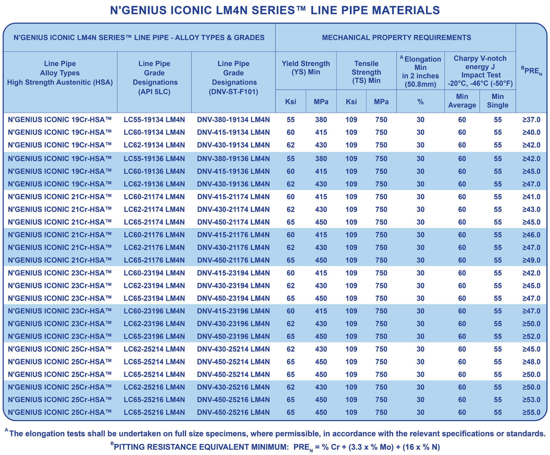
The presence of these contaminants can promote general corrosion, localised corrosion (pitting and crevice corrosion), stress corrosion cracking and hydrogen embrittlement issues, which can initiate different types of corrosion failure mechanisms. This can then lead to premature failure of a pipeline, particularly if the availability of suitable CRA line pipe grades is limited, if the pipe manufacturing processes have not been properly controlled, or
if there are excursions in the service conditions or process media environment throughout the life of the field.
Everybody wins, even the planet And as we balance working in the harshest environments with a need to protect that environment, improve through-life costs and safeguard our people, the N’GENIUS Series of high strength austenitic stainless steels may well prove a key technology –satisfying the growing demand for materials that are stronger, last longer and are better for the planet.
The extensive range of the N’GENIUS Series is a major leap forward in line pipe technology. For the first time ‘project technical teams’ can select and specify the optimum corrosion resistance alloy from the extensive range of N’GENIUS Series line pipe grades for all major projects, without the need for any compromise.
The N’GENIUS Series can be produced by Premier manufacturers of stainless steel under license from N’GENIUS Materials Technology or its sister company, United Pipelines.
40 World Pipelines / COATINGS & CORROSION 2022
Figure 2. CRA line pipe grades.
Dr. Adam Jackson, Technology Manager, Vipo, Norway, discusses the rubber materials that have been used in subsea thermal insulation, and outlines the vulcanisation process. hermal insulation of subsea pipelines and structures has been a vital tool in the flow assurance world, offering a means of providing predictable and reliable thermal performance over the lifetime of oil and gas fields. Over time, products have been refined regarding thermal performance, depth, temperature capability, deployment, and operation. Today’s products have generally been field-proven, in some cases for decades, and their robustness is without question within their qualified performance envelopes. The introduction of the ISO 12736 standard has given much stability to the qualification process, as it prescribes a number of tests on both materials and systems, which prove suitability
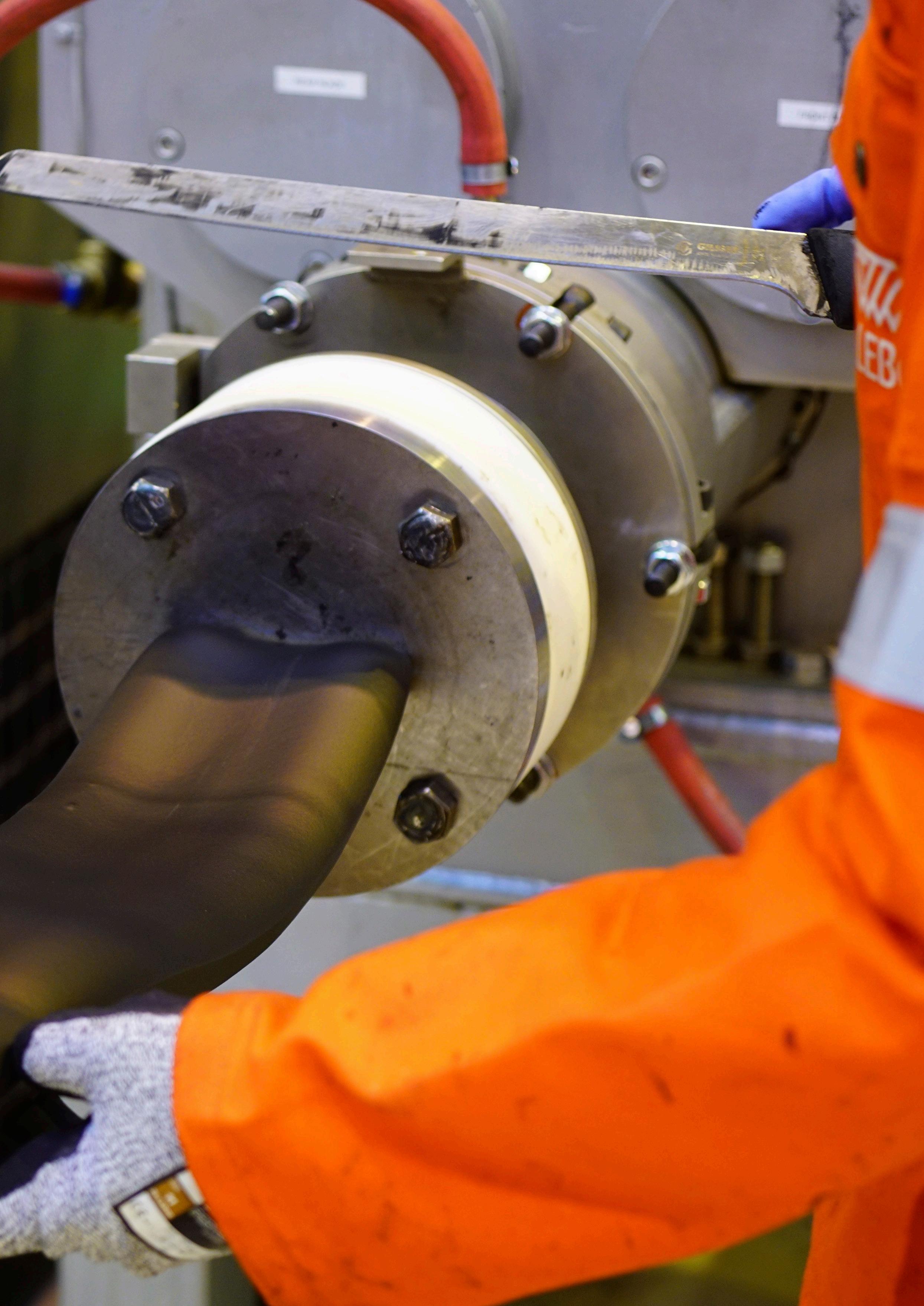
41
Figure 1. Vikotherm R3 profile extrusion.
and generate data that is of great importance in the insulation design process.

Market trends
Over time, the thermal and mechanical performance requirements placed on thermal insulation systems have become steadily more demanding. The 300 m, 90˚C dream of the 1980s and mid 1990s is now considered to be mild service, being replaced with the current desire of 3000 m and 180˚C. At such temperatures, many of the incumbent materials are no longer suitable, either due to melting or inadequate long-term performance in the marine environment. Many other materials that could withstand the hydrothermal load over time are too expensive, difficult to process, or not compatible with those techniques and steps used in fabrication and deployment.
Rubber technology in general
Rubber materials have been used in subsea thermal insulation systems for 50 years, and have proven performance. The variety of materials available is vast (Figure 2), although most of the systems available are based on polychloroprene (1), butyl rubber (2) nitrile rubber (3) and hydrogenated nitrile rubber (4) and ethylene propylene rubber (5).
Rubbers are convenient materials to handle and apply, as hand applied systems on either blasted and primed steel, or onto suitable abraded anti-corrosion coating. These materials do not require moulds or high temperatures for application, unlike fluid or melt processed systems. This shortens lead time and gives a quick onsite mobilisation. These materials
are conveniently applied using simple hand tools, which also reduces the footprint of the process. Overall application rates are very competitive with other available systems, when mobilisation of moulds, sealing of moulds, pumping time and their removal post casting are considered.
One of the aspects of rubber technology which has hampered wider use is the vulcanisation step. The reason for this having been a hinderance is threefold.
) Vulcanisation processes have historically required components to be placed in an autoclave, which is not possible in many cases due to the size of the workpiece or the lack of an autoclave close to the client’s preferred application site.
) The vulcanisation step generally takes some considerable time as the applied coating is often quite thick. Multistep vulcanisation for very thick materials can lead to long overall application times.
) Vulcanisation has required the use of high temperatures (120˚C and above) for extended periods of time.
Curing of rubber – vulcanisation
Vulcanisation is a process where unsaturated bonds or labile atoms within the raw resin are used to form crosslinks between adjacent polymer chains. The formation of these bonds is dependent on many factors, but from a practical and operational viewpoint, this can be reduced to temperature needed to initiate and drive the chemical reaction to completion. As with catalysts in epoxy and urethane systems, the cross-linking reaction is enabled by the use of a vulcanisation package. This can be a simple single component but is often a complex mixture of agents.

Considerable focus has been dedicated to the development of low temperature vulcanisation, and vulcanisation packages have been developed to allow reliable cross-linking as low as 50˚C. These systems do not require the use of an autoclave and can be cured using hot air, heating laces or similar convenient heating sources.
Other material considerations
When rubber coating items, it is important that the material also has sufficient ability to merge, coalesce and bond to itself and the substrate. This property, known as ‘tack’, must be optimised as part of the product development process. In addition to the material’s tackiness, the vulcanisation package must allow for the flow and merging process in the initial heating stage of the cross-linking and a period known as the ‘scorch time’ must be long enough to allow application and flow. A good combination of scorch time and tack is important for product uniformity and integrity. These new formulations have an excellent balance of tack and scorch time, giving a fully coalesces product following vulcanisation.
The material’s tendency to exhibit elastic properties, even in the uncured state, has to be considered for hand application purposes. It is important that this aspect, known as ‘nerve’, is as low as possible, but without sagging. Materials with excessive nerve tend to recoil. This creates
potential
Figure 2. Typical chemical structures of commercial rubbers.
42 World Pipelines / COATINGS & CORROSION 2022
Figure 3. Typical coating for wellhead tree.


Need a reprint? +44 (0)1252 718999 reprints@worldpipelines.com We can tailor to your requirements, produce 1 - 12 page formats, print colour or mono and more
problems with merging of materials, maintaining contact with substrates and the formation of complex geometries. The new formulations have low nerve.
Low temperature vulcanising formulations
Formulations of low temperature vulcanisable rubber have been developed. These materials eliminate those hurdles that have limited the penetration of rubber systems into the subsea thermal insulation market.
Commercially available formulations are now accessible, which have the capability of providing a high level of reliable insulation at temperatures up to 180˚C at the full 3000 m water depth.1 These systems have been thoroughly tested and qualified in accordance with ISO 12736, and have established track record.
These materials are conveniently delivered to site as a two-component system for blending and extrusion to profiles, or as pre-extruded strip stock in refrigerated containers. The materials are readily applied to blasted and primed steel, or to a suitably abraded anti-corrosion coating using simple hand tools. Simultaneous application and vulcanisation is possible due to the low vulcanisation temperature, removing the wait time between application layers and speeding up the overall coating process. Low temperature vulcanisation removes the need for autoclaves and the flow-cure characteristics of the materials gives a fully coalesced product.
Considering site application, these new formulations give:
) Rapid site mobilisation with no requirement for up-front engineering.
) High application rate.
) Small footprint of necessary equipment.
) Low temperature vulcanisation without autoclave.
) Low threshold for training of local applicators.
For the end user:
) Low thermal conductivity.
) High heat capacity.
) Hydrothermally stable at in excess of 180˚C.
) Water depth capability in excess of 3000 m.
) Highly resilient and robust system.

) Fully qualified in accordance with ISO 12736.
Rubber based thermal insulation systems present a viable and efficient path for realising highly robust and efficient thermal insulation systems on a wide range of structures and peripheral equipment.
References
1. Vikotherm® R3.
fforts have been made in the development of high strength steels that have led to significant improvements to pipeline projects in cost reduction while increasing allowable operating pressures. In addition, the use of high strength steels a llowed for reduced pipe wall thickness (WT), which has resulted in less material, i.e. weight, shipping and welding costs. These developments have improved the toughness properties of the steel, as well as the weldability, even under field and other conditions. This has resulted in the reduction of pipe construction costs, especially with respect to shipping, and reduced welding times for thinner WT. Because it can be difficult to prevent external corrosion on pipeline steels, controlling the corrosion rate using coating and cathodic protection (CP) is the most economical solution. Increasing the WT is another solution; however, it would negate or offset some of the gains that were developed with high strength pipeline steels and associated costs.
The problem
Because of the lack of extra or additional corrosion allowance as with the older, heavier wall pipe, we must better identify the mechanisms of corrosion and the methods of arresting corrosion processes. There are many forms of corrosion. However, there are two primary methods of slowing the corrosion process down to a manageable/safe level to meet industry standards and regulatory requirements. Coatings and CP work well together for underground or submerged pipeline systems. The following is an overview of coatings and CP: ) Coatings are the first line of defence against external corrosion.
) Coatings are not perfect and must be cathodically protected to slow down the corrosion rate at breaks (holidays).
) CP is applied to underground and submerged structures to prevent corrosion of the steel substrate at holidays.
) Coatings such as fusion bonded epoxies (FBE) allow CP through micro-pores.
• 0.356 mm (14 mil) coating thickness is common for line pipe.
• 0.508 mm (20 mil) coating thickness is common for horizontal directionally drilled (HDD) crossings.
) Coating types play an important role in the CP of the pipeline.
) CP is used to protect only the exposed metal substrate at small holidays.
) Smaller holidays reduce the size and high expense of operating CP systems.

) A well-designed coated structure will ensure good current attenuation with protection against corrosive forces over the life of the pipeline.
There are many physical and chemical properties required for a good line pipe coating according to AMPP. They are as follows:
) An effective electrical insulator.
) An effective moisture barrier.
) Can be applied to the pipe by a method that does not adversely affect the properties of the pipe.
) Can be applied to piping with a minimum of coating defects.
) Good adhesion to pipe surface.
) Ability to resist development of holidays with time.
) Ability to resist damage during handling, storage, and installation.

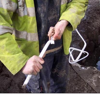
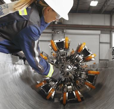
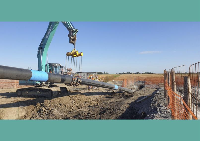







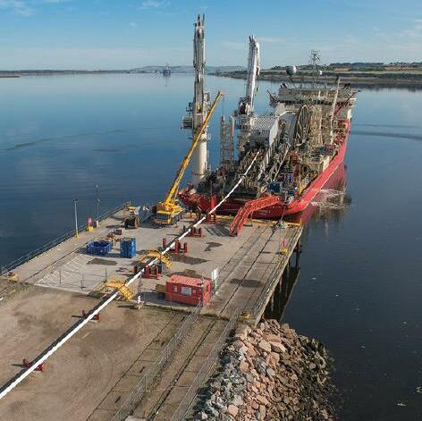





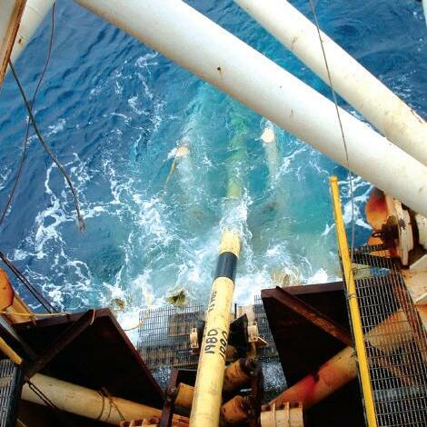
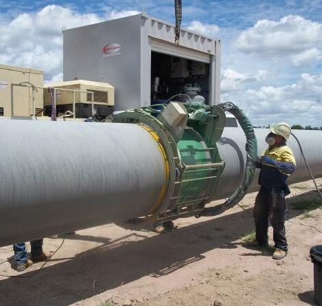
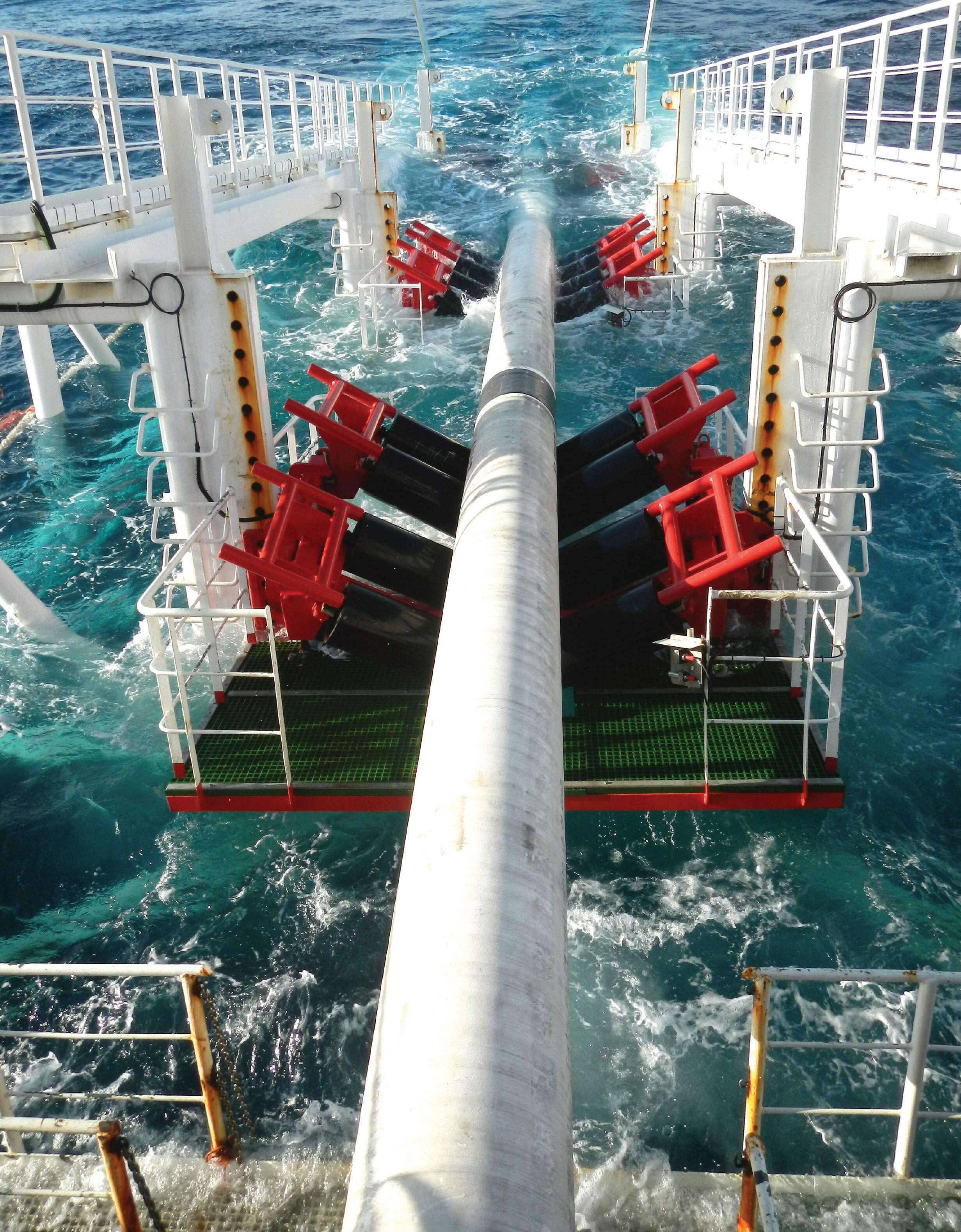
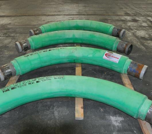


 Figure 3. Side booms lowering pipe into a ditch.
Figure 2. US petroleum liquids pipeline projects (2010 - 2021). (Source: US Energy Information Administration Liquids Pipeline Projects Database)

 Figure 5. Epoxy/polyurethane girth weld coating, SP-2888 RG, on HDD pipe.


 Rogelio Guajardo, Head of Analysis UC, NDT Global, Germany, talks about detecting, sizing, and characterising challenging crack features.


 Dr. Christopher O’Connor, Principal Consultant of Energy Systems, DNV, UK, talks assuring the integrity and efficient maintenance of 21st Century PE100 hydrogen and methane gas pipelines.


 Figure 1. Molecular mixing of molecules during fusion.
Figure 2. Failure modes of PE100 pipe – internal hydrostatic pressure testing.
Figure 3. Ductile failure of PE100 pipe.


 Figure 5. UltraAnalytix inspections have been carried out for more than 200 companies globally, including for owners of thousands of miles of pipeline infrastructure at petrochemical facilities, like this phosphoric acid plant in Jordan.
Figure 4. Taking readings of piping at a phosphoric acid plant in Jordan.


