Brent McAdams, OleumTech Corp., explores the role of automation and digitalisation in the oil and gas sector, discussing their applications, benefits, challenges, and potential to revolutionise the industry in the future.
07 Future-proofing the workforce
Lynn Coutts, Managing Director – the Middle East, ATPI, explains how the oil and gas industry can balance efficiency with workforce wellbeing, through digitalisation and optimised crew management.
11 The digital evolution of an energy ecosystem
Per Erik Holsten, President of ABB’s Energy Industries division, provides insight into how digitalisation is the next evolution of automation in the energy ecosystem.
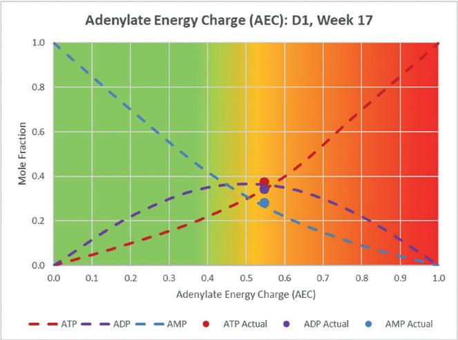
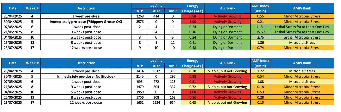
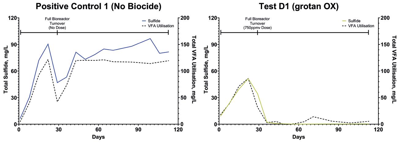
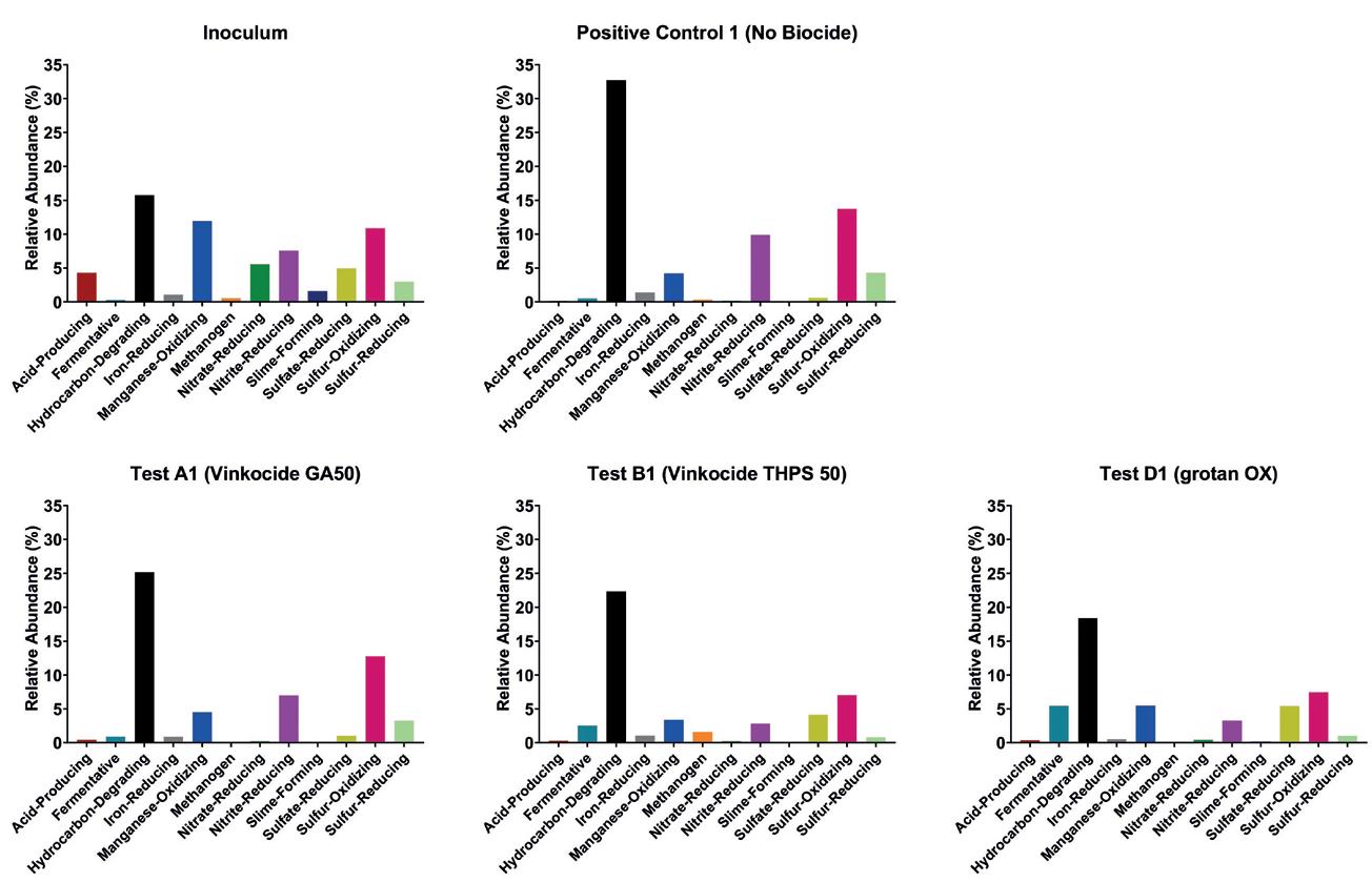
Vink Chemicals presents the longterm performance of its biocide grotan® OX in controlling oilfield souring. In an extended bioreactor study, grotan® OX sustained metabolic suppression, prevented biogenic H₂S regeneration, and outperformed conventional chemistries. The results position grotan® OX as a durable, remedial and preventative solution for effective biogenic souring control in challenging oilfield environments.
21 AI-powered insights
Gary Hickin and Jessica Stump, NOV, discuss how AI-powered insights can enhance real-time decision-making and drilling performance.
24 Maintaining floating asset integrity
Danny Constantinis, EM&I, Malta, addresses methods of maintaining the integrity of Floating Production Units (FPUs) and Floating Production, Storage, and Offloading (FPSO) assets.
29 A customisable approach
Nasraldin Alarbi, Senior Product Champion – Cementing, and Afshin Ahmady, Technical Advisor – Cementing, Halliburton, discuss how customised design approach reduces the risk of uncertainty in lost circulation control.
33 Risk mitigation: Scaling back challenges
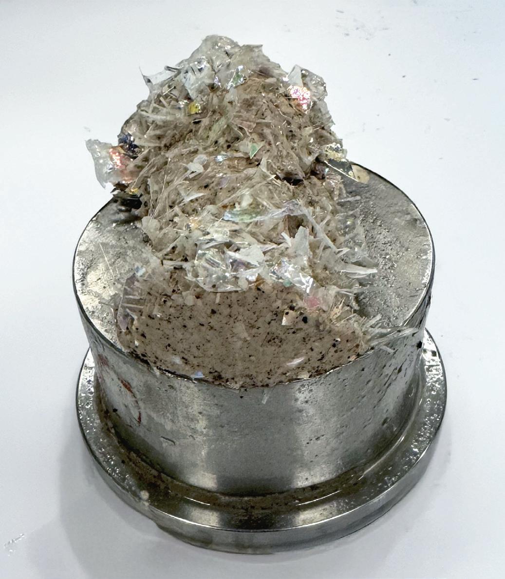
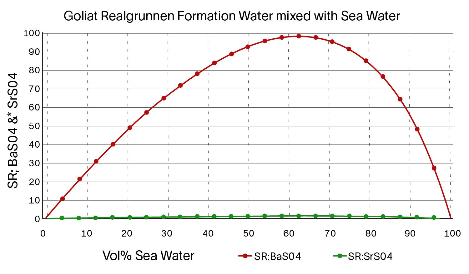
Kim Vikshåland, ChampionX, explains how the risks were mitigated through the identification and optimisation of appropriate chemical treatments for scale inhibition via topside, subsea and squeeze applications.
37 Silence the sour
Matthew Snape and Jennifer Knopf, Vink Chemicals, and Matt Streets, Rawwater, discuss long term preservative biocides for biogenic souring control.
41 Sampling for success
Eric Kvarda, Principal Applications Engineer, Swagelok, details how by eliminating unnecessary complexities, potential leak points, and excessive maintenance requirements, a standardised plan for sampling points can save oil and gas operations millions.
44 Navigating the complex reality of decommissioning
Richard Vann, RVA Group, explores the region’s complex decommissioning demands and highlights the critical steps required to navigate them safely, as the Middle East’s legacy oil and gas assets face retirement.
Still pioneers.
Across energy and critical infrastructure, we bring expertise where complexity is highest, partnering with globally local teams and leveraging unrivalled proprietary technologies. Like the M-500 Single Torch External Welding System, seamlessly integrated with Data 360 our cloud-based digital platform that analyses, and visualises your project performance data in real time. We move projects forward, no matter the challenge. We’re here to partner on how our specialist welding and coating solutions can help you power tomorrow.
World news
September/October
2025
AI-powered analysis reveals oil industry’s trillion-barrel opportunity in
existing fields
The oil industry possesses a trillion-barrel opportunity within existing fields that could meet global demand through 2050 without major new discoveries, according to groundbreaking analysis from Wood Mackenzie.
“The oil industry’s challenge is enormous,” said Andrew Latham, SVP Energy Research at Wood Mackenzie. “Total liquids demand under our base-case Energy Transition Outlook scenario is just less than 1 trillion bbls through 2050. Without upgrades to current development plans, today’s onstream fields are set to fall short by almost 300 billion bbls. This deficit would grow by another 50 billion bbls under our delayed transition scenario.”
Wood Mackenzie’s proprietary Synoptic AI-powered analysis of oilfield performance shows existing fields are far from exhausted. The new AI-powered Analogues feature enables efficient, unbiased assessment of Wood Mackenzie’s already industry-leading data to deliver previously overlooked insights into recovery upside.
In one of the first deployments of the Analogues feature, it was revealed that better recovery from producing fields could yield an additional 470 billion to over 1000 billion bbls. This potential only requires the application of established best practices already deployed successfully across the industry, not unproven technologies.
Using proprietary data on reservoir geology, hydrocarbon quality, in-place resources, operator access to finance and technology, costs and fiscal terms, Wood Mackenzie estimates upside oil recovery factors. The analysis examined over 30 000 fields worldwide using machine learning to identify similar analogues across 60+ parameters.
The research reveals that national oil companies (NOCs) and state-controlled enterprises operate fields containing more than 320 billion bbls of upside potential if top-quartile recovery factor is achieved and 700 billion barrels on a best-in-class recovery basis – representing almost 70% of the global opportunity.
Iran, Venezuela, Iraq, and Russia stand out with the largest recovery upside potential of any countries. By contrast, major international oil companies, despite operating above-average quality fields, control just 6% of global upside potential due to their already strong performance levels.
bp approves Tiber-Guadalupe project in the Gulf of Mexico
bp has reached a final investment decision on the Tiber-Guadalupe project in the Gulf of Mexico, approving its second new production platform in less than two years in the critical US offshore region and further underscoring the significance of the US Gulf to its global strategy.
The 100% bp-owned Tiber-Guadalupe will be bp’s seventh operated oil and gas production hub in the Gulf of Mexico, featuring a new floating production platform with the capacity to produce 80 000 bpd of crude oil. The project includes six wells in the Tiber field and a two well tieback from the Guadalupe field. Production is expected to start in 2030.
“Our decision to move forward on the Tiber-Guadalupe project is a testament to our commitment to continue investing in the Gulf of America and expand our energy production from one of the premier basins in the world,” said Andy Krieger, bp’s Senior Vice President, Gulf of America and Canada. “Along with its sister project Kaskida, Tiber-Guadalupe will play a critical role in bp’s focus on delivering secure and reliable energy the world needs today and tomorrow.” Tiber and Guadalupe fields are estimated to have recoverable resources of around 350 million boe from the initial phase.
The estimated US$5 billion Tiber-Guadalupe project is fully accommodated within bp’s disciplined financial framework. It is one of the 8 - 10 major projects expected to start up globally between 2028 and 2030 and reflects bp’s strategy to grow its upstream business and long-term shareholder value. Together with its 100% bp-owned Kaskida project, bp expects to invest around US$10 billion to deliver its Gulf of Mexico Paleogene projects.
Tiber-Guadalupe and Kaskida are centrepieces of bp’s new build projects in the deepwater Gulf of Mexico. Along with the five existing operating platforms in the Gulf, they will help enable bp to boost its capacity to produce more than 400 000 boe/d from the US offshore region by 2030. bp aims to increase its offshore and onshore production in the United States to more than 1 million boe/d by 2030.
Liberia
TotalEnergies has signed four Production Sharing Contracts (PSC) for the LB-6, LB-11, LB-17 and LB-29 Exploration blocks offshore Liberia, which were awarded following the 2024 Direct Negotiation Licensing Round organised by the Liberia Petroleum Regulatory Agency.
Alaska
Pantheon Resources plc has announced that hydraulic fracture stimulation of the Dubhe-1 well on Alaska’s North Slope is scheduled to begin the week of 29 September, taking about two weeks, with production testing to follow using a temporary system.
São Tomé and Príncipe
Petrobras has concluded the acquisition of a 27.5% stake in Block 4, located in São Tomé and Príncipe, Africa. With this acquisition, Petrobras joins the consortium of the aforementioned block, which includes Shell, the operator of the asset (30%), as well as Galp (27.5%) and ANP-STP (15%).
Egypt
Egypt has entered into four oil and gas exploration agreements with international companies valued at more than US$340 million, aiming to bolster domestic production in the face of growing energy demand. The agreements encompass offshore blocks in the Mediterranean and Nile Delta.
North Sea
Equinor and partners have struck oil and gas in the Fram area, 9 km north of the Troll field in the North Sea. In total, the resources are estimated at between 0.1 and 1.1 million m3. The reservoir properties are assessed as moderate to very good. The preliminary name of the discovery is F-South.
World news
September/October
TechnipFMC awarded significant subsea production systems contract by Petrobras
20 - 22 October 2025
SPE ATCE 2025
Houston, USA
https://www.atce.org/
3 - 6 November 2025
ADIPEC 2025
Abu Dhabi, UAE
https://www.adipec.com/visit/ registration
4 - 5 February 2026
Subsea Expo Aberdeen, UK https://www.subseaexpo.com/
10 - 11 March 2026
StocExpo 2026
Rotterdam, Netherlands
https://www.stocexpo.com/en/
Diary dates Web news highlights
Ì WellSense sells FiberLine Intervention licence to an oilfield service company
Ì Aker BP and FourPhase deliver industry-first remote solids management project in the North Sea
Ì Motive acquires Weld Integrity, a leading Norway-based inspection and testing business
Ì Expro launches remote clamp installation system in North Sea
Ì Kurita America and Cyclopure to deliver groundbreaking PFAS removal and regeneration solutions
Ì KBC launches Maximus 7.6 to close the gap between models and upstream operations
To read more about these articles and for more event listings go to:
www.oilfieldtechnology.com
TechnipFMC has been awarded a significant contract, following a competitive tendering process, for subsea production systems by Petrobras. TechnipFMC will design, engineer, and manufacture subsea production systems to be deployed in an array of greenfield developments, brownfield expansions, and asset revitalisations across Petrobras’ extensive portfolio. The contract also covers installation support and life-offield services, with provisions for additional equipment and services.
Jonathan Landes, President, Subsea at TechnipFMC, commented: “Leveraging our industrialised operating model, we can standardise innovative solutions and deliver the schedule certainty that Petrobras expects on its projects. We look forward to creating new value together as we build on our decades-long relationship as a trusted local partner.”
The subsea production systems will be manufactured and serviced in Brazil, utilising local capabilities and expertise.
Aquaterra Energy wins subsea analysis contracts in Indonesia
Aquaterra Energy has secured multiple offshore analysis contracts with INPEX Masela, LTD., a subsidiary of INPEX Corporation, Japan’s largest oil and gas exploration and production company. The work will support upcoming subsea drilling campaigns offshore of Indonesia.
Under the contract, Aquaterra Energy will deliver multi-phase conductor and riser analysis for a series of deepwater wells in water depths ranging from 600 - 800 m, providing technical input to support decisionmaking at the earliest stages of project development.
The scopes of work, awarded following competitive tender, include structural analysis and the definition of operating envelopes, technical limits covering weather conditions, rig movement and fatigue. These inputs will help shape INPEX’s planning process, including considerations such as rig selection and equipment specification. Aquaterra’s early involvement will play a key role in helping define safe operating limits, giving INPEX greater confidence in its technical planning ahead of drilling.
Expro sets offshore World Record
Expro has achieved a world record by deploying the heaviest casing string to date, using its advanced Blackhawk® Gen III Wireless Top Drive Cement Head with SKYHOOK® technology. The record was achieved on a significant project in the Gulf of America for a super major.
The operation, conducted aboard the Transocean Deepwater Titan – an eighth generation ultradeepwater drillship – set a new benchmark in deepwater well construction. With a maximum hook load of 2.849 million lb, the casing deployment exceeded all prior offshore records.
IEA forecasts rapid rise in global oil supply
The International Energy Agency (IEA) has indicated that global oil supply is set to increase more swiftly this year, with a surplus potentially growing by 2026. This is due to both OPEC+ members boosting their output and the growth of supply from non-OPEC+ countries.
The IEA, which provides guidance to industrialised nations, noted a projected supply rise of 2.7 million bpd to 105.8 million bpd by 2025, and an additional increase of 2.1 million bpd to 107.9 million bpd the following year. The OPEC+ group, comprising the eight countries of Algeria, Kazakhstan, Kuwait, Iraq, Oman, Russia, Saudi Arabia and the United Arab Emirates, has agreed to augment its production.
Following a decision on 7 September to commence unwinding its second tranche of supply cuts, the group plans to elevate its output target by 137 000 bpd in October. At this rate, it would take one year to fully implement the 1.65 million bpd tranche of cuts, leaving 2 million bpd of cuts still in place.
The IEA’s analysis suggests that supply is increasing much faster than demand, even though it has revised its global demand growth forecast this year to 740 000 bpd, highlighting strong deliveries in advanced economies.
BRADEN has proudly set the industry standard for safety and performance in offshore crane applications. Engineered to deliver unmatched durability and precise load control, BRADEN hoists are backed by world-class training and support, making them the preferred choice for equipment manufacturers and operators who prioritize safety. BRADEN hoists meet or exceed all required safety and environmental standards for offshore use, including personnel handling.
www.arrowheadwinch.com
September/October 2025
Contact us
Editorial
Managing Editor: James Little james.little@oilfieldtechnology.com
Senior Editor: Elizabeth Corner elizabeth.corner@oilfieldtechnology.com
Design
Production Designer: Iona MacLeod iona.macleod@oilfieldtechnology.com
Production Manager: Kyla Waller kyla.waller@oilfieldtechnology.com
Sales
Sales Director: Rod Hardy rod.hardy@oilfieldtechnology.com
Sales Manager: Chris Lethbridge chris.lethbridge@oilfieldtechnology.com
Sales Executive: Daniel Farr daniel.farr@oilfieldtechnology.com
Events
Head of Events: Louise Cameron louise.cameron@oilfieldtechnology.com
In 1896, Eunice Foot identified that increasing CO2 could warm the Earth’s climate. In 1896, Svante Arrhenius calculated the potential warming from CO2 emissions created by mankind. And in 1938, Guy Callendar presented evidence to link fossil-fuel driven CO2 emissions with the rising temperature of the Earth. It was not until the 1980s that this discussion entered the political arena – and now, net zero is one of the most heavily debated topics among scientists, politicians, and industry professionals alike.
The Intergovernmental Panel on Climate Change (IPCC) was formed in 1988, with the purpose of providing policymakers with regular scientific assessments on climate change, its implications, and potential future risks, as well as to put forward adaptation and mitigation options.1 For the oil and gas sector, this would represent a slow but not insignificant turn in the trajectory of the industry. Initially, it was a subtle recognition that burning of fossil fuels increased greenhouse gas (GHG) emissions. This led into greater policy pressure and regulatory risk culminating in climate agreements such as the 2015 Paris Agreement. The sector was facing greater restrictions and public/investor scrutiny was on the rise as a result. Despite some scepticism, climate concerns were not to be downplayed. The experimentation with renewables conducted by oil majors such as Shell and bp was certainly evidence for change. It was the cumulative weight of the IPCC that lead to major players adopting the net-zero pledges that we see in action today.
The pledge for net zero – whether it be by 2030, 2050, or beyond – is certainly at the forefront of development within the oil and gas industry at the moment. Wasteful industry operations in the oil and gas sector contributed to nearly 80 million t of methane leaked in 2023.2 The IEA’s Global Tracker report noted that the fossil fuel sector accounts for approximately 85% of the global methane emissions from human activity. Upstream sources include all emissions from production, gathering, and processing at both onshore and offshore facilities. As a result of this, countries have developed policies and regulations as a form of mitigation. This includes national cap-and-trade systems (Canada), policies that promote decarbonisation and minimisation of flaring/routine flaring operations (Brazil), and regulations that introduce mandatory requirements for emissions at source level (EU) – all with the aim to minimise methane emissions.3
To combat this growing issue, there has been a drive for new, innovative methods to decrease methane emissions. Notable is the collaboration between ExxonMobil Corp. and GHGSat, to monitor and mitigate methane at scale across ExxonMobil’s onshore operations in North America and Asia, including the US, Canada, Papua New Guinea, and Indonesia. This form of satellitebased emissions monitoring helps pinpoint the source of methane leaks. Other popular methods being utilised include drone-based sensors like those utilised by Equinor on the Norwegian Continental Shelf, and Saudi Aramco’s utilisation of AI-enabled leak detection using mobile sensors on pipelines in the Middle East.
This issue of Oilfield Technology has a regional report from ATPI on supporting the oil and gas workforce in the Middle East, as well as features on Digitalisation and Automation, Decommissioning and Asset Retirement, Production Monitoring, and much more!
Future-proofing the workforce Future-proofing the workforce
Lynn Coutts, Managing Director –the Middle East, ATPI, explains how the oil and gas industry can balance efficiency with workforce wellbeing, through digitalisation and optimised crew management.
or decades, the oil and gas industry has been the foundation of economic growth across the Middle East. The region has developed into a global energy hub, driving supply, shaping geopolitics, and fuelling development far beyond its own borders. Even as the industry adapts to digitalisation, new energy mixes, and a rapidly shifting global market, one reality remains unchanged: oil and gas will always be there. The question is not whether it will endure, but how the industry can continue to meet rising expectations.
Today, the challenge is defined by constant pressure to do everything cheaper, better, and faster. Investors and governments want maximum efficiency. Operators want higher productivity.
Customers expect lower costs. Yet none of these goals can come at the expense of the workforce, whose safety and wellbeing remain paramount. Striking the right balance between operational efficiency and human care is more complex in the Middle East – a region that presents unique requirements unlike any other oil and gas region in the world.
The Middle East’s dynamic workforce requirements
Unlike the North Sea or North America, the Middle East depends heavily on an expatriate workforce. Thousands of engineers, technicians, and support staff travel from multiple countries across the globe, often on rotating schedules, creating vast logistical networks that must operate with extraordinary precision. In addition, this workforce faces geopolitical volatility, extreme heat, long shifts, and extended periods away from families, and the human element becomes just as critical as physical safety. These challenges unfold against the backdrop of multi-billion-dollar mega-projects, where even minor delays or inefficiencies can result in significant financial and reputational costs.
To succeed, companies are rethinking how they manage people, travel, and processes. They are optimising workflows, streamlining approvals, and integrating technology so that crew changes, project rotations, and emergency responses can happen seamlessly and cost-effectively. Crucially, the sector is embracing a cultural shift: recognising that future-proofing the oil and gas industry is as much about protecting people as it is about managing assets.
Technology as an enabler
Just as digital platforms and processes are transforming the exploration production process, so too are they changing the way businesses think about how to manage crews and personnel. Finding the right harmony between optimising production and looking after people is made a lot easier in an era of digital revolution.
As a travel management company (TMC) that specialises in the specific priorities and challenges of the energy sector in the Middle East and globally, at ATPI we are just as focused on supporting businesses with the management of their crew as we are their day-today corporate travel and logistics.
From the perspective of a TMC, our role extends to areas far beyond simply booking flights and hotel rooms. Instead, a TMC should be a key industry collaborator that provides a holistic view of workforce travel, logistics, and duty of care. At ATPI, taking a step back to view the bigger picture of where TMC expertise can support a business across its operations has allowed us to refocus on designing end-to-end systems that drive efficiency, while keeping security and wellbeing at the heart of every decision.
In an industry where crew logistics are both complex and costly, efficiency is not optional. Efficiency directly impacts the bottom line. Thousands of workers are constantly moving across borders to reach rigs and project sites, and even small inefficiencies quickly add up. Our energy division has carved out a critical role in the sector by redefining workforce mobility through centralising procurement, consolidating routes, and deploying digital platforms. This has helped us ensure crews are in the right place at the right time without unnecessary costs or delays.
It’s no secret or surprise that digital transformation is a key enabler. Traditional workforce tools cannot keep pace with today’s demands, making purpose-built solutions essential. Instead, modern solutions are needed for modern demands, emphasising the importance of always looking at how we can make crew management a simplified process for all involved – particularly for when it comes time to book.
Once a tedious and time-consuming task, there are now more efficient approaches to the process. ATPI’s CrewHub platform, for example, reduces booking times to just one minute per traveller, cutting administration by up to 60%. By consolidating multiple itineraries into a single dashboard, new solutions can eliminate the need for endless spreadsheets and long email chains, while ensuring scalability for international operations.
With multinational crews being a daily consideration in Middle East operations, booking processes must be easily scalable to efficiently coordinate and streamline deployment at single sites. By combining routes under one booking, travel managers have a holistic and up-to-date view of where the workforce is and where they are headed. Flexibility like this also allows users to create, amend, or cancel bookings instantly without the need for third-party intervention that disrupts time-sensitive processes within varying environments.
Beyond the traditional scope of a TMC, new solutions are emerging that address the full complexity of crew mobility. ATPI’s CrewLink platform, for example, manages the entire lifecycle of crew deployment, from scheduling and compliance to communication and wellbeing. By streamlining planning and approvals, and automating manual processes, CrewLink delivers greater visibility and control. Its integration with third-party suppliers ensures seamless coordination across transfers, camp accommodation, and hotel bookings, while real-time data highlights who is in-country, en route, or in transit – a vital element of duty of care.
This visibility extends further, capturing travel patterns such as red-eye flights and long-haul routes to help operators manage fatigue risks and safeguard both safety and performance. By uniting logistics with wellbeing, CrewLink demonstrates that workforce efficiency and duty of care are inseparable. Ultimately, platforms like CrewLink highlight how digitalisation goes far beyond cost reduction: it strengthens resilience, enhances transparency, and safeguards people - ensuring safety, wellbeing, and performance remain front and centre.
Wellbeing as a business imperative
An all-inclusive look means you won’t ever lose sight of the human side of workforce management. In the energy industry, duty of care has become more than a legal responsibility; it is a strategic imperative that drives sustainable performance. For workers in the Middle East, travelling long distances and operating in
Figure 1. Tailored travel technology.
high-pressure environments, wellbeing support can make the difference between a dynamic, productive workforce and one that risks burnout or disengagement.
ATPI integrates wellbeing considerations directly into workforce travel. From designing itineraries that minimise fatigue to providing 24/7 crisis response, mental health resources, and real-time tracking, the company is committed to keeping workers safe, supported, and valued. And this isn’t just a philosophy that’s exclusive to customers; it’s something that is taken seriously internally too.
To demonstrate the effectiveness of the approach, our Middle East team has embedded wellbeing across physical, mental, social, and financial health, offering initiatives such as personal training, stress management workshops, and financial planning support.
The results speak volumes: a 98.5% staff retention rate, a 91% employee satisfaction score, and zero workplace incidents over more than four years of UAE operations. In a region where competition for skilled talent is fierce, these figures underscore that wellbeing is not a soft initiative – it is a business-critical driver of retention, productivity, and long-term durability.
The road ahead: people, technology and partnership
The Middle East oil and gas industry is diversifying into ever more ambitious projects, while also balancing the gradual integration of renewable energy, the challenges of globalised mobility and staff retention in an already challenged skill pool of specialists, and ongoing geopolitical uncertainties.
Companies that fail to plan for these realities risk disruption. Those that adopt forward-looking strategies investing in digitalisation, embedding duty of care into company culture, and recognising that people are the industry’s most valuable resource, will build adaptability and secure long-term strength.
Success in the decades ahead will not be defined solely by barrels produced or wells drilled, but also in how companies support the people who make those achievements possible. Those people are the ones who will optimise processes, harness technology, and remove labour-intensive, fragmented workflows, overcoming gaps with solutions that drive greater operational efficiency. Cheaper, better, and faster is becoming increasingly important, but only when combined with safer, healthier, and more sustainable.
ATPI’s work in the region demonstrates that operational excellence and human care are not competing goals – they are mutually reinforcing. With the right systems, mindset, and partnerships, companies can achieve operational excellence while putting people first.
In doing so, the industry can secure more than efficiency, it can secure the trust and loyalty of a workforce that feels protected and valued. That, ultimately, is what will keep the Middle East at the forefront of the global energy sector: a future-proofed workforce strategy that combines smart operations with genuine care for the people who power them.
The message for the industry is clear. Don’t wait. Don’t let crew management remain a hidden bottleneck and a risk in your business. Don’t leave your teams stuck in reactive firefighting. And don’t risk your crew’s safety, your company’s compliance, or your operational efficiency by sticking with outdated processes. Embrace the technology.
Investment in TMC solutions like CrewLink and CrewHub can future proof your business. Because the biggest risk isn’t moving too quickly. The biggest risk is standing still. The companies that choose to lead, to innovate, and to embrace technology will not only secure operational excellence; they will build a stronger, safer, and more sustainable future for the workforce and the industry as a whole.
Per Erik Holsten, President of ABB’s Energy Industries division, provides insight into how digitalisation is the next evolution of automation in the energy ecosystem.
utomation acts as the brain of modern industrial operations – processing information, making decisions and co-ordinating operations across assets. Automation systems keep complex operations running efficiently, ensuring output is delivered with reliability and continuity. From the earliest distributed control systems (DCS) to today’s fully integrated automation environments, each generation of technology has extended the energy sector’s ability to operate at scale.
Now, thanks to the technology evolution we are currently experiencing, digitalisation is enhancing what control systems can do in unprecedented ways. Data connectivity, advanced analytics, and AI-powered decision support are building on decades of engineering practice, helping us manage growing complexity without losing sight of operational fundamentals.
It comes at a critical time. Energy demand is rising, driven by factors including industrial expansion, population growth and the surge in data-intensive computing1 and so the focus, now more than ever, should be on optimising the performance of existing hydrocarbon assets while integrating new, low-carbon sources.
Automation is the most reliable lever we have for achieving both, and digitalisation is the golden thread that runs through it. By improving control strategies, optimising load distribution, and reducing unplanned downtime, we can help reduce emissions and lower operating costs without sacrificing output. The core logic still comes from robust automation engineering, but digitalisation strengthens the ability to respond to a developing energy ecosystem by giving operators new ways to see, analyse and act on information.
Open, secure automation platforms as a foundation
The control systems of the future will be open, secure and highly integrated. They will connect process control, electrical automation, and safety into a single operational environment that can adapt to any mix of assets.
The ABB Ability™ System 800xA® DCS is already designed this way. It unites process and electrical control, safety systems, and advanced applications, while using open standards to connect with
third-party systems. That openness is critical, because no asset today runs on a completely homogeneous platform.
As we expand connectivity, we must also reinforce security. Cyber security is now as much a design parameter as redundancy or fail-safe logic. In our systems, threat detection, encryption and network segmentation are embedded at the architectural level, ensuring operators can modernise without increasing risk.
Enabling connected intelligence
However, data alone does not improve performance. To make gains, data must be turned into actionable insight. It’s estimated that less than 20% of data generated by industrial companies is actually used, and even less is analysed. This means that up to 80% of data is lost. Many offshore facilities have decades of process data stored away, but if it remains locked in silos, its value is limited.
Platforms like ABB Ability Genix addresses this by bringing in operational technology (OT), information technology (IT), and engineering data from all layers of the enterprise together in one model. Genix Copilot, a generative AI assistant, extends this into the control room, enabling operators to interrogate live conditions, historical control loop performance, alarm histories, and maintenance records in natural language.
Context for decision-making is critically important and it is what takes control systems beyond simple control to empowering smarter decisions in the workforce. Control is knowing a motor is failing. Context is about knowing what that failure could mean for production targets, timelines, and the bottom line.
Although some people are concerned that AI is here to take decision-making out of human hands, ABB believes this is not the case. AI puts powerful technology in the service of humans and is here to help strengthen our abilities as humans to make the decisions that are critical to operations. By giving teams clearer insights and faster access to information, it helps them manage greater complexity, spot potential issues earlier and act with more confidence.
As the challenge of rising energy demand and ambitious sustainability targets grows, intelligent automation will be central to building infrastructure that is cleaner, leaner, and more resilient. This is not about following the latest tech trend. The organisations making real progress are those approaching digitalisation as an engineering challenge that can be solved through careful integration and a deep understanding of how operations actually run.
AI embedded within an automation environment, supports those core operational objectives mentioned earlier – stable processes, efficient energy use, and safe operations.
Unlocking the power of marginal gains
Major automation upgrades deliver step changes in performance, but long-term efficiency often comes from incremental improvements.
Fine-tuning control loops, optimising valve sequences or reducing process variability may yield a few percentage points of improvement but those gains compound over time. On an offshore platform, for example, even a small percentage increase in a gasfired turbine’s efficiency can deliver significant results that could then translate into savings that could be invested elsewhere on the asset.
The ABB Ability OPTIMAX energy management system delivers on this principle, adjusting setpoints, coordinating assets, and balancing energy flows in real time to drive more performance from the same hardware. These solutions are being adopted in
Figure 2. Modern industrial control systems, such as ABB Ability™ System 800xA®, need to be open, secure and highly integrated.
Figure 1. AI like ABB’s Genix Copilot puts powerful technology in the hands of humans to strengthen decision-making.
Innovation begins with a challenge
Abaco meets the demand to drill faster, deeper and farther— by creating advanced engineering designs and technologies that enhance power section performance and reliability. Field-proven innovations like OPTIFIT® stators and high temperature 350°- 400°F elastomers. Advances that have successfully powered thousands of runs in harsh drilling environments worldwide.
Explore Abacodrilling.com and learn how our power section innovation can improve performance in the challenging conditions you face downhole.
Rotor
Elastomer
Stator
the oil and gas sector as they seek out new ways to enhance their production efficiency and output while simultaneously reducing energy use and carbon emissions.
Anchoring remote operations with automation
Remote operations are not simply a relocation of the control room, more a rethinking of how automation expertise is deployed. By centralising advanced control and optimisation capabilities, multiple facilities can be supported with fewer on-site specialists, limiting exposure to hazardous environments.
AI-assisted decision support makes it easier for operators, whether they are based on-site or remotely, to respond quickly to emerging situations and take appropriate action supported by the full context of process and control data.
This is particularly important as a new generation enters the workforce. This is a generation of digital natives that expect to be working with innovative technology, but the core skills they need are still rooted in automation fundamentals. Modern tools can shorten the learning curve by presenting complex process data through intuitive, role-based dashboards.
Automated control systems have given today’s workforce unprecedented opportunities to focus on value-added work by removing the need for tasks such as data entry and system trend verification and are helping to bring fresh talent into the oil and gas sector. Modern control systems are enabling remote operations in harsh or dangerous environments, and the ability to work remotely is more attractive to personnel.
The move to autonomous operations
Fully autonomous operations is a developing field, but automation is the natural stepping-stone. Before we can trust a system to act without human intervention, we must first ensure it can capture high-quality data, interpret it in context, and then apply control logic consistently.
That means investing in process instrumentation, improving data, and creating common data models across disciplines. Once these are in place, advanced applications can reliably adjust setpoints, initiate control actions or reconfigure plant modes automatically under human oversight.
Autonomy, in this sense, is the next degree of automation. It builds on the same engineering principles the industry has relied on for decades, enhanced by the data-handling and decisionsupport capabilities that digitalisation brings.
ABB is supporting the development of next generation autonomous oil and gas platforms in the North Sea. We are applying our Adaptive Execution™ methodology to the first unmanned processing platform at the Krafla field, which is due to start production in 2027.
The platform, along with two remote wellhead platforms and a subsea production system, will be controlled remotely from an onshore centre in Bergen using System 800xA DCS. A digital twin will simulate, test, and verify the advanced functions needed for unmanned operations on the control system before it is installed on site.
Leveraging modular, standardised delivery and digitalisation, we project up to 30% shorter schedules, 85% fewer engineering hours and up to 40% lower automation costs. Powered remotely via onshore hydro-electricity, the platform will support reduction of local emissions.
Control systems of the future
Tomorrow’s control systems will still execute the control loops, sequencing interlocks and safety functions that keep assets running. What will change is how they connect, integrate and interact with the wider operational environment.
Future platforms will unify process, electrical and safety automation in a single architecture, enabling operators to manage the entire facility from one interface. Openness will be key. By adopting open standards and secure APIs, control systems will integrate with third-party applications and cloud-based tools without compromising the rigor of established automation practices.
Security will be designed in from the start, with layered defenses that protect both process integrity and connected data flows. Interfaces will become more intuitive and role-specific, with operators able to query systems in natural language, receiving context-rich answers from live process data and engineering records.
Most importantly, these systems will be ready for progressive autonomy. They will take on more routine optimisation and fault detection so engineers can focus on higher-level performance improvement and strategic decision-making, while the system ensures the process continues to run safely and efficiently.
Digitalisation will not replace automation, but it is its next evolution. And for those tasked with running complex energy operations, that evolution is opening new possibilities to focus on the safer, more efficient and more sustainable operations that are at the core of our industry.
Figure 3. Digitalisation will not replace automation, but it is the next evolution, opening up new possibilities for safer, more efficient and more sustainable operations.
Figure 4. The next generation of the workforce are digital natives who expect to be working with innovative technology.
Hydraulic fracture diagnostics redefined
Let the insights flow with Tracer Production Log™
Unlock a new level of clarity in well performance, without intervention. Our Tracer Production Log™ technology delivers high-resolution, stage-by-stage insights into oil, gas, and water production using simple surface sampling.
Perfect where traditional PLT’s aren’t ideal, this tracer-based solution identifies flow contributions from each stage, detects crossflow to offset wells and verifies flow through plugs and sliding sleeves.
Post-production, our data pinpoints issues like blockages or non-producing stages, giving you long-term visibility into well health and performance over months or even years.
From hydraulic fracture diagnostics to drilling, completions, stimulation, and production optimization, Tracer Production Log™ links performance with operational parameters to guide smarter field development.
tracerco@tracerco.com tracerco.com
Scan the QR code to find out how we can help.
Brent McAdams, OleumTech Corp., explores the role of automation and digitalisation in the oil and gas sector, discussing their applications, benefits, challenges, and potential to revolutionise the industry in the future.
he oil and gas industry has traditionally been known for its complex and labour-intensive operations, often in high-risk environments. However, the introduction of automation and digitalisation has transformed the ways in which the industry explores, extracts, processes, and distributes energy resources. These technological advancements not only improve operational efficiency, but also tackle critical challenges such as safety, environmental sustainability, and cost management. This article explores the role of automation and digitalisation in the oil and gas sector, discussing their applications, benefits, challenges, and potential to revolutionise the industry in the future.
Automation in oil and gas
Automation is the use of technology to carry out tasks with minimal human intervention. This process involves the integration of sensors, local and remote-control systems,
robotics, and artificial intelligence, along with other advanced technologies. In the oil and gas industry, which relies heavily on infrastructure, automation has been implemented across the entire value chain. This includes upstream activities such as exploration, drilling, and production, as well as midstream transportation and downstream operations like refining and chemical processing.
Upstream applications
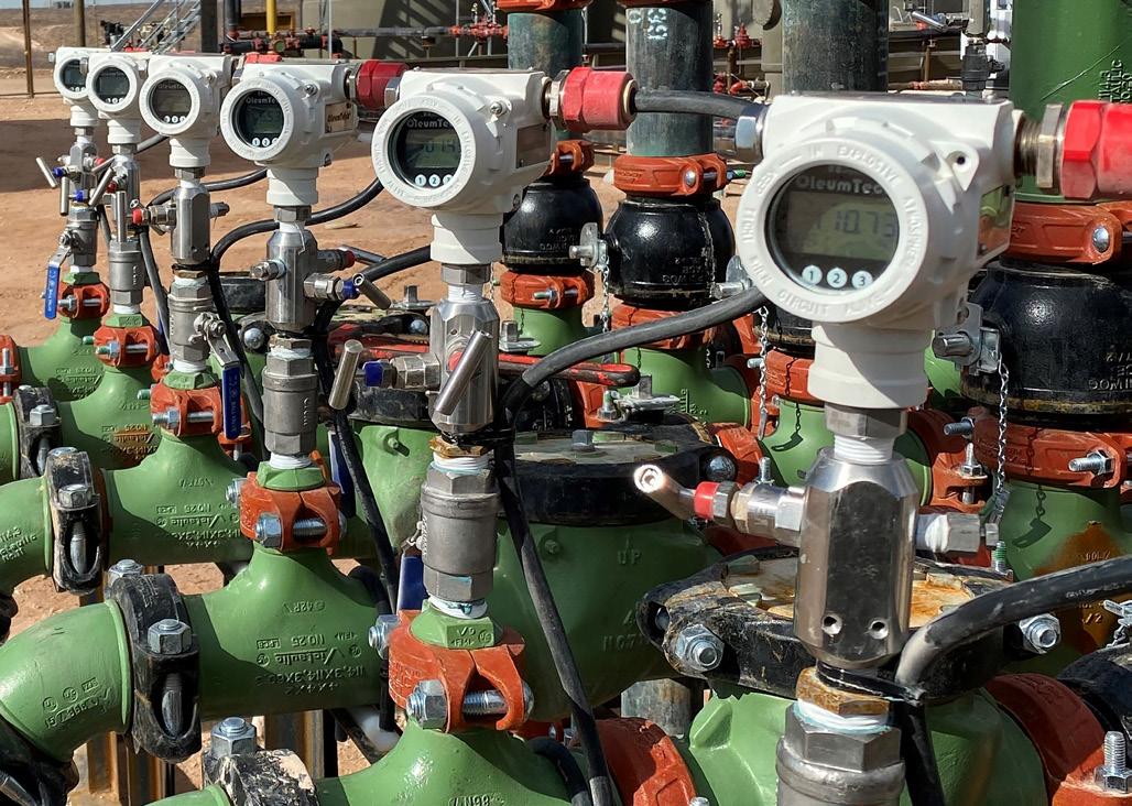
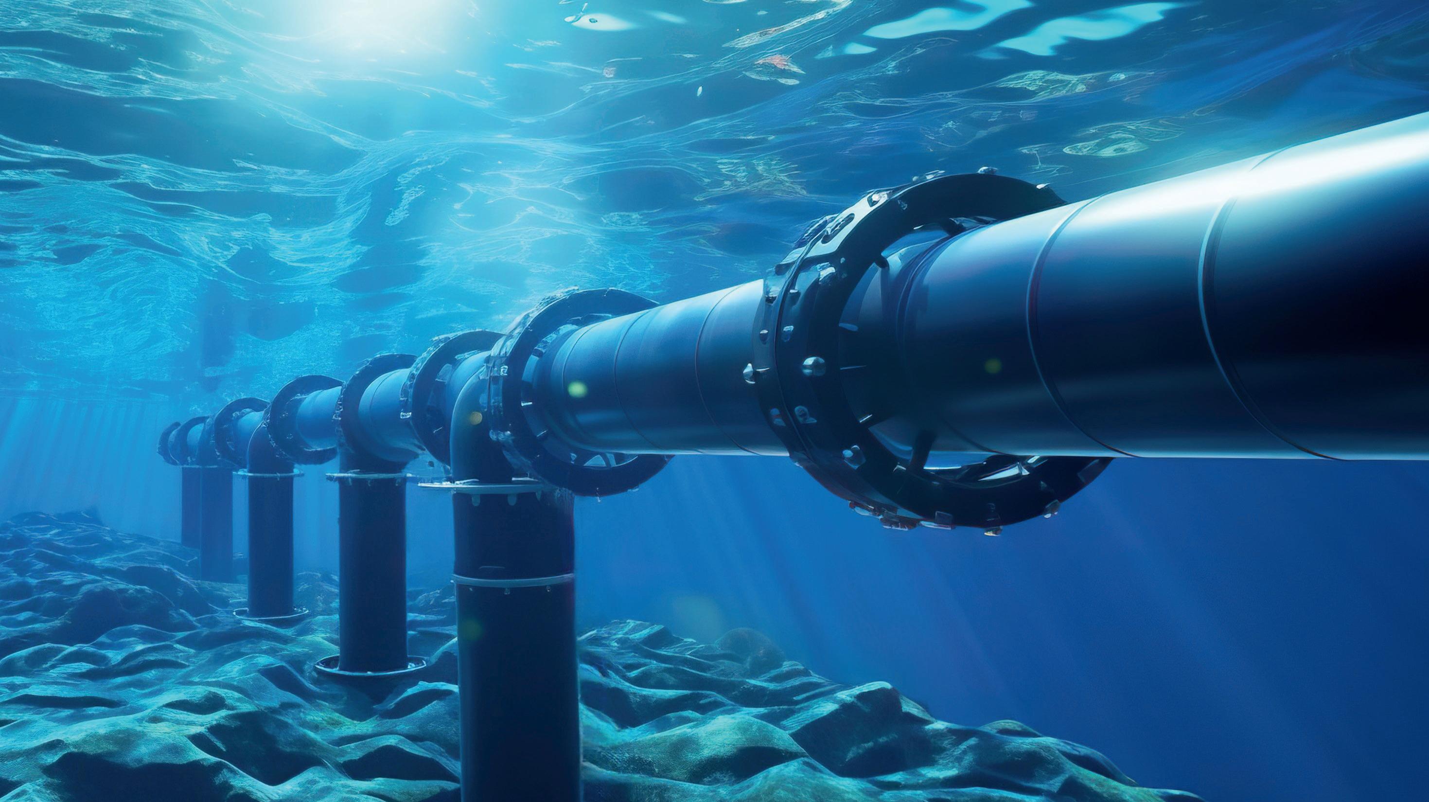
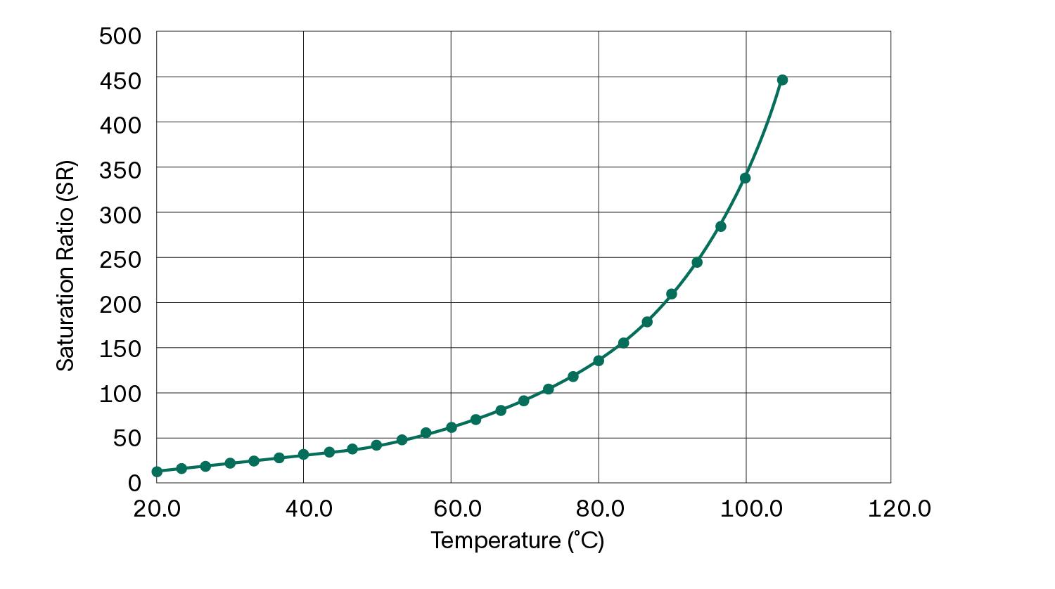
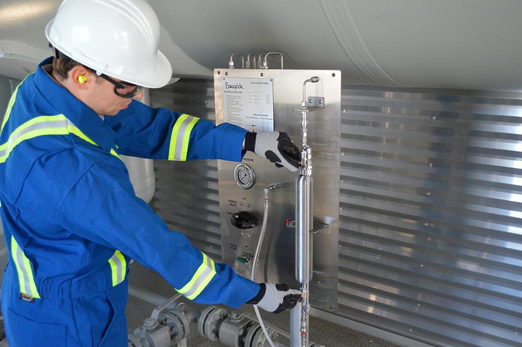
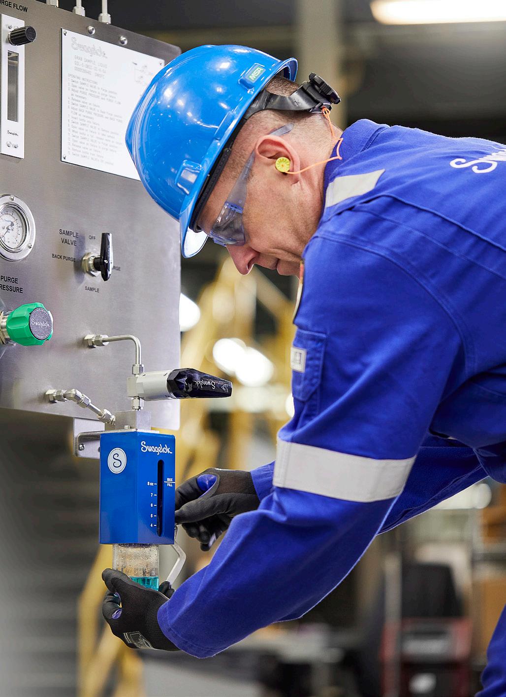
In the upstream market, automation is a standard practice for most producers. From an exploration standpoint, it has facilitated automated drilling operations, where rigs are equipped with sensors and real-time data analytics to accurately control drilling parameters, including depth, pressure, and torque. On the production side, automation applications focus on process control, safety, regulatory compliance, and production optimisation. This is achieved by utilising sensors for various measurement variables such as pressure (Figure 1), flow, temperature, and level.
Midstream and downstream applications
In midstream operations, automation optimises and streamlines the transportation, distribution, and storage of oil and natural gas. Pipeline monitoring systems equipped with sensors provide detection of leaks, corrosion, and/or pressure anomalies in real time, enabling corrective action to prevent environmental incidents or operational disruptions. In the downstream refining and petrochemical market, automated control systems manage complex processes ensuring consistent, on-spec product quality. Robotic systems are also being increasingly used for routine maintenance tasks, such as inspecting storage tanks or cleaning equipment, improving safety by reducing human exposure to these high-risk environments.
Benefits of automation
Automation brings several important benefits to the oil and gas industry. First, it improves operational efficiency by reducing downtime and optimising resource utilisation. For instance, predictive maintenance systems use sensor data to predict equipment failures, allowing for timely repairs that help avoid costly shutdowns. Second, automation enhances safety by minimising human exposure to hazardous environments, where explosive liquids, vapours, and gases can be present. Third, it lowers operational costs by streamlining processes and decreasing reliance on manual labour. Finally, automation promotes environmental sustainability by increasing process efficiency, reducing emissions, and facilitating better monitoring of environmental impacts.
Digitalisation: the data-driven revolution
Digitalisation refers to the integration of digital technologies into business processes, which improves automation by utilising data to inform decision-making. The oil and gas industry produces a substantial amount of data from sensors, equipment, and operations. Technologies such as big data analytics, artificial intelligence (AI), and the Industrial Internet of Things (IIoT) convert this data into actionable insights.
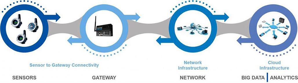
Big data and analytics
Big data and analytics have always been the most exciting piece of the IoT ecosystem (Figure 2) and are vital components, particularly in the oil and gas industry. They allow companies to process and analyse large datasets to optimise their operations. Advanced algorithms use real-time data from wells to enhance production by optimising flow rates and detecting anomalies, which helps maximise output while minimising costs and waste. Additionally, predictive analytics provides valuable insights into the performance of individual assets, enabling accurate forecasts of how operational initiatives will impact revenue and market demands.
Cloud computing and digital platforms
Cloud computing provides the necessary infrastructure for storing, processing, and analysing the vast amounts of data generated throughout the value chain, transforming it into actionable insights. Cloud-based platforms facilitate seamless collaboration among teams and assets spread across different geographical locations, allowing engineers, geologists, and data scientists to access and analyse data in real time. Additionally, these digital platforms leverage advanced technologies such as AI and IoT to utilise data and analytics effectively, driving
Microbiologically influenced corrosion (MIC) poses a significant threat to the integrity of oil and gas operations, primarily driven by biofilm formation and hydrogen sulphide (H2S) generation. These microbial processes accelerate corrosion, promote fouling, and disrupt flow assurance, resulting in increased maintenance costs and operational downtime. Controlling MIC typically involves a combination of mechanical cleaning and targeted chemical treatments.
Biocides are a critical component of MIC mitigation strategies; however, their effectiveness depends on their ability to penetrate the biofilm matrix and reach the microbial cells. Mature biofilms consist of complex mixtures of waxes, sediments, minerals, and extracellular polymeric substances that impede biocide access. Consequently, combining mechanical cleaning with biocide application is strongly recommended to ensure optimal microbial control.
Vink Chemicals offers advanced oil- soluble biocide solutions engineered to effectively integrate and disrupt biofilms, inhibit H2S production, and effectively mitigate MIC risks in oil & gas systems.
• Broad-spectrum biocides to target SRB, APB and other biofilm-forming microorganisms
• Synergistic biocide formulations to enhance biofilm penetration and disruption
• Oil-soluble biocide formulations for superior dispersion within crude oil, ensuring effective activity against microorganisms present in water droplets dispersed throughout the oil phase
• Environmentally compliant solutions meeting industry regulations while ensuring high efficacy
E-mail: oilgas@vink-chemicals.com www.vink-chemicals.com PRESERVED TO
innovation, enhancing efficiency, and contributing to a more sustainable energy future.
Industrial internet of things
The Industrial Internet of Things (IIoT) connects devices, sensors, and systems to form a networked ecosystem, allowing for realtime monitoring and control. In the oil and gas sector, IoT-enabled sensors placed on pipelines, rigs, wellheads, production tanks, etc. gather data on temperature, pressure, level, and flow rates. This data is then transmitted to centralised platforms for analysis. Such connectivity facilitates remote monitoring and control, reducing the need for on-site personnel and enhancing response times to operational issues. While connectivity is becoming more ubiquitous from cell networks, low orbiting satellites, and even private radio networks, many production sites are located in remote areas. To address this challenge, edge computing is employed to significantly reduce latency, allowing for real-time monitoring, control, and decision-making in critical operations.
Artificial intelligence and machine learning
AI and machine learning (ML) offer powerful benefits to the oil and gas industry, and new possibilities are constantly emerging with the current level of innovation. AI encompasses technologies that mimic cognitive functions associated with human intelligence such as reasoning, problem-solving, and decisionmaking. ML, a subset of AI, focuses on algorithms that improve performance through experience without explicit programming.1 These technologies power applications like predictive analytics. By processing vast datasets and uncovering patterns, AI and ML empower producers to make informed decisions and adapt to evolving challenges. Digital twins (Figure 3), powered by AI, connect the real and virtual world by collecting real-time data from installed sensors. The data is then simulated in the virtual instance to optimise performance of the real asset in a risk-free digital environment.
Benefits of digitalisation
Digitalisation provides transformative benefits for the oil and gas industry. First, it enhances decision-making by offering real-time insights into operations, which allows for quicker and more informed responses to challenges. Second, it improves efficiency by optimising processes and minimising waste, resulting in significant cost savings. Third, digitalisation promotes sustainability by enabling better monitoring of emissions and resource usage, helping companies meet environmental regulations. For example, ExxonMobil utilises digitalisation in its upstream operations to support its broader sustainability objectives, including the use of a Digital Reality Ecosystem (DRE), part of ExxonMobil’s version of an Industrial Metaverse2 which aids in strategic planning to reduce unnecessary interventions and associated emissions. At Industrial IMMERSIVE 2025, ExxonMobil’s Kyle Daughtry and Athicha ‘M’ Dhanormchitphong explained how the Digital Reality Ecosystem (DRE) program is helping ExxonMobil create a unified, data-driven view of its operations.3
Lastly, it enables companies to connect their assets and operations on a global scale, converging both operational and financial information. This level of convergence allows for complete integration across a company’s operation to build a ‘connected enterprise’. According to EY Digital Oil,4 the connected enterprise is the final phase and ultimate goal of digital adoption.
It is achieved when a company connects all of its assets and processes across an integrated value chain.
Challenges of automation and digitalisation
While automation and digitalisation provide significant advantages for the oil and gas industry, there are several challenges to consider. First, implementing these technologies requires a substantial upfront capital investment, which can be a barrier, particularly for smaller companies. Upgrading legacy infrastructure with modern systems often not only demands significant funding, but it may take years for the return on investment to become evident. Second, cybersecurity poses a major concern, as digital systems are susceptible to cyberattacks that could disrupt operations or compromise sensitive data. Third, the industry faces a skills gap; the transition to automated and digital systems necessitates a workforce skilled in data science, artificial intelligence, and cybersecurity. Lastly, regulatory and compliance challenges can hinder adoption, as companies must navigate complex environmental and safety regulations when implementing new technologies.
The future of automation and digitalisation
The future of automation and digitalisation in the oil and gas industry looks promising, with emerging technologies set to further transform the sector. Autonomous drilling systems, AI-powered controls, and robotics are expected to become more prevalent, enabling fully automated exploration and production processes. Additionally, blockchain technology is anticipated to further enhance supply chain transparency, ensuring secure and traceable transactions while eliminating the delays associated with current methods. Furthermore, advancements in quantum computing may unlock new possibilities for the industry. As these technologies mature and become more accessible, they are expected to play a vital role in optimising operations, improving sustainability, and driving innovation across the sector.
Conclusion
Automation and digitalisation are transforming the oil and gas industry by enhancing efficiency, safety, and sustainability throughout the entire value chain. Technologies such as automated drilling rigs, IoT-enabled pipelines, AI-powered analytics, and cloud-based platforms are enabling companies to address the challenges of a rapidly changing energy landscape and deliver value, regardless of market condition uncertainty. While there are obstacles like high costs, cybersecurity risks, and skills gaps, the advantages of automation and digitalisation – such as cost savings, improved decision-making, and environmental sustainability – far outweigh these challenges. As the industry continues to innovate, the integration of emerging technologies will further accelerate this transformation, allowing oil and gas companies to succeed by recognising the impact of their operational decisions on both current and future financial performance.
2. Siemens, The Industrial Metaverse. https://www.siemens.com/global/en/ company/digital-transformation/industrial-metaverse.html August, 2025.
3. Innovateenergynow.com, How ExxonMobil is Building its Digital Reality Ecosystem (DRE) https://innovateenergynow.com/resources/how-exxonmobilis-building-its-digital-reality-ecosystem-dre
4. EY Digital Oil, ‘Accelerating the oil and gas industry’s journey to the Industrial Internet’, ey.com/digitaloil, 2017.
insights
Gary Hickin and Jessica Stump, NOV, discuss how AI-powered insights can enhance real-time decision-making
and drilling performance.
odern drilling operations are more complex and data-intensive than ever. Extended-reach wells, high-pressure/high-temperature environments, and tighter drilling tolerances demand greater precision and speed. Simultaneously, expectations for safety, efficiency, and cost control continue to rise. Yet technical complexity is only part of the challenge for today’s drilling teams.
The ongoing big crew change is reshaping the workforce, as experienced personnel retire or leave the industry, creating critical knowledge gaps on drilling rigs worldwide. Meanwhile, the massive volume of data generated from sensors, surface systems, and downhole tools can overwhelm humans. Engineers spend considerable time managing this data deluge, increasing cognitive load and the risk of delayed recognition and response to issues such as washouts, pack-offs, and pressure anomalies.
Artificial intelligence (AI) is transforming drilling operations by enhancing situational awareness, improving decision-making, reducing risk, and codifying operational experience into scalable systems. These advanced tools excel at processing and interpreting real-time data, analysing trends, and detecting downhole dysfunctions early.
NOV’s Drilling Beliefs and Analytics (DBA) employs AI to provide realtime, actionable insights into critical well conditions. Using probabilistic models trained on real-time and contextual data, the system detects drilling and tripping dysfunctions early, enabling rig crews to respond before issues escalate and helping to mitigate risk and improve performance.
How it works
DBA combines edge computing, Bayesian Belief Networks (BBN), physics-based modeling, and decision tree algorithms to support real-time decision-making and predictive analytics. A BBN is a probabilistic model that understands variables and their relationships and calculates uncertainties to assess the likelihood of specific downhole conditions. DBA analyses all available data using Bayesian models and
decision trees to generate a belief – or probability index – that a particular event is imminent and requires attention.
While these AI-driven methods are complex, their outputs are intuitive and straightforward. Each belief is displayed on a custom dashboard as a value between 0 (not happening) and 1 (happening). Since the outputs of beliefs will fluctuate and trend, users set limits and alerts when the value exceeds or falls below a threshold.
To enhance situational awareness, DBA now incorporates graphical overlays that present quick views of potential issues, trends, and advisory notes on rig floor displays and office screens. These overlays are mirrored across the cloud-based viewer, ensuring consistent visibility to rig crews, office-based engineers, and remote operations centres (ROC). This approach improves traditional strip charts by adding contextual visual cues that help users interpret emerging conditions more quickly.
By monitoring a single channel that consolidates all relevant data, users can identify early warning signs and take informed action with confidence. In this way, DBA functions as a digital tap on the shoulder, alerting engineers when operating conditions shift toward defined risk thresholds. Just as modern vehicles alert drivers to tire pressure, low fuel, or other important advisories,
DBA delivers timely, actionable insights that help users get ahead of potential issues and reduce operational costs and downtime.
The system provides more than 40 beliefs in four core categories: drilling efficiency, hole cleaning, wellbore stability, and directional effectiveness. Supporting these beliefs are fully automated Torque and Drag, and Swab and Surge models. These models eliminate the need for manual data input and dynamically update as the system ingests real-time drilling and contextual data. With these simulations, rig crews can identify tight spots, set safe tripping speeds, and evaluate the impact of parameter changes on well conditions.
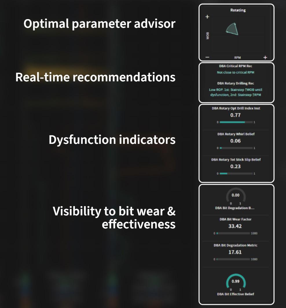
DBA also features a novel real-time drilling advisory concept, Cone Drilling. This widget reacts instantly to live data and uses the beliefs and models to summarise current rotary and sliding performance.
The Cone Drilling Gauge enhances performance and efficiency by providing qualitative recommendations for drilling parameters. Rather than delivering exact values, it suggests increasing or decreasing specific parameters, allowing drillers to adjust based on known thresholds or operational limits. This is one of the many ways to visualise data in DBA to optimise situational awareness.
DBA reduces manual workload by automatically pulling data directly from operational reporting systems. This streamlined process ensures outputs, including beliefs, models, and other engineering calculations, are continuously updated as conditions change, improving consistency and minimising the need for manual recalculations.
AI-driven insights at the edge
The DBA system follows an edge-first approach, using NOV’s rugged Max Edge technology to process and analyse data at the rig. This workflow ensures all critical insights are available to rig personnel on screens and human-machine interfaces, regardless of cloud connectivity.
All outputs from the system are also synchronised in real time to the cloud or an on-premises location using NOV’s high-speed data transmission protocol, reducing data latency to 2 - 3 seconds.
As an integrated application on NOV’s Max Platform™, DBA supports drilling efficiency by providing a single version of the truth and facilitating seamless collaboration from the rig to the office to ROCs. This application is accessible using
Figure 2. The latest iteration of DBA includes overlays that show key metrics and advisory information.
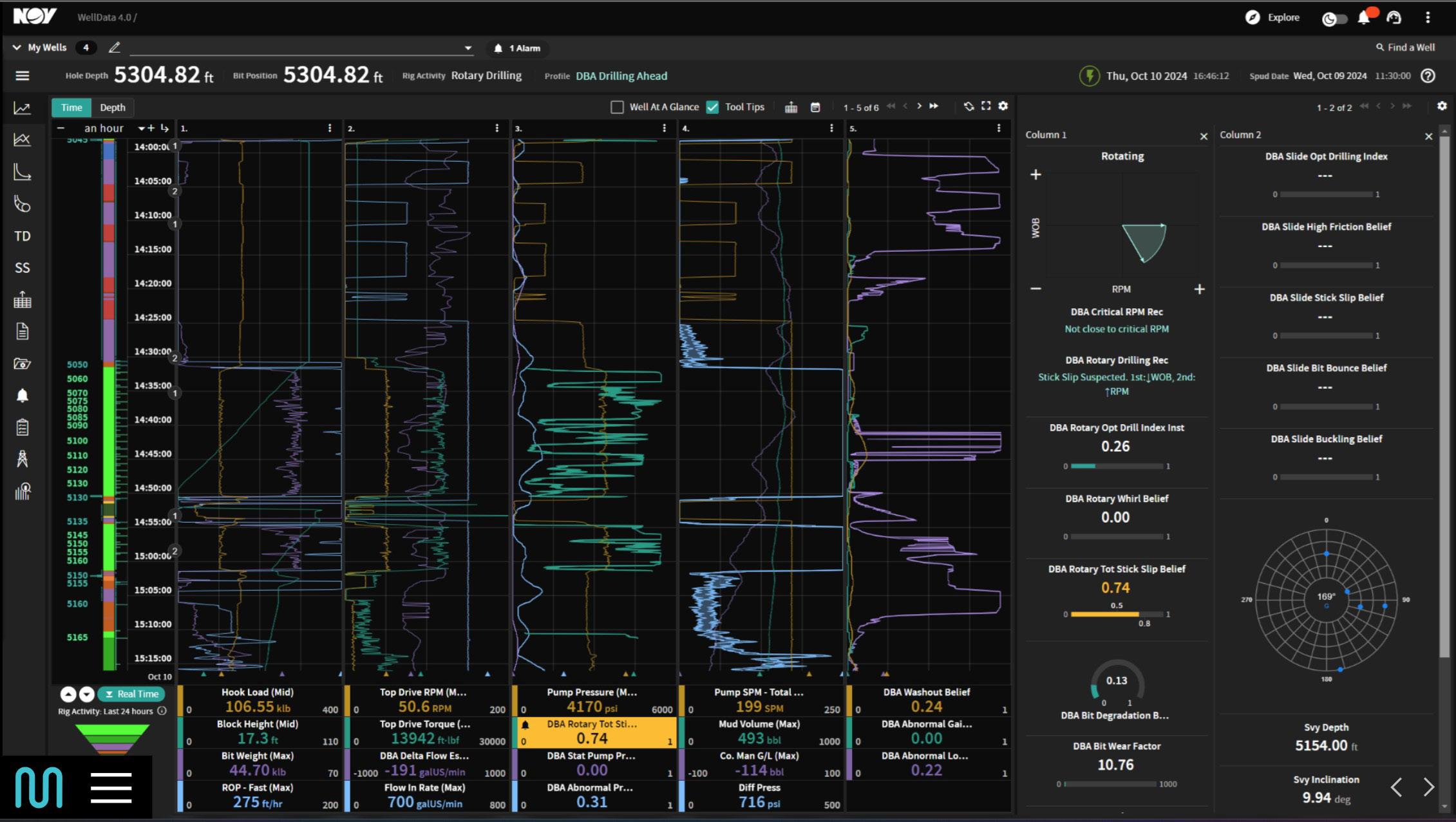
Figure 1. An example of a customised view of the Drilling Beliefs and Analytics dashboard.
the company’s unified data and visualisation solutions, RigSense in the field and WellData 4.0 in the cloud.
Abnormal pressure loss detection
Early detection of washouts in the drill pipe or bottomhole assembly (BHA) is crucial for drilling, as it helps prevent twist-offs that can result in unplanned downtime and costly fishing operations. A washout is a structural failure, such as a hole or erosion, in the drillstring that compromises fluid circulation.
Abnormal pressure loss during drilling typically indicates a failure in the fluid circulation system. Potential causes include a washout in the drill pipe (either in the body or at a connection), a BHA component or connection failure, downhole tool malfunction, surface mud pump issue, or fluid losses into the formation.
NOV’s DBA calculates an Abnormal Pressure Loss Belief by comparing real-time standpipe pressure (SPP) to a statistically modeled pressure curve calibrated using historical data from the same well. This belief model uses inputs including SPP, weight on bit (WOB), rotary speed (RPM), and flow-in rate.
When WOB, RPM, and flow-in are relatively stable, the belief tracks deviations in SPP trends. If the belief value exceeds a defined threshold, DBA flags a potential abnormal pressure loss event. The system then performs further analysis using contextual data, such as survey information and BHA configuration, to help identify the likely root cause.
Case studies
While drilling the 6.75 in. lateral section of a well in the Delaware Basin, a major operator received an Abnormal Pressure Loss Belief (0.56) that exceeded the alarm threshold. This trigger was followed by a gradual decline in SPP over one stand. After an initial surface pressure test returned inconclusive results, drilling resumed. Subsequently, a second, more pronounced SPP drop occurred. DBA flagged this event with higher confidence (0.71). Acting on these insights, the Drilling Systems Manager (DSM) decided to pull out of the hole (POOH) to investigate a potential washout.
While tripping out, rigsite personnel inspected the drillstring and identified a washout at the pin and box ends between two joints of drill pipe, which was confirmed by visible mud leakage at the surface. The accurate alert and timely response enabled the team to address the issue before it escalated.
Although the pressure trend was visible in the data, the DBA alert prompted earlier action, heightening attention and situational awareness. The integration of real-time analytics and field expertise enabled the team to avoid a costly twist-off, eliminate potential fishing operations or a sidetrack, and preserve well integrity and drilling efficiency.
On another Delaware Basin well, the same operator was drilling a 9.875 in. intermediate section when DBA simultaneously flagged an Abnormal Pressure Loss Belief (0.58) and a Washout Belief (0.47) above the alarm threshold. This occurred in tandem with a steady pump pressure decline. Compounding the challenge, erratic torque and RPM fluctuations were observed – clear indicators of high stick-slip vibration throughout the stand. Given these concurrent anomalies, the DSM decided to POOH to inspect for washout.
During the trip out, rigsite personnel conducted a visual and physical inspection of the drillstring. A washout was identified at the connection point between two joints of drill pipe. Following confirmation, the team reamed back to the bottom and resumed drilling.
Stick-slip dysfunction and gradual pump pressure decline may have delayed detection if not for the advanced alerting from
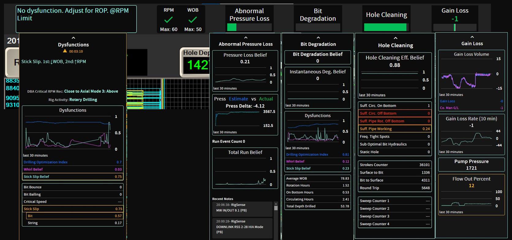
Figure 3. The DBA system gauges are displayed at the rig and in the office to highlight the current situation in real time.
DBA. The integration of analytics with field expertise led to early identification and response, preventing a twist-off. As in the previous case, the team avoided potential fishing operations, minimised downtime, and preserved well integrity.
Conclusion
DBA’s Abnormal Pressure Loss Belief enables operators to detect washouts earlier than traditional methods, often up to an hour before conventional surface parameters detect an issue. This capability is saving operators between US$750 000 and US$1.5 million in fishing operation costs related to twist offs.
Beyond lowering operational costs, DBA exemplifies AI’s transformational impact on drilling operations. Early detection of potential well control, hole cleaning, and wellbore stability issues enables rig personnel to act confidently, reducing non-productive time, mitigating equipment loss, and improving well delivery.
Importantly, AI is not about replacing humans. While job roles will evolve, AI empowers people to work more efficiently, collaborate more effectively, and make smarter, faster decisions. It also helps preserve and scale operational knowledge. By capturing insights and patterns recognised by experienced personnel and embedding them into probabilistic models and automated workflows, AI-driven solutions like DBA help bridge the knowledge gap between legacy expertise and emerging talent. This codification transforms tacit knowledge into structured logic, ensuring that best practices are consistently applied across crews, fleets, and projects.
By focusing on enhancing human capabilities – problem solving, collaboration, and innovation – and developing more intelligent, adaptive systems, NOV is advancing the digital transformation of the energy industry. Through edge-based, AI-driven applications like DBA, NOV is not only enabling safer and more efficient operations but also helping to build a smarter, more resilient workforce.
Reference
1. Cortez, J., Elghor, M., Peroyea, T. et al. 2025. Preventing Drill String Twist Off: Automatic Flagging of Abnormal Pressure Loss Signatures in Real-Time. Presented at the SPE Conference at Oman Petroleum & Energy Show, Muscat, Oman, 12–14 May. https://doi.org/10.2118/224876-MS.
Danny Constantinis, EM&I, Malta, addresses methods of maintaining the integrity of Floating Production Units (FPUs) and Floating Production, Storage, and Offloading (FPSO) assets.
roviders of asset integrity management (AIM) are often asked what is different about floating production units (FPU) and their hull integrity, when compared with trading ships? The straight answer of course, is that FPUs cannot physically or cost-effectively go to drydock for inspection, repair, and maintenance (IRM); particularly for the complex end of the IRM scale; on-station alternatives must be found. The quest for these solutions requires disruptive innovation, collaboration, agreement, and endorsement from owners, operators, regulators, including, particularly, the Classification societies (Class).
Collaboration through forums such as the Hull Inspection Techniques and Strategy Joint Industry Project (HITS JIP) passing its tenth anniversary this year, have developed diverless IRM techniques for FPUs. To demonstrate this success, this article will use sea valves on floating production, storage and offloading
(FPSO) assets as an example of collaboration, research and development (R&D), and highly skilled technicians to apply the techniques.
Sea valves: do they matter?
The FPSO comprises three main parts: the topsides, the hull, and marine systems, and each part plays an important role in how the vessel operates and handles its tasks. The passage of water through the hull is essential to the installation’s operations: sea water inward; and produced water outward. Regular inspections and maintenance are necessary but can be expensive and timeconsuming, as offshore repairs are difficult to carry out.
FPSO hull penetration sea valves are critical for controlling the flow of sea water in and out of the vessel, which is essential for processes such as cooling, equipment operation, and sea water injection.
Ì Cooling: FPSOs require significant amounts of sea water for cooling equipment and various processes; sea valves control the flow of sea water for cooling systems, ensuring efficient operation of the vessel’s machinery.
Ì Sea water injection: sometimes used to inject into oil wells to enhance production; sea valves are part of the system that manages sea water for this purpose, allowing for controlled injection into the wells.
Ì Overboard dumping: discharge of sea water overboard may be required for various reasons, such as cleaning or ballast water management; sea valves are part of the system for controlling the discharge of sea water.
Ì Process control: sea valves are also used to isolate and control various sea water-related systems, ensuring the safe and efficient operation of the FPSO.
Ì Sea water treatment: sea water may need to be treated to remove impurities like sulfates and air; sea valves are part of the system that manages the treatment and distribution of treated sea water.
Most sea water is drawn into the installation through sea chests.
Therefore, sea valves are critical to the safe and effective operation of a floating production installation:
Ì Safety and reliability: critical for ensuring the safe and reliable operation of the FPSO, protecting equipment, and maintaining product quality.
Ì Efficiency: contributing to the overall efficiency of the FPSO by ensuring smooth and controlled operations.
Ì Environmental protection: proper valve function helps ensure that wastewater and other byproducts are treated and discharged into the sea in accordance with regulations.
Ì Downtime reduction: reliable sea valves minimise the risk of production interruptions, which can be costly.
As most intake of sea water and overboard discharges are below the water line, the sea valves control passage of water through penetrations in the wetted hull; their failure to open and close reliably and fully is a significant risk to hull integrity, operations, and Class or other regulatory compliance.
Sea valves are therefore integral to the entire FPSO and all FPU systems.
Implication of sea valve failure?
Failure of the sea valves to function as designed will have a critical impact on the safe and effective operation of the installation. While there are likely to be back up mechanisms and built in
Figure 4. Integrity Class ROV.
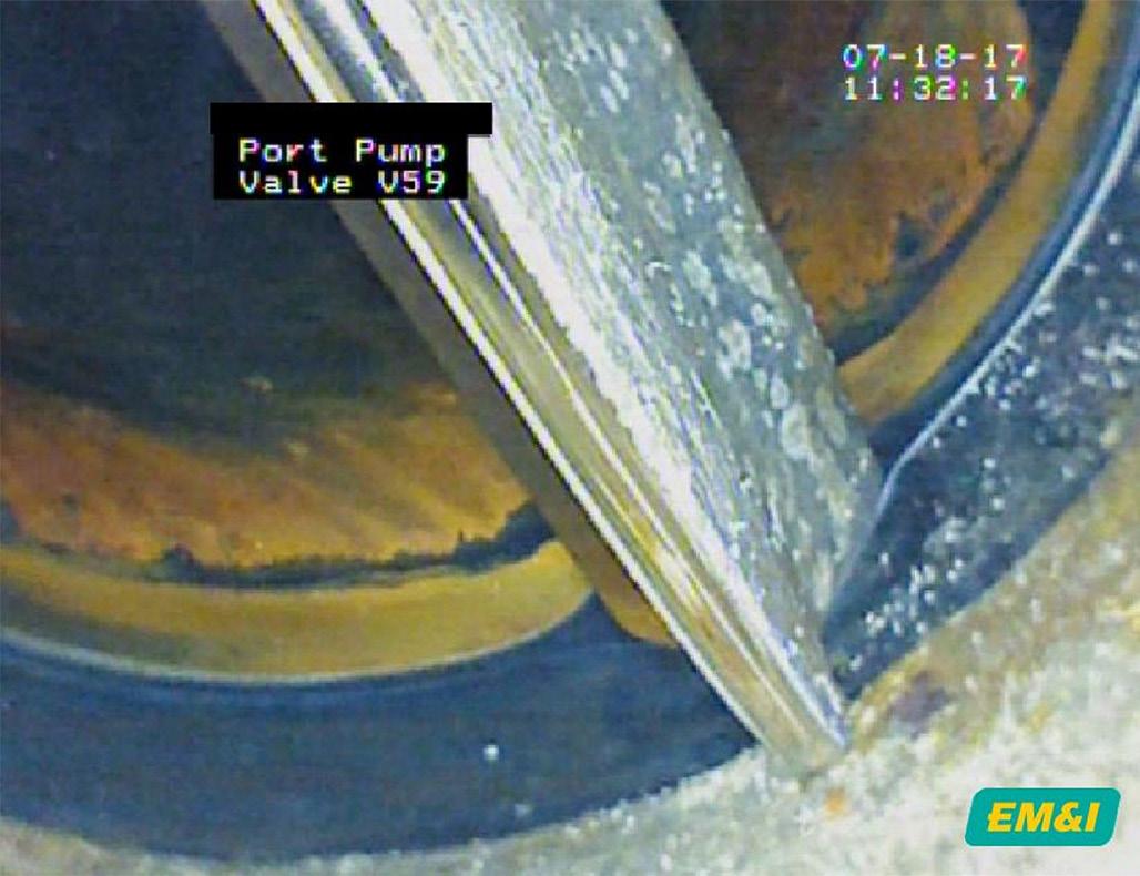
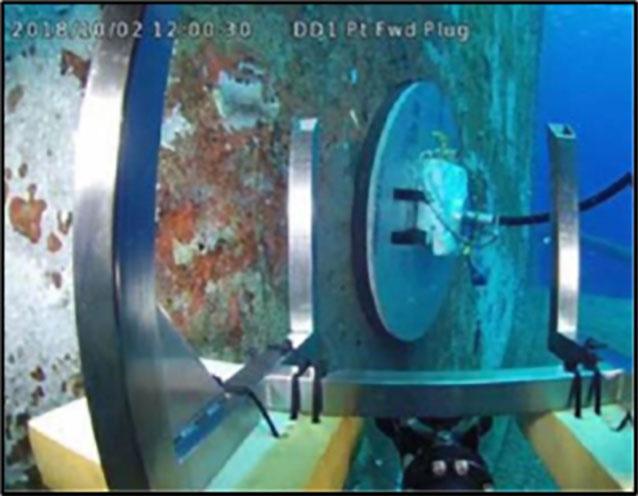
Figure 3. System in operation – high resolution camera inserted through an ODIN Port.
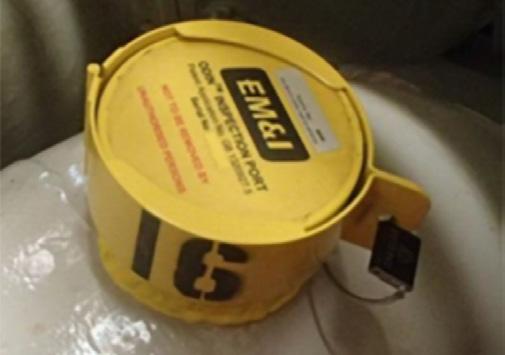
Figure 2. ODIN® Access Ports.
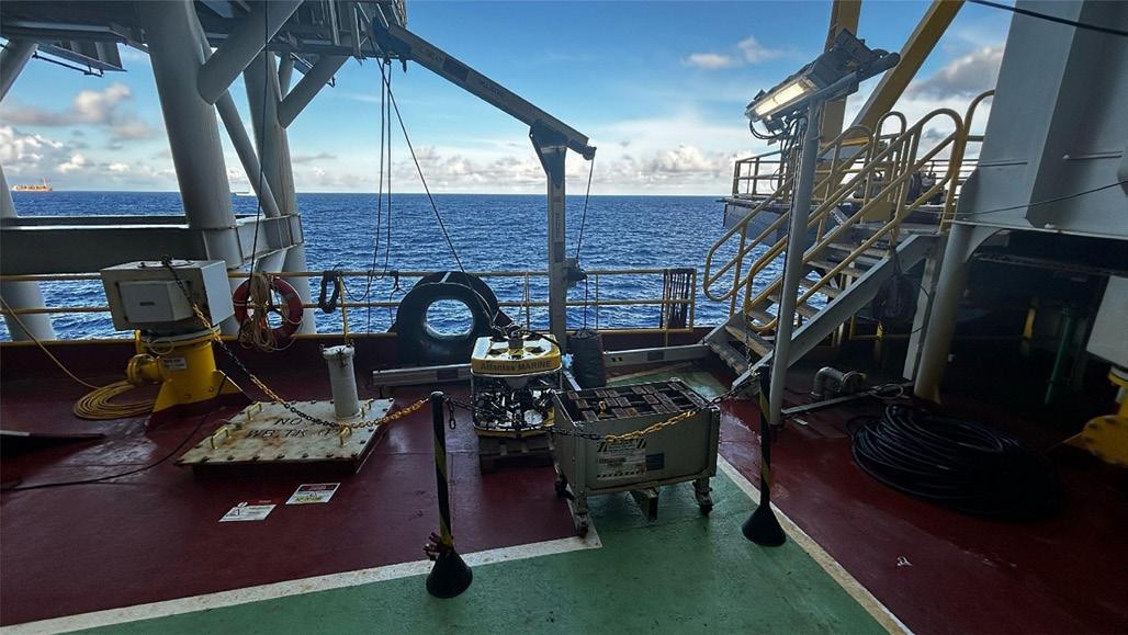
Figure 1. EM&I’s Integrity-Class ROV on board an FPSO.
redundancy, implementation reduces effectiveness and will have a significant safety and commercial impact on routine operations.
If they fail in the open position, and subsequent piping also fails to contain the flow, there is a risk of the installation filling with water, at high volume, and given the size of some of the sea lines – at high velocity – therefore potentially overwhelming the systems. Given the central position of the valves in the overall system, this failure is likely to occur in critical areas such as engine rooms and machinery spaces. If failing ‘closed’, the systems will not be able to function safely, or at all.
So, who would really care about any such failure?
Clearly anyone with more than a passing interest in the effective operation of the asset, and particularly those with significant economic, financial, reputational, and safety responsibilities; owners, operators, regulatory bodies including Class, Flag State, and the national governments which would have to bear the impact of any subsequent environmental impact; the stakes are high.
Diverless IRM
Understanding the challenges facing the industry, EM&I has developed the ODIN® suite of diverless inspection, maintenance, and complex repair capabilities, including:
Ì Remotely operated vehicles (ROV)-based, including underwater inspection in lieu of drydocking (UWILDs), complex hull inspection and repairs – reducing reliance on inherently high-risk diver operations.
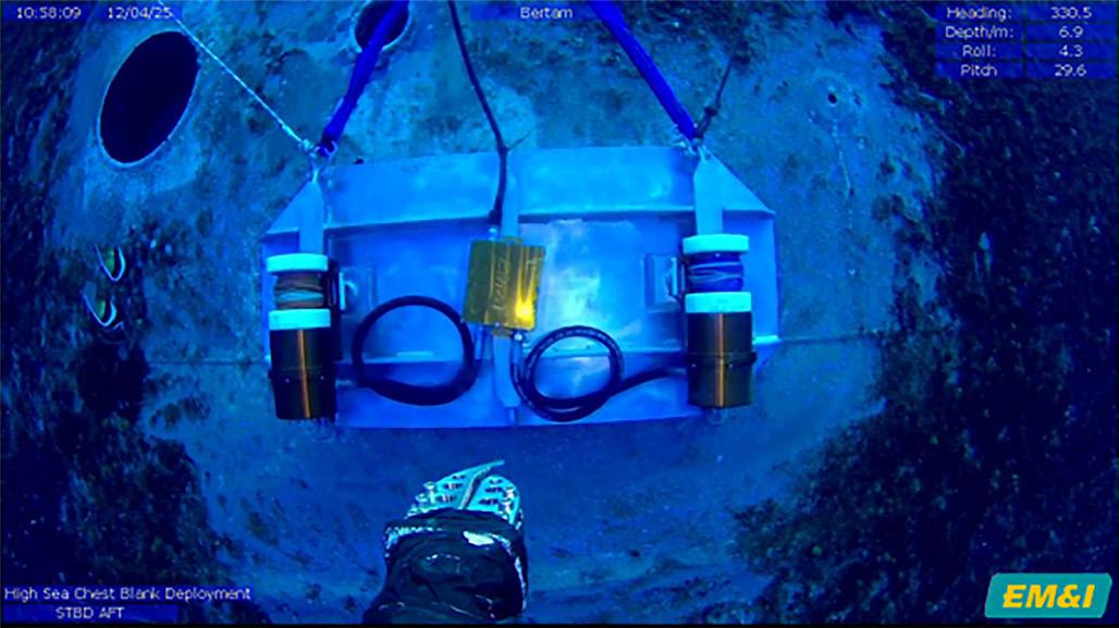
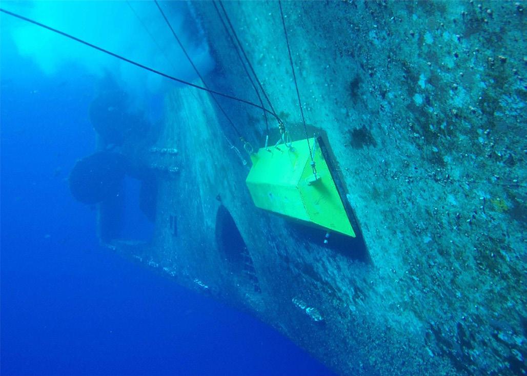
Ì LIMPET®: sea chest blanking for skin valve isolation for repair and replacement, and sea chest inspection.
Ì PLUG®: overboard discharge plugging for skin valve isolation.
Ì CLAM®: remote application of bespoke coffer dams for complex hulls steel repair and replacement.
Worldwide Coverage
Given the location of these valves, how do we know their condition, certainly before the failure of the system? They are generally inaccessible, in sealed piping systems, inboard of sea chests, or in the case of overboard discharge lines, some distance from the hull penetration.
Class have recognised this and give wavers providing that in-water surveys or UWILDs, can demonstrate meeting of the regulatory requirements. A key part of the periodic surveys mandated globally by Class, is the visual inspection of sea valves to assure integrity of the hull; how can this be achieved?
After testing various means of assessing sea valve integrity using divers, ROVs, borescopes, and the like, the conclusion was that none of the above methods provided sufficient information on sea valve and seal fitness for service. This led to the development of a process and equipment to provide the quality of information needed to assure integrity between surveys.
The first step was to assign criticality levels to each valve so that an appropriate level of inspection could be programmed.
Second, to design a tool that gave the needed quality of inspection and functional testing to support Class periodic inspections and owners’ needs for maintaining critical valves.
Following direction and support from the members of the HITS JIP, EM&I developed the ODIN sea valve/sea chest inspection tool.
The inspection tool access ports are fitted to the sea lines (during construction or hot tapped during operations) through which high-definition robotic cameras are inserted. This enables clear visibility of the valve, the face, the seal, function, effectiveness, state of repair, leak rate, and thus assessment of current integrity as well as any damage, and assessed life expectancy. The access port itself is designed to ensure hull integrity at all times – double block with a Class-approved valve
– and mitigating the risk of corrosion on the cut edges of the sea line with a sacrificial anode, and a ‘top hat’ to adhere and protect coatings of the sea line.
High criticality valves can be inspected through the access ports, while lower criticality examples inspected by traditional non-destructive testing (NDT), and function test; this is a quick and low-cost alignment, using the same multiskilled team, but ensuring all valves are covered.
Historically, divers watched from outside the hull to try and see the valve functioning, but clarity and detail have always been a challenge, let alone the inherent risk to human life. ROVs can replace the diver, with high capability cameras, but still, providing sufficient detail of valve faces and seals has been challenging.
Market feedback
When anomalies on client assets are identified, remote inspection achievements are built on, developing techniques for complex isolation, repair, and renewal without the use of divers, negating the requirement for drydock, and thus saving clients significant cost.
Given the design life of modern installations, it is proving to be highly likely that sea valves and sea chests will require maintenance and repair, or replacement at some stage during that period.
In collaboration with owners and operators through the HITS JIP, and in one-to-one engagements, these solutions have been developed to maintain the ‘no diver’ continuum. This avoids the requirement for dry dock thus saving cost, and enables the replacement of valves while maintaining normal operations.
Diverless solutions
The development of LIMPET is for the remote blanking of sea chests, and PLUG is for the application of a double block to overboard discharge lines. Both capabilities enable the isolation of sea valves for more detailed inspection, or removal for repair or replacement.
The LIMPET capability consists of a bespoke design sea chest blank, which is lowered from the installation’s deck, guided by vision through an ROV, and physically assisted if required, secured to the sea chest inlet by intelligent winches, which can be attached even if there is no coaming on the inlet design. The seal is assured, and the sea chest is then drained to enable a dry working environment for the isolation work to be carried out. Once complete, the process is reversed.
In contrast, PLUG involves the insertion of an inflatable bladder into the overboard discharge line, with a secondary blocking plate to act as the double block when the bladder is inflated. Constantly monitored for pressure, the seal remains in place while the work on the valve is conducted.
The final element of the trio is CLAM – the deployment of a cofferdam to cover the area of the hull requiring steelwork to be completed. The structure is winched into place using ODIN access ports fitted in the hull around the work area to complement the hydrostatic pressure. Once the seal is assured, the cofferdam is drained, and steel repairs, cutting, replacement, and recoating can be completed safely, securely. All of this can be completed while the asset is operating, and without the need to go into dry dock.
Conclusion
In conclusion, sea valves – for both sea water suction, and overboard discharge – are critical to the integrity of hulls and floatation elements of FPUs, including renewable energy assets, such as for floating offshore wind. We have collaborated with clients, heard their feedback, and have expanded the capabilities from underwater inspection, now to include secure, effective, and reliable maintenance and repair techniques. EM&I has developed and proven a complete system for the management of sea valve and sea chest integrity, approved by Class to ensure broader compliance with their regulatory framework and rules. Many clients have the vision to see the opportunity presented by technology to mitigate safety risk and still ensure that diverless IRM is the safest and most cost-effective way to assure sea valve and sea chest integrity.
Figure 7. CLAM® Cofferdam.
Figure 6. PLUG® deployed in FPSO Overboard Discharge Lines.
Figure 5. LIMPET® deployed on an FPSO Offshore Malaysia.
A customisable approach
Nasraldin Alarbi, Senior Product Champion – Cementing, and Afshin Ahmady, Technical Advisor – Cementing, Halliburton, discuss how customised design approach reduces the risk of uncertainty in lost circulation control.
Lost circulation is a major cause of nonproductive time (NPT) in oil well construction and poses financial and health, safety, and environmental (HSE) risks. In extreme cases, it could lead to total well loss and abandonment. Such outcomes are rare due to advances in treatment technologies and increased industry experience.
Other consequences may include:
Ì Loss of large volumes of drilling fluid to the formation.
Ì Hole instability and poor wellbore cleaning while drilling or cementing.
Ì Increased risk of stuck pipe, downhole tool loss, and fishing operations.
Ì Sidetracks if fishing operations are unsuccessful.
Ì Annular plugging and early cement job termination.
Ì Failure to achieve the planned top of cement (TOC).
Ì Compromised zonal isolation and costly remedial work.
Ì Safety or environmental incidents caused by well control situations.
These outcomes can result in NPT, unplanned contingency operations, and increased well costs.
Repeated lost circulation material (LCM) treatments increase expenses, which makes it essential to design effective solutions from the start. Effective treatments start with a clear grasp of the lost circulation problem.
High-permeability formations require particulate-type solutions to reduce permeability at the formation face. In contrast, fractured formations may warrant larger bridging materials or chemically reactive solutions, such as thixotropic cement. This type of cement creates a high-gel-strength barrier to seal thief zones. Even within the same loss mechanisms, such as fractured formations, it is important to understand the formation characteristics to help optimise the treatment and improve the chances of success.
For this reason, Halliburton developed a science-based and methodical approach that uses geological analysis, material science, and fluid mechanics to customise bridging LCM packages. This approach accounts for pore throat size, porosity, estimated fracture size, local LCM material properties, and the density and rheological profile of the carrying fluid. The goal is to design a mixture of multiple
bridging materials with complementary physical properties that plug the formation and cure the lost circulation event.
From uncertainty to accuracy: advanced modelling for effective lost circulation treatment
While legacy regions may have established treatments, there is room to improve their effectiveness and reduce costs. As drilling extends deeper, into older and depleted reservoirs where lost circulation is more prevalent, operators often lack sufficient experience to manage the losses. In addition, new exploration areas lack proven treatment methods. In these scenarios, a science-based and methodical approach is essential. It outperforms outdated legacy tables and lost circulation decision trees, minimises trial and error, and reduces NPT.
When Halliburton treats lost circulation events with bridging materials, three key design criteria are applied:
Ì Select an LCM concentration that plugs the fracture.
Ì Determine the maximum pumpable concentration that avoids plugging downhole restrictions.
Ì Choose fluid properties that best transport the LCM package.
These considerations are crucial when cementing, where the risk of plugging downhole tools is greater than while drilling.
The approach involves two key steps. First, engineers run a computer simulation that uses digital twin models. The primary model predicts the required LCM materials and concentrations to plug the target geometry. The algorithm considers wellbore hydraulics, loss zone dynamics, and filter cake modelling. It uses a hydraulics engine model that simulates downhole conditions and fluid dynamics to predict slurry behaviour under various temperatures and pressures in actual cement operations. The model also estimates loss zone geometry through a hydraulic match that applies pre-job circulation data, well geometry, loss type, rate, and location. This defines key loss zone characteristics, which are then used to predict loss rates, volumes, and pressures as different fluid trains pass through the loss zone throughout the cement job. With the integration of downhole hydraulics and loss zone dynamics, the model estimates the loss conduit geometry (if unknown) and identifies the optimal LCM blend and fluid properties to plug the fracture.
The second model evaluates the maximum safe concentration of the proposed LCM package that can pass through downhole restrictions, such as float
Figure 2. Computer modelling assesses the LCM package and concentration for its ability to pass through a given geometry and the carrying fluid’s capacity to transport it.
Figure 1. Computer modelling evaluates the LCM package and concentration for the ability to seal a given geometry.
equipment or liner hanger clearances. The model evaluates particle safe passage, transport efficiency, and static suspendability.
Cement specialists use both software models throughout the job design and customisation phase to balance the most effective LCM/fluids package with one that will clear critical downhole dimensions.
After the LCM package is designed with digital twin models, it is then tested in the lab with a plugging apparatus to confirm its effectiveness to seal the target geometry.
Accelerate design of service
This science-based and methodical approach facilitates the development of customised LCM packages tailored to specific issues that utilise local available materials. These include organic or biodegradable materials for environmentally sensitive locations, acid-soluble packages to reduce the risk of formation damage, and thermally stable formulations for geothermal and high-pressure, hightemperature (HPHT) applications. In ultra-high temperature applications, this design approach helps control lost circulation and improve cement mechanical properties, such as tensile strength and elasticity. This dual-function capability is valuable in unstable, depleted, or fractured formations where formation creep is a concern.
Cement specialists can also tailor the LCM specific gravity with precision to match a wide range of fluid densities – from low-density spacers to high-density cement systems. This approach helps ensure compatibility and supports proper placement within a broad range of well conditions without settlement or flotation under static conditions.
This approach also allows designs that incorporate local materials to help ensure a quick turnaround and reduce supply chain delays. In the event of a material shortage, materials are replaced with alternatives without a compromise to performance. This accelerates the design of service and reduces NPT.
In addition, this approach serves as a valuable risk assessment tool. It predicts the concentration limits of LCM through specific tool dimensions to help prevent service quality incidents, such as pressure-out events, while cementing. This reduces the risk of premature cement job termination, remedial work, and NPT.
Success in the field: total losses cured in vuggy, karstified dolomite formation
Introduced in 2022, this science-based and methodical approach to lost circulation has delivered impressive results in hundreds of global applications and cured lost circulation during both drilling and cementing. A recent success in the Middle East exemplifies the benefit of this approach.
The Dammam formation in southern Iraq is a karstified dolomite that presents a unique set of lost circulation challenges. Up to 90% of wells in the area experience significant total lost circulation attributed to geological characteristics, such as caverns, vugs, and large fractures. Operators and service companies have exhausted options to address losses in this formation with conventional LCMs and thixotropic cement systems. Conventional solutions required an average of five cement plug treatments
supplemented with LCMs, and several days to drill through the section.
Halliburton executed a customised design approach to tailor a lost circulation treatment that consisted of a blend of fibres, resilient angular particles, and coarse materials. The package was designed with digital twin models that considered geological formation characteristics, and physical lab tests verified the solution. In the field, the LCM package was batch mixed into the cement slurry and placed down an open-ended drill pipe. The losses were treated with a single plug compared to the usual three to six plugs required in previous wells. This saved the operator an average of 34 h of rig time and allowed them to drill to total depth, run casing, and complete the primary cement job with minimal losses. This design approach is now the operator’s preferred method to cure losses in the area.
Customised approach improves lost circulation in well construction
Lost circulation throughout well construction can diminish drilling efficiency, increase costs, and could potentially affect HSE performance. Identification of the loss source is key to the appropriate treatment selection. When bridging materials are required, a science-based and methodical approach to lost circulation package design is crucial.
This approach helps improve treatment success rates and reduces operational risks, costs, and environmental impact. It transforms uncertainty into precision through advanced modelling, real-time data utilisation, and tailored material selection to deliver reliable solutions even in difficult geological formations. The approach gives operators confidence in Halliburton’s ability to deliver effective, field-proven solutions for lost circulation. As drilling advances into deeper and more complex formations, this method sets the standard for efficient operations that maximise customer asset value.
Figure 3. Physical lab tests confirm the LCM package and concentration’s ability to seal the expected geometry.
Gary Choquette
Elizabeth Corner
EPISODE NINE
A conversation about the research, collaboration, and science behind safer, cleaner, and more efficient pipeline operations. Featuring Gary Choquette, Executive Director of Research at the Pipeline Research Council International (PRCI).
Gary shares his thoughts on:
• What PRCI does, and how it decides what to focus on.
• The Technology Development Centre in Houston – and why it’s a game changer.
• The industry’s readiness for hydrogen, CO2 and future fuels.
• Why collaborative research beats solo efforts every time.
• How PRCI supports transparency, safety and trust in the public eye
LISTEN NOW
CATCH UP ON RECENT EPISODES
Episode Eight: AMPP
Episode Seven: UKOPA
Episode Six: TDW
Risk mitigation: Scaling back challenges
Kim Vikshåland, ChampionX, explains how the risks were mitigated through the identification and optimisation of appropriate chemical treatments for scale inhibition via topside, subsea and squeeze applications.
ince 2016, production from Vår Energi’s Goliat field in the Barents Sea has been impacted by a variety of inorganic scale management challenges. In this article Kim Vikshåland, Senior Account Manager for ChampionX, 1 recently acquired by SLB, explains how the risks were mitigated through the identification and optimisation of appropriate chemical treatments for scale inhibition via topside, subsea, and squeeze applications.
Located in the Barents Sea, around 85 km northwest of Hammerfest, the Goliat field, with water depths ranging from 320 m to 420 m, is the first oil-producing field in the northernmost area of the Norwegian continental shelf. Prior to and following field start-up in 2016, ChampionX had worked closely with Vår Energi to develop and supply chemical technologies that have supported the long-standing success of the field,
adapting to address the needs of the wells as they evolved over time.
Since first oil, barium sulfate formation, resulting from the injection of sea water (Figure 1) for reservoir pressure
Figure 3. Co-production of high-calcium Kobbe formation water, together with high-bicarbonate Realgrunnen formation water, led to an extremely high saturation ratio (SR»250) for calcium carbonate at the topside heaters.
maintenance, and calcium carbonate formation, caused by temperature and pressure changes throughout the production process, have been the predominant scale management challenges for the field.
Scale management at Goliat is further complicated by the requirement for production chemicals to perform and remain stable in a challenging arctic environment, and with low reservoir temperatures of 32 - 50˚C.
The field produces from two main reservoirs, Realgrunnen and Kobbe, with 16 subsea wells tied back to a zero-discharge floating production, storage, and offloading (FPSO) unit for processing.
Oil is stored before export by tanker, while the produced gas and water are reinjected for pressure support in dedicated wells. Additional pressure support is provided by the injection of seawater, without sulfate removal, into injection wells. Some wells received seawater injection initially, when produced water rates were not high enough to provide sufficient pressure support, but now receive only produced water, while some wells remain supported by seawater only.
The risk of barium sulfate scaling comes from injecting sea water into already barium-rich formation water. ChampionX carried out simulation studies, which confirmed the potential for severe downhole barium sulfate deposition, leading to agreement that chemical scale inhibitor squeeze treatments would be necessary to mitigate this risk (Figure 2).
A calcium carbonate scaling risk was identified from the need to apply heat to the well fluids to aid separation, due to the relatively low fluid arrival temperatures at Goliat.
Identifying a scale management strategy
Having defined the predominant scaling mechanisms and areas of production at risk, ChampionX’s next step was developing a scale management strategy to mitigate against scale deposition, refining it prior to, and during, production. The three key components of the strategy were:
Ì Continuous scale inhibitor injection to reduce deposition of calcium carbonate scale in topside heaters.
Ì Regular acid washes to maintain the efficiency of the topside heaters.
In addition to these measures, each dependent upon the application of chemical products to the system, the injection of produced water and seawater for reservoir pressure maintenance was also used to partially mitigate the downhole barium sulfate threat.
4. Since the first treatment, Well C4 has been squeezed a further 10 times with ongoing optimisation of treatment volumes based on the field data received.
Scale squeeze treatment at Goliat
Qualifying a scale inhibitor for squeeze application was an extended process, which included input from both ChampionX and Vår Energi. Coreflood experiments evaluated the potential for chemical-induced formation damage.
Precisely determining the residual scale inhibitor concentration in the produced fluids, in combination with ion
Figure 1. Goliat FPSO, Image shared courtesy of Vår Energi.
Figure 2. Barium sulfate scaling simulation studies confirmed potential for severe downhole deposition.
Figure
A podcast series for professionals in the downstream refining, petrochemical, and gas processing industries
LISTEN NOW
Sponsored by
EPISODE 12
Omar Sayeed, Centre of Excellence Leader for Reliability, and Rahul Negi, Director of AI and Industrial Autonomous, Honeywell Process Solutions, consider how new, innovative technology can help to overcome some of the challenges facing the downstream oil and gas sector.
EPISODE 13
Sarah Miller, President and CEO of the GPA Midstream Association and CEO of the GPSA, outlines the vital importance of midstream operations, and some of the key challenges and opportunities facing the sector.
EPISODE 14
Rob Benedict, Vice President, Petrochemicals and Midstream, American Fuel & Petrochemical Manufacturers (AFPM), discusses the outcomes of the final round of UN negotiations for a Global Plastics Treaty.
EPISODE 15
David Wilson, CEO, Energy Exemplar, considers the role that oil and gas is currently playing in the booming data centre industry, and what the future holds.
analysis and well productivity index, was also essential to determine the lifetime efficiency of the treatments.
At Goliat, this presented a significant challenge due to mixed brine composition in the flowline and the requirements to analyse multiple families of scale squeeze inhibitors in the same sample, without interference from the continuously injected wellhead or topside scale inhibitors and any other production chemicals.
Optimising squeeze treatments at Goliat
The approach to scale inhibitor squeeze deployment and monitoring at Goliat was developed through collaboration between ChampionX and Vår Energi, employing a combination of conventional analysis of scale inhibitor residuals and modelling based on experimental results to predict the lifetimes of squeeze treatments. Here, a single squeeze inhibitor, A, was deployed in all wells at risk of barium sulfate deposition following seawater breakthrough.
This approach proved successful following seawater ingress (the point at which the scale risk began) into well C4. In this case, analysis of the residual scale inhibitor concentration within the produced water allowed for the design and optimisation of subsequent squeeze treatment.
Since the first treatment on well C4, it has been squeezed a further 10 times with additional optimisation of treatment volumes being applied based on the field data received (Figure 4).
With the new design, the main treatment was increased by 112%, and the overflush by 197%. However, with this new treatment programme, well C4 is protected for a produced water volume of 145 700 m3. This is a 536% increase, equal to 100 additional days of squeeze treatment life, based on current production rates. The ongoing optimisation has enabled the squeeze volumes to reduce per water volume treated.
When further wells required protection via scale squeeze treatments, Inhibitor A was also successfully applied.
Carbonate scaling in topside process
In addition to the challenges associated with downhole barium sulfate scaling, conditions within the topside heaters resulted in high potential for calcium carbonate scaling at Goliat.
During the pre-production phase, a polymeric scale inhibitor was qualified for use. Following the commencement of oil production in March 2016, continuous application of this inhibitor to the topside process was initiated.
By April 2018, water breakthrough had begun and the Goliat operations team had begun to identify carbonate scaling issues in the topside heaters. Initially, the injection rate of the polymeric scale inhibitor was increased to compensate and scale dissolver treatments were applied to the heaters.
It became clear that co-production of high-calcium Kobbe formation water, together with high-bicarbonate Realgrunnen formation water, led to an extremely high saturation ratio (SR»250) for calcium carbonate in the topside heaters. This led to a re-evaluation of the topside scale management strategy and an alternative topside continuous injection scale inhibitor was selected (Figure 3).
In response to the presence of calcite in the inlet heaters, a new phosphonate scale inhibitor was applied, initially trialled in March 2019 and implemented permanently from March 2020.
Concurrently with the implementation of the new phosphonate chemistry, a project was initiated to develop a novel scale inhibitor for the Goliat topside system, based on a synergistic formulation of scale inhibitors. Prior experience with severe scale regimes had illustrated the benefits of using complementary combinations of scale inhibitors, where the treatment rate required to achieve control with the formulated product is significantly lower than the treatment rate required for either of the individual components.
Screening of several inhibitors was performed to determine whether synergistic effects could be identified to cope with the high carbonate scaling potential present in the Goliat inlet heaters. Following exhaustive trialling and testing, a new synergistic formulation, Inhibitor B, was put forward for field evaluation.
Based on the results, Inhibitor B for Goliat topside scale control has become a permanent application and continued field optimisation has been undertaken, resulting in a reduction in chemical usage.
Scale dissolver treatments
The potential for calcium carbonate formation at Goliat is exacerbated by the process conditions within the topside heaters. The primary method of mitigating this risk would usually be the continuous application of a scale inhibitor upstream of the heaters. However, operational experience at Goliat has demonstrated that the very high scaling potential in this system leads to a gradual accumulation of calcium carbonate scale in the heaters that requires periodic removal by application of scale dissolver.
A common approach to the problem of removing mineral deposits from topside heaters is to take the heater offline and apply a batch treatment with acid (mineral or organic) to dissolve any scale present. However, the approach employed at Goliat involves ‘online’ application of organic acid while fluids are still flowing through the heater. To facilitate this, the well configuration between the two subsea flowlines is adjusted such that a low water rate is produced via the heater to be cleaned. This allows a higher concentration of acid to be achieved in the heater whilst it remains online.
Conclusion
Through a collaborative and adaptive approach, ChampionX and Vår Energi have successfully navigated the complex scale management challenges that have evolved over their 10-year partnership on the Goliat field. By identifying the distinct risks posed by barium sulfate and calcium carbonate scaling, and implementing tailored chemical treatment strategies across downhole, subsea, and topside systems, the teams have significantly extended treatment lifetimes and improved operational efficiency. Innovations such as the deployment of a new synergistic scale inhibitor formulation and online acid treatments have further enhanced performance, reducing chemical usage and downtime. These efforts underscore the importance of continuous optimisation and partnership in maintaining production integrity in harsh offshore environments.
Reference
1. At the time of publishing, SLB, a global energy technology company, has closed its acquisition of ChampionX, a global leader in production chemistry solutions, artificial lift systems and advanced technologies. The contents of this article represent a customer project performed by ChampionX prior to closing.
COVER STORY
Matthew Snape and Jennifer Knopf, Vink Chemicals, and Matt Streets, Rawwater, discuss long term preservative biocides for biogenic souring control.
he study in this article presents the outcomes of an extended pressurised bioreactor investigation evaluating the long-term souring control efficacy of Vink Chemicals’ biocide, grotan® OX, against a mixed oilfield microbial consortium.
Reservoir souring, driven by microbial activity, particularly sulfatereducing prokaryotes (SRP) and other anaerobes, poses a persistent challenge in oilfield operations. The evolution of biogenic hydrogen sulfide (H2S) not only contributes to asset corrosion and health, safety,
and environment (HS&E) hazards but also affects crude quality and processing economics. Traditional short-term kill prevention strategies often fail under long-residence-time conditions prevalent in deep injection systems. There is a growing need for long-acting, broadspectrum biocides capable of metabolic suppression over months, not just hours.
Case studies have been reported where a conventional biocide was applied over several months in a high salinity, low flow offshore waterflood system. Initial H2S levels decreased after dosing but increased again within a few days, indicating a resurgence of microbes. This suggested that conventional biocide chemistries were unable to provide any remedial capacity and therefore could not persist long enough to cause any significant prevention through metabolic suppression. This is not an isolated example.
These experiences underscore the need for next-generation biocide strategies, those that go beyond microbial kill and instead aim for long-term metabolic inhibition, biofilm disruption, or even quorum sensing interference.
This article presents a rigorous comparative study of grotan OX, Vink Chemicals’ high-stability oxazolidine biocide, under simulated field conditions over 17 weeks.
Materials and methods
Bioreactor setup
12 water-saturated bioreactors were constructed and operated at the Rawwater UK laboratories. The columns operated in parallel under pressurised, anoxic conditions at 1000 psig and 30°C to simulate common downhole near wellbore environments. All bioreactors were packed with a pre-established sand matrix, populated with a mature, diverse, sessile oilfield microbial community.
During each weekly batch injection cycle, a baseline injection water consisting of anoxic synthetic seawater supplemented with
120 mg/L mixed VFAs (at a ratio of 100:10:10 of acetate, propionate, and butyrate respectively) was injected as a carbon source typically available in an oil-bearing reservoir to support microbial activity at an injection flow rate of 5.0 mL/min.
Two biological replicates were run for each of the following treatments:
Ì Industry incumbent – glutaraldehyde (A1/A2).
Ì Industry incumbent – THPS (B1/B2).
Ì In-house candidate – confidential (C1/C2).
Ì grotan OX (D1/D2).
Ì Controls (PC1/PC2).
Injection scenario and dosing strategy
During each of the first three injection cycles, one third of the measured swept volume was replaced in each bioreactor using the baseline injection water. In week 4, the entire swept volume of each bioreactor column was replaced in preparation for the week 5 biocide dosing campaign.
Biocides were dosed at concentrations reflecting typical field-use levels. All biocides were applied across the full swept volume of all treated bioreactors at 750 ppm/v product. Following biocide dosing in week 5, the bioreactors received a one-third swept volume injection between weeks 6 and 17, allowing for a real-time evaluation of biocide performance and long-term persistence.
Analytical methods
Weekly monitoring included:
Ì ATP/ADP/AMP measurement using luminescence assays leading to calculated values and ranking of AMPi/AEC which gauge metabolic load, activity/dormancy and inferred stress.
Ì MPN enumeration in PRD/MPB media to estimate general heterotrophic bacteria (GHB) and SRB planktonic culturable populations from the water of each bioreactor in six-fold serial dilution.
Ì H2S measurement by colorimetric, methylene blue sulfide assay to determine microbial sulfide generation over time (limit of quantification, LoQ, 0.5 mg/L).
Ì VFA content by ion chromatography (IC) to generate mass balance profiles for microbial VFA consumption using injection water VFA concentrations and produced water VFA concentrations (LoQ, 0.2 mg/L).
Molecular review: qPCR (targeting Total Prokaryotes, Sulfate Reducing Prokaryotes, Sulfur Oxidising Bacteria) and a suite of NGS and bioinformatic reviews performed at weeks 0 and 17 to understand sessile microbial community shift. All molecular sequencing analysis and reporting in this work were performed by LuminUltra Technologies Ltd.
Figure 1. High-pressure bioreactor set-up at Rawwater’s UK laboratories.
Figure 2. grotan® OX Mole Fraction vs. AEC: 3x timepoints: immediately before dosing (week 5), 1 week after dosing (week 6), and then 12 weeks after dosing (week 17).
Results and discussion
ATP-based metabolic activity (AEC/AMPi)
Ì Relatively stable AEC from the untreated PC1/2 bioreactors over the 17-weeks of operation showing an active population.
Ì Significant disruption in AEC across all biocide-treated bioreactors in week 6 from active growth to a degree of dying or dormancy following biocide dosing in week five.
Ì Relatively stable AMPi from the untreated PC1/2 bioreactors over the 17 weeks of operation showing limited to no microbial population stress.
Ì Significant disruption in AMPi across all biocide-treated bioreactors in week 6 from active growth to a degree of Lethal stress (following biocide dosing).
Ì grotan OX was the only biocide that provided sustained lethal stress in week 6 across both duplicate bioreactors.
Ì AEC and AMPi were utilised as metrics to understand microbial population recovery.
Ì grotan OX was the only product that provided AEC data points showcasing dying or dormancy until week 17, reaffirming its credentials for long lasting suppression and a hold on microbial recovery.
AEC charts as shown in Figure 2 show the red zone as no metabolic stress, while the green zone reflects transition where stress is inferred from biocide additions or environmental shifts. By week 17, a portion of stabilisation occurred, but the system did not return to the red zone, indicating persistent yet controlled metabolic stress conditions, this is often considered key to controlling a return to a biogenic souring threat window.
Serial dilution MPN enumeration (culture)
Ì A recovery in culturable mesophilic planktonic GHB and SRB numbers were observed following biocide chemistry ‘wash-out’ (weeks 10, 13, and 17).
H₂S evolution/VFA utilisation
Ì Significant sulfide concentrations were measured from all 10x bioreactors prior to biocide dosing (weeks 1 - 5).
Ì The calculated VFA consumption based on measured injection water and produced water VFA concentrations aligned with the measured sulfide generation throughout bioreactor operation.
Ì Relatively stable, significant sulfide concentrations were measured within the control bioreactors in the absence of biocide dosing.
Ì Significant souring recovery from bioreactor dosed with THPS was measured between weeks 9 and 17, peaking at 50.5 mg/L (week 17).
Ì Significant souring recovery from bioreactor dosed with in-house candidate was measured between weeks 9 and 17, peaking at 25.5 mg/L (week 17).
Ì Significant souring recovery from bioreactor dosed with glutaraldehyde was measured at week 17, peaking at 4.3 mg/L.
Ì A key observation was that no significant sulfide concentrations were measured from the duplicate bioreactor group dosed with grotan OX. grotan OX was the only biocide candidate that provided long term biogenic sulfide suppression, despite a portion of culturable cell recovery and changes in AMPi lethal stress markers.
Molecular insights – qPCR and NGS
It is commonly known that molecular data cannot differentiate between living and dead cells; therefore, the resulting datasets must be interpreted cautiously. They should be considered alongside microbial load assessments and stress parameters described in previous sections, ensuring that data interpretation reflects both viable activity and microbial load contributions to the overall microbial profile.
Initial review of the NGS dataset highlights the following trends:
Ì Hydrocarbon-degrading organisms (e.g., Alcanivorax, Marinobacter, Cycloclasticus) were among the most abundant groups across multiple samples, confirming strong selective pressure from residual hydrocarbon presence.
Ì Sulfate-reducing and sulfur-cycling organisms (Desulfotignum, Desulfofustis, Desulfuromusa, Dethiosulfatibacter) were prominent, particularly samples PC1 (control), A1 (Glutaraldehyde), and B1 (THPS), indicating significant risk for reservoir souring and sulfide-driven corrosion.
Ì Fermenters and acid producers (notably Fusibacter and Halanaerobium) were enriched in multiple samples, suggesting strong potential for acid generation and MIC acceleration.
When viewed alongside the NGS metabolic group distributions, qPCR enumeration helps contextualise which microbial guilds dominate the biomass. For instance:
Ì The PC1 (control) and B1 (THPS), the strong qPCR signals align with NGS results showing enrichment of sulfate reducers, hydrocarbon degraders, and fermenters, suggesting that the biomass quantified is functionally relevant to MIC and souring risk.
Ì The Inoculum basis qPCR confirms biomass presence, with NGS resolving it further into a hydrocarbon-degrader and sulfur-cycler dominated community.
We can summarise the microbial community structure differences as per Figure 5.
The inoculum establishes a worst-case scenario, showing how diverse microbial groups expand under nutrient-rich, uncontrolled conditions. Its dominance by fermenters, sulfidogens, and hydrocarbon degraders reflects an environment primed for rapid biofilm development and reservoir souring if left unmanaged.
Figure 3. grotan® OX vs control – tracking of ATP, AMP ADP and the use of AEC and AMPi calculations and assessment of biocidal performance and control.
Figure 4. Control (no biocide treatment) vs grotan® OX with respect to H2S evolution/VFA utilisation.
The PC1 control demonstrates the consequences of hydrocarbon enrichment: microbial biomass expands exponentially, with hydrocarbon degraders (e.g. Marinobacter, Alcanivorax) driving secondary metabolisms. This fuels sulfur oxidisers, reducers, and sulfidogens, generating conditions for both severe souring and multipathway corrosion. The complexity and redundancy of PC1 highlight the resilience of these microbial consortia.
Glutaraldehyde (A1) partially reduces microbial loads but fails to eliminate key functional species. Hydrocarbon degraders persist at high levels, while fermenters and manganese oxidisers sustain corrosion potential. Souring is moderated compared to PC1, but redundancy ensures continued activity. This reflects an incomplete control strategy with significant MIC risks.
THPS (B1) exerts pressure on some groups but leaves behind a robust anaerobic, reservoir-type community enriched with SRB, fermenters, and methanogens. This configuration is especially problematic, as it reproduces reservoir-like souring niches. Thiosulfate
reducers and methanogens indicate ongoing sulfide and acid generation, presenting a dual corrosion–souring threat. grotan OX (D1) achieves stronger suppression of microbial activity relative to PC1 and B1. While hydrocarbon degraders and SRB persist, their populations are substantially reduced, with less dominance of fermenters and sulfidogens. The risk profile indicates controlled souring and moderated corrosion pathways, though localised biofilmdriven MIC remains possible. Overall, grotan OX supports better longterm control with reduced functional redundancy.
Conclusion
The extended bioreactor study under simulated field conditions demonstrates the remarkable long-term effectiveness of grotan OX for biogenic souring control. Compared to both established and inhouse candidate, grotan OX delivered:
Ì Superior metabolic suppression sustained for over 17 weeks and beyond.
Ì Substantial reduction in viable biogenic hydrogen sulfide formers.
Ì Minimal to no biogenic H2S recovery or evolution under the most severe simulated reservoir conditions.
Ì Profound community disruption, verified via qPCR and NGS.
These attributes highlight the strong potential of grotan OX as a reliable, long-acting preservative biocide solution for both remediation and prevention of biogenic souring in oilfield environments. Its performance advantages are particularly relevant in reservoir systems with long residence times, highpressure injection operations, or restricted accessibility where frequent chemical dosing is not feasible.
Recommendations
PC1 Control
A1 Glutaraldehyde
B1 THPS
Extremely high (>2.2 billion degraders)
High but reduced (approximately 943 million degraders)
Substantial (approximately 699 million degraders, 129 million SRB)
Marinobacter, Alcanivorax, Desulfotignum Severe souring and multipathway corrosion Hydrocarbonfuelled microbial hub
Fusibacter, Alteromonas
Desulfotignum, Methanolobus, Halanaerobium
Marinobacter, Alcanivorax, Desulfuromusa
Deposit-driven MIC, moderated souring
Reservoir-type souring, MIC, methanogenesis
Controlled souring and moderated corrosion
The promising laboratory findings will now be progressed into controlled field trials, particularly in seawater and produced water injection systems with documented souring challenges. These trials will assess both short-term efficacies, such as initial microbial kill, and longterm performance under operating conditions. Parallel monitoring of microbial activity, sulfide levels, and overall system integrity will be essential to ensure reliable laboratory-to-field translation. Once field validation proves successful, a scale-up and deployment strategy would be developed. This would involve creating system-specific application guidelines, integrating the solution into existing chemical treatment programmes, and ensuring alignment with operator health, safety, and environmental requirements.
Partial control, resilient species remain
High-risk, anaerobic hotspot
Stronger suppression, lower redundancy
Table 1. qPCR and NGS molecular sequencing summary
Figure 5. Next generation sequencing summary – microbial species distribution.
Eric Kvarda, Principal Applications Engineer, Swagelok, details how by eliminating unnecessary complexities, potential leak points, and excessive maintenance requirements, a standardised plan for sampling points can save oil and gas operations millions.
our ability to deliver consistent on-spec products while maintaining optimal uptime on assets relies on accurate process sampling and analysis. The grab sampling process (sometimes referred to as ‘spot sampling’ or simply ‘sampling’) is a tried-and-true method to verify process parameters in the oil and gas industry. It enables verification of online analyser results and provides a practical alternative to expensive analyser installations. But each sampling point represents a potential risk for operators. Unexpected process emissions can create environmental issues, jeopardise worker safety, and cause additional issues.
That is why sampling points represent a unique opportunity for oil and gas operators to shore up their emission control metrics, enhance product quality control,
and strengthen workplace environmental health and safety. Let’s explore the benefits of optimal, standardised sampling practices, and the equipment that makes them possible.
Mitigating leaks through proper assembly
Fluid system leaks and unintentional emissions throughout any oil and gas operation can be detrimental to efficient operations and can range in severity. For example, leaks known as fugitive emissions are uncontrolled emissions of gases from process equipment primarily due to unwanted leaks. Volatile organic compounds (VOCs), such as benzene, methane, and hydrogen
1. Reducing emissions involves keeping fluids and gases contained within an optimally designed sampling system. These types of systems draw in fluids and flow them through the sampling point where a portion of the sample is collected in a sealed container (a cylinder or bottle) before the system returns the fluid to the main system.
2.
sulfide, are the main gases of concern. VOCs can jeopardise air quality, contributing to the degradation of the ozone layer. As a result, government agencies are setting limits on fugitive emissions, and violating these regulations can lead to substantial fines.
Any such leaks occurring at sampling points throughout oil and gas installations should be swiftly rectified. Sampling point leaks not only cause environmental issues, but can jeopardise user safety, especially since technicians typically come into close contact with the system when drawing a sample. For example, hydrogen sulfide exposure, even in low concentrations, can result in significant health risks to operators. Further, leaking or otherwise malfunctioning components at sampling points can compromise sample representativeness. Leak-tight sampling systems help technicians avoid misdiagnosing nonexistent analyser issues.
So, we know that fluid leaks and fugitive emissions are an issue. But what causes them?
Improper fitting assembly
Errors in system assembly are one of the most common sources of leaks throughout oil and gas applications, regardless of the system media. The frequency of these errors is often proportional to the installer’s level of training and experience. For example, not all tube fittings look and feel the same during installation, which can contribute to user error. Inspecting connections after assembly will greatly reduce the frequency of leakage during commissioning or startup.
Suboptimal valve performance
Valves are an important part of sampling system operations, responsible for controlling the flow of media throughout the system. They’re also a common culprit for leaks. To mitigate such leaks in critical applications, designers should seek out certified low-emissions valves (including those that adhere to American Petroleum Institute [API] 624 and API 641 standards).
Improper operation of the grab sample panel
In many sampling system designs, valves and other components must be operated in a certain sequence to properly take the sample. If steps are not followed correctly, the operator risks taking a sample that is not fully representative of the fluid stream. Or worse, accidentally discharging samples into the atmosphere, which risks both emissions and the safety of the operator.
Inconsistent panel design across facilities
At many sites, panels that perform the same basic operation may vary in design or assembly, requiring operators to follow distinct sets of procedures for safe sampling. Inconsistent procedures can lead to confusion, increasing the risk of improper operation, leaks, or a compromised sample.
Improper panel design for the application
Sampling panels should be designed and constructed with the needs of the application in mind. For example, a panel designed for non-hazardous fluids should never be used for an application involving hazardous fluids. The panel may not have the proper design or safety features to prevent undesired venting of hazardous fluids to the atmosphere. Installing or removing the sample container is a critical time when process fluid venting often occurs.
Figure
Limiting the potential for human error at sampling points is one of the most effective ways to limit leaks.
Figure
The good news is that sampling panels are available that can inherently reduce these types of risks, helping to eliminate leaks, contribute to uncompromising sample accuracy, and enhance safety throughout the site.
The qualities of leak-tight sampling systems
Reducing emissions involves keeping fluids and gases contained within the system. Optimally designed sampling systems do exactly that. Such systems draw in fluids and flow them through the sampling point where a portion of the sample is collected in a sealed container (a cylinder or bottle) before the system returns the fluid to the main system. This is all achieved without exposing the operator or the atmosphere to the fluid at any point.
What makes this method preferable to others? Some sampling methods involve drawing process fluid, flowing it through the sample point, and flaring or otherwise disposing of the excess. Other methods may simply tap part of the main process while the operator manually draws fluid into an open container. These alternative methods not only increase the potential for unwanted emissions via flaring or exposed processes, but they can also present significant safety threats to operators.
Optimised systems often represent the best method to help operators reduce emissions and maintain safe working environments since they can eliminate waste by returning fluid to the main process, and they can shield both operators and the environment from exposure to the fluid.
There are a few features to look for when selecting ideal sampling panels:
High-performance components
A sampling system’s overall quality depends on the quality of its components. For example, low-emission (low-E) valves1 – tested to the API standards –can be incorporated into the design to help prevent leaks. Certified low-E valves and other components are becoming increasingly common throughout the industry, and in various fluid system applications, as emissions regulations become stricter.
Proper assembly and design that minimises potential leak points
Even the highest-quality valve or fitting has the potential to leak in certain circumstances, especially if proper installation practices are not followed. For this reason, sampling panels that have been designed with as few connection points as possible can limit the potential of leaks and unintended emissions. Regardless of design, it is important that grab sampling systems are assembled and tested by trained specialists to minimise the probability of issues.
Optimal sample drawing technology
Leaks can also occur at the point where the technician draws the sample into a bottle or cylinder container, but there are technologies that can help minimise this potential. In a liquid system where samples are collected in bottles, for example, the fluid is commonly dispensed via a needle that pierces a rubber septum. Ideally, as the needle is withdrawn, the rubber septum reforms a complete seal. Lancet point needles are commonly used in these applications, but they may accidentally cut or ‘core’ the septum, allowing fluid to escape. A better needle design option is the pencil point needle, which reduces the potential for cutting the septum. It has a unique
Figure 3. Standardising your facility’s grab sampling panels will help you maintain profitability, efficiency, and safety while making sure that your product is within customer specifications.
design that discharges the sample through a hole on the needle’s side.
User-friendly
operation
Limiting the potential for human error at sampling points is one of the most effective ways to limit leaks. Here are a few ways to minimise the opportunity for error by design:
Ì Mount detailed step-by-step instructions directly on the panel. These should be easy for operators to read and should be able to withstand the environment without dissolving or fading.
Ì Standardise sampling panel designs site-wide. Use as few distinct designs as possible so operators do not need to learn unnecessary or extra sampling procedures.
Ì Design for ease of operation. The panels themselves should be easy to operate. For example, a single control dial may be able to actuate multiple valves in the correct sequence, limiting the potential for human error. Additionally, handle positions should be clearly marked to indicate intended function.
Choosing prefabricated assemblies from a reliable supplier can help reduce the potential for poor installation practices or design inconsistency. Suppliers may also be able to provide training for your technicians, making sure they all have the proper knowledge for reliable panel operation.
Standardising sampling across your operations
Oil and gas professionals can consolidate panel suppliers to ensure that each distinct piping and instrumentation diagram (P&ID) results in the same panel layout. Identical P&IDs can result in wildly different panel component selection and layout due to variance in assembler interpretation, which may cause unnecessary confusion when taking the sample. This practice can also help simplify maintenance and component replacement when required, minimising variability on required spares. Ultimately, standardising your facility’s grab sampling panels provides reliable data to ensure process accuracy and that your product is within customer specifications. For oil and gas professionals everywhere, it’s worth your consideration – profitability, efficiency, and safety can all be positively impacted.
Navigating the complex reality of decommissioning Navigating the complex reality of decommissioning
Richard Vann, RVA Group, explores the region’s complex decommissioning demands and highlights the critical steps required to navigate them safely, as the Middle East’s legacy oil and gas assets face retirement.
monumental shift is taking place in the Middle East. Across the region, national strategies – including Saudi Arabia’s Vision 2030 and the UAE’s net zero commitments – are driving industrial change on a scale that has never been seen before. Armed with billions of UAE dirhams for investment, leaders are expanding national infrastructure, focusing on market diversification, and accelerating the move to renewable energy. However, while the spotlight may be fixed firmly on the future, an equally crucial challenge is being managed: what happens to the legacy assets left behind? Many see decommissioning as a negative thing, but in many cases, it is a crucial part of the journey toward renewable energy. It is not the end, but the start of the next business life cycle.
In one of the most technically and logistically demanding challenges of our time, the Middle East must now navigate the safe, efficient, and environmentally responsible decommissioning of infrastructure built for an entirely different era. From oil refineries and gas terminals, power plants to sprawling desalination plants, these vast, ageing facilities were not designed with decommissioning in mind – and are now being retired. Yet for many organisations, it will be the first time they have experienced projects of this type, and it requires a different mindset: transitioning from an operational to a decommissioning one.
Operators will have systems and procedures in place for the safe operation of plant and equipment – but the same can likely not be said for decommissioning. They may benefit from supplementing their operational expertise with decommissioning expertise gained in other regions of the world where experience is more mature.
A world away from the global market
Across more mature markets – for example, Europe, North America and parts of Asia – decommissioning practices have been evolving steadily for decades. While no system is perfect, these markets have learned from their experiences and have developed carefully honed, robust health and safety standards, environmental protocols, and financial strategies and methodologies tailored to the complexities of retiring high-hazard assets. And multidisciplinary teams have been at the forefront of this progress.
These subject matter experts bring years – often decades – of experience supporting operators on the technical and operational risks involved in successfully delivering projects of this type.
In countries such as Saudi Arabia, Qatar, and the UAE, the decommissioning discipline continues to evolve, where only a few years ago it was embryonic. Infrastructure that once symbolised regional independence and technological advancement is now outdated and coming to the end of its operational life. In some cases, it is incompatible with contemporary environmental standards or unable to meet the requirements of its customers. While there is no shortage of ambition or funding to drive
transformation, the sheer scale of these sites – some the size of small cities – adds layers of complexity rarely encountered elsewhere.
And, unlike other areas globally, where decommissioning is often an established phase of an asset’s lifecycle, the region is still grappling with the many factors required to deliver safe and successful assignments. Here, large-scale dismantling projects may benefit from specialist expertise from those who will share well-established engineering practices and technical experience of successfully delivering expansive decommissioning projects. A gap between ambition and execution poses a potential risk for the sector – decommissioning can be highly hazardous if not planned robustly. By working with specific, discipline-experienced, thirdparty technical engineers, HSE advisors, and project managers, there is an opportunity to swiftly develop local skills and process frameworks within operators and the supply chain.
Capital must be backed by capability
To be clear, funding in the region tends not to be a major obstacle – unlike the situation in other markets. Investors see significant potential in what the region has to offer.
They recognise the opportunity for progression toward renewable energy and seek to actively put funding behind it, providing plenty of capital to help transform the Gulf’s industrial backbone. The real challenge lies in ensuring meticulous planning is established, as well as the safety-first mindset needed to deliver these complex projects responsibly. This is the kind of expertise that has been carefully nurtured through decades of learning and experience in more mature markets.
Whether you’re decommissioning a single production unit or a world-scale refinery, projects demand significant legwork spanning advanced planning, development of budgets, condition assessments, environmental audits, stakeholder engagement, and regulatory compliance. Alongside this, there is a need to produce highly detailed tender packages, which include HSE plans, scope of works, hazardous materials information, contractual terms, and financial terms. And all this before any physical work begins. In more mature markets, these rigorous practices have evolved over decades, driven by technical innovation and regulatory development and cultivated by hands-on learning across a wide range of projects. In contrast, often due to accelerated programme requirements, contractors in some instances can be expected to mobilise within challenging timescales. They sometimes have to work at speed and under commercial penalty pressures, increasing the potential for adverse outcomes, injuries, environmental damage, and costly delays.
Meanwhile, it is vital that regional differences and cultures are respected and align with the local market custom and practice. European ways of working, for example, cannot simply be imported and expected to fit seamlessly into other cultures. Customs and evolving regulatory frameworks must be understood, adapted, and incorporated into working methods to suit local conditions.
Health, safety, and environmental considerations
Decommissioning, when unplanned and managed unprofessionally, ranks among potentially the most dangerous industrial operations. More than a technical task, it brings deep-rooted risks that add to its complexity, including undocumented modifications, ageing materials, chemical residues, explosive hazards, and structural weaknesses. Added to facing extreme temperatures, often above 50°C, these are compounded further. What’s more, the effects of these all need to be risk assessed, controlled, and mitigations developed. Even the most seemingly minor of lapses can lead to the most catastrophic of consequences. This is why, at RVA, it is believed that a ‘cut finger’ is one misstep too many.
In the region, recognised global best practices for identifying and managing hazards through collaborative processes, involving HAZIDs, HAZOPs, and detailed surveys, are regularly undertaken as part of normal site operations. These processes are specifically developed to protect people, the environment, live plants, equipment, and the equipment’s asset value. Decommissioning differs from construction in that there is often no need
Figure 2. RVA’s Mark Taylor undertakes demolition awareness training in the Middle East.
Figure 1. An industrial plant typical of an RVA decommissioning project.
to protect the asset value. This bizarrely opens up a wealth of opportunities to work safer and reduce cost. Put simply, what must be prioritised is the separation of plant and equipment into different metals and material streams, to be kept for future reuse or sold as recoverable scrap metal or waste, while maintaining the health and safety of the people doing the work and protecting the environment.
All this necessitates that existing processes are modified, or a specific hazard of decommissioning (HAZDEM) study undertaken. The HAZDEM will help to ensure all the hazards and risks specific to decommissioning are identified, allowing the operating plant owner to remove or mitigate the risks through the preparation process. This helps to achieve not only world-class health, safety, and environmental performance, but also maximise financial and commercial performance of the project. And, as we’ve covered, few in the decommissioning sector have the hands-on experience needed to navigate large-scale or complex projects. Many on the ground do not fully understand what the unknown risks are when it comes to decommissioning, nor how to anticipate them. They simply do not know what they don’t know and therefore cannot envisage what could go wrong, until it does.
Meticulous (and advanced) planning is make or break
Decommissioning isn’t simply the reverse of the construction process. You are not working backwards from blueprints or following a tidy sequence of steps. This is a potentially complex and hazardous undertaking. Projects are often dealing with degraded infrastructure, undocumented alterations, uncertain residues, ageing systems that may not have been maintained for decades, and the loss of knowledge from key personnel who originally operated the plant and equipment. These challenges are commonly compounded by fragmented record keeping, a transient workforce, limited regulatory oversight, and a lack of decommissioning experience. Add in the sheer scale of some sites, with many stretching for kilometres, and you are dealing with a potential logistical and operational minefield that cannot be solved on instinct alone.
Take a desalination plant, for example. What may appear to be a simple shell could be hiding corrosive brine residues, asbestos-lagged pipework, unstable tank structures, stored energy or redundant electrical systems that may still be live. Without a thorough upfront investigation, these unknowns can quickly turn into catastrophic incidents. That’s why extensive hazard identification and planning is the single most important phase of any assignment.
Long before any physical work begins, projects demand detailed site surveys, environmental and structural assessments, utility isolation strategies, licensing, stakeholder consultation, and exhaustive risk profiling. In other parts of the world, these steps have become second nature – refined over years of experience – with decommissioning specialists brought in from the very start of an asset’s lifecycle. It’s a principle RVA calls ‘designing with decommissioning in mind’. With many oil and gas sites originally built in the 1970s and 1980s, we’re naturally past this stage. We can’t undo what’s already been built, magic records out of thin air, or call upon original site owners for on-the-ground insight. However, by enlisting an experienced consultant who knows how to handle complex processing environments, the region can accelerate its learning curve and avoid many of the challenges other nations took decades to overcome.
Navigating the new industrial era
As the GCC region steps into and accelerates this revolutionary phase, decommissioning must be treated with the same respect and sophistication as any major capital project. It isn’t about handing over control but about inviting in the right kind of support to close any potential skills gaps in the client’s operation – a trusted partner who acts as a critical, intelligent friend. Someone who brings the hard-won insights, cautionary tales, and golden nuggets of knowledge that don’t yet exist in the local toolbox. From selecting the right contractors to embedding the best global practices, this guidance is essential for navigating the new industrial era and minimising hazards and risks, while maximising reward and leaving a legacy of safety and success.