BERNDORF PROCESS EQUIPMENT FOR THE PRODUCTION OF PREMIUM PASTILLES FOR THE FERTILIZER INDUSTRY MAGAZINE | OCTOBER 2025
33 Smarter mitigation maintenance in reformers
Larry Emch, IGS, USA, reviews the risks and mitigation strategies involved in reformer start-up during fertilizer production.
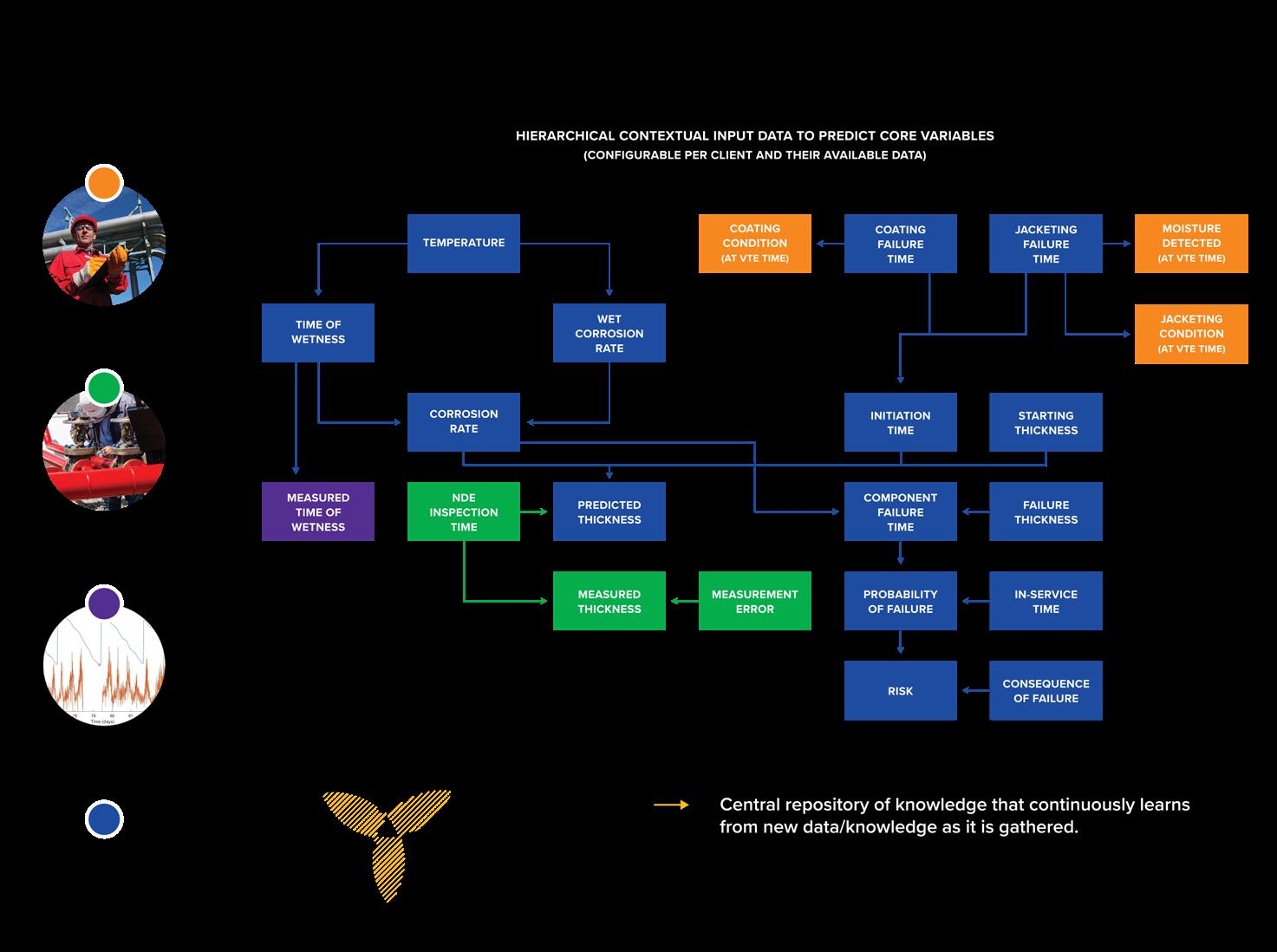
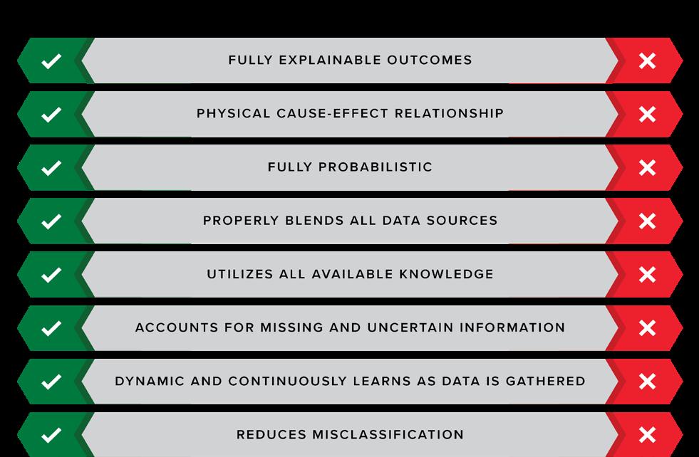
39 Handling CUI with explainable AI
Gordon Cope, Contributing Editor, discusses how the European fertilizer market has reacted to ongoing developments on the global stage.
14 Analysing the facts: gas analysis in fertilizer production
Maria-Katharina Mokosch, Servomex, the Netherlands, examines the role of gas analysis in fertilizer production and how it helps to reduce emissions while optimising processes for a more sustainable future.
19 Innovative energy recovery
Eduardo Almeida, Clark Solutions, Brazil, introduces innovative energy recovery solutions for existing sulfuric acid plants.
25 Suluric acid pump solutions
Hani Tello, ITT Rheinhütte Pumpen GmbH, Germany, considers important design features of pumps that convey hot sulfuric acid in high-temperature applications.
29 Mastering molten sulfur
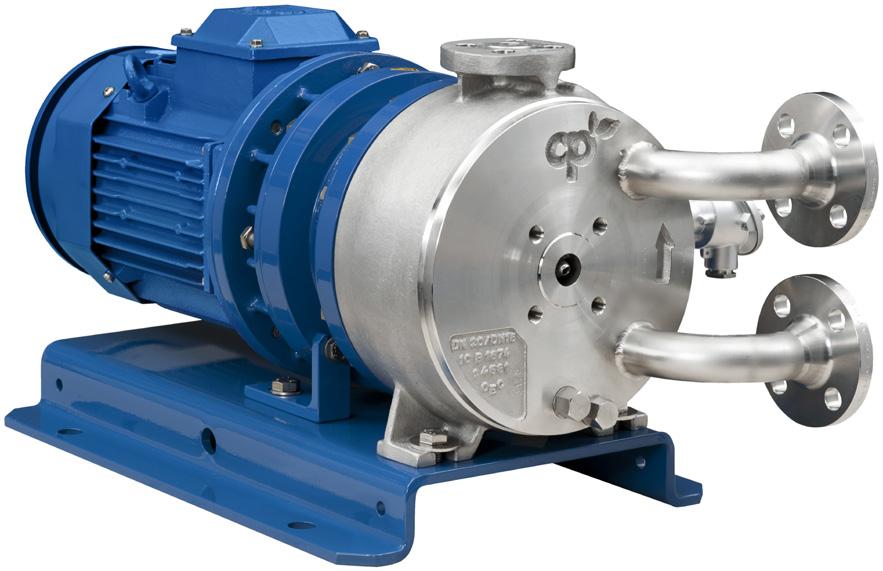
Joseph Acevedo, CP Pumps Inc., explores heated, sealless pump solutions for handling molten sulfur.
Charles Panzarella and Aaron Stenta, Equity Research, USA, assess how explainable AI can be used to solve problems with CUI in the fertilizer industry.
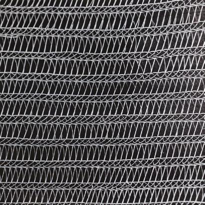
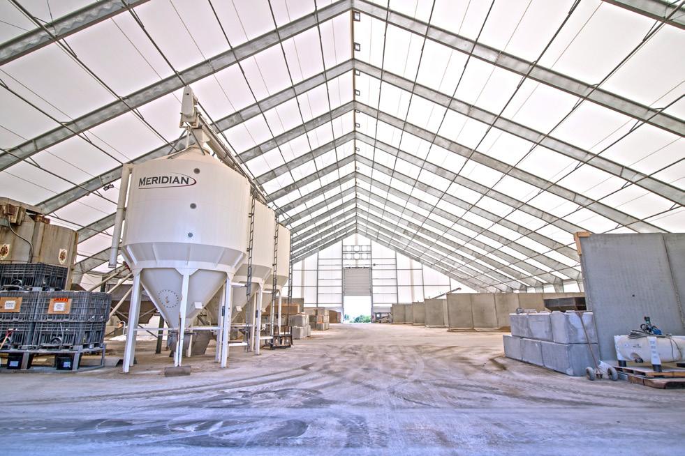
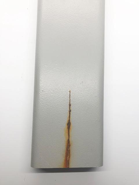
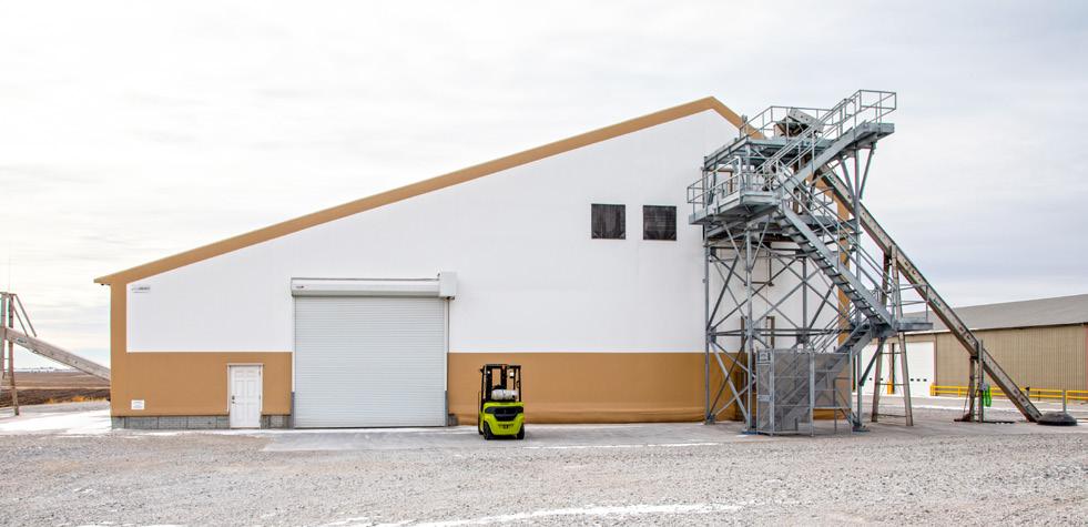
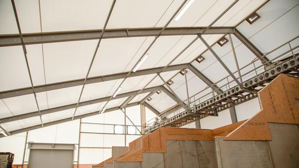
43 Waging war on facility corrosion
Paul Smith, Legacy Building Solutions, USA, explains how tension fabric buildings can offer excellent resistance to fertilizer’s corrosive attacks.
47 The heart of the matter
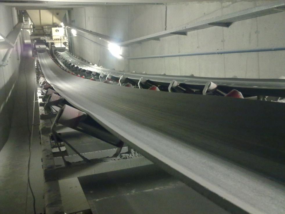
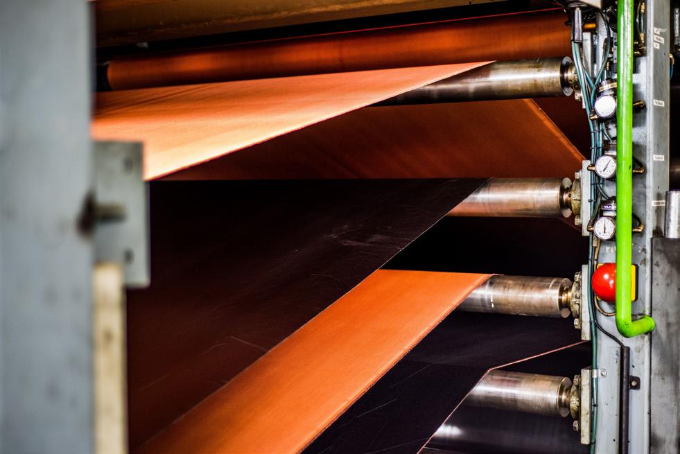
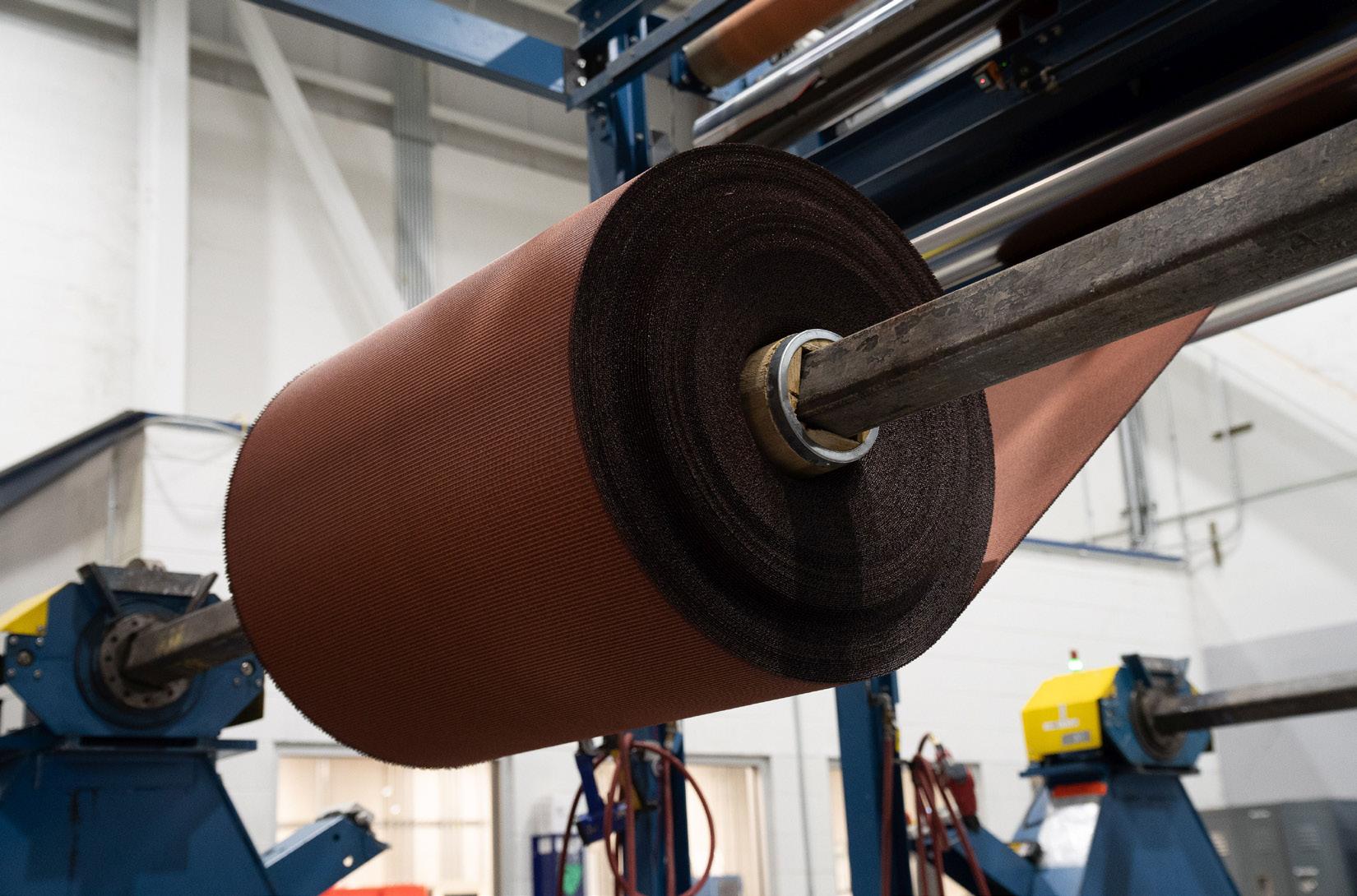
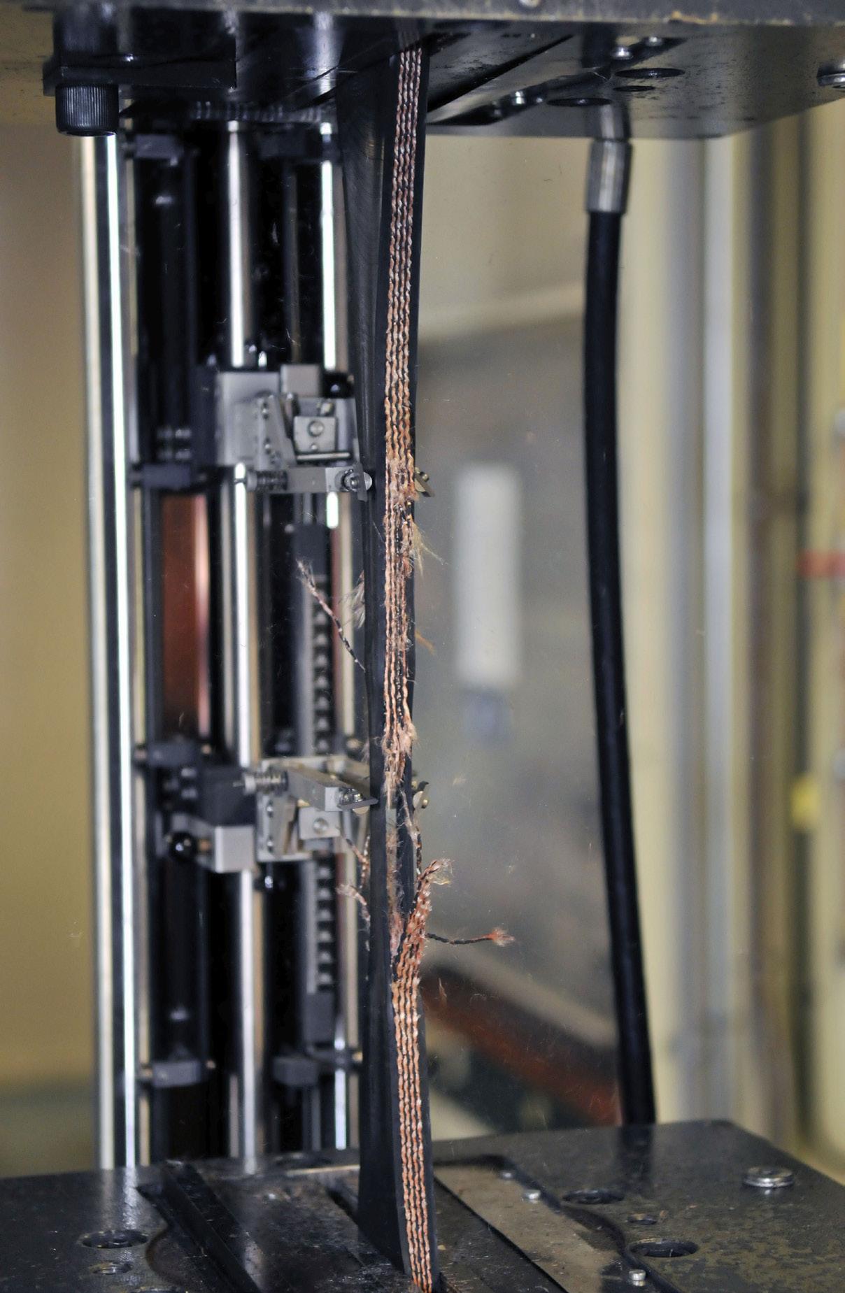
Leslie David, Conveyor Belt Specialist, details how deficiencies in the carcass of a conveyor belt can significantly reduce both performance and longevity.
52 Maximising yield, minimising output
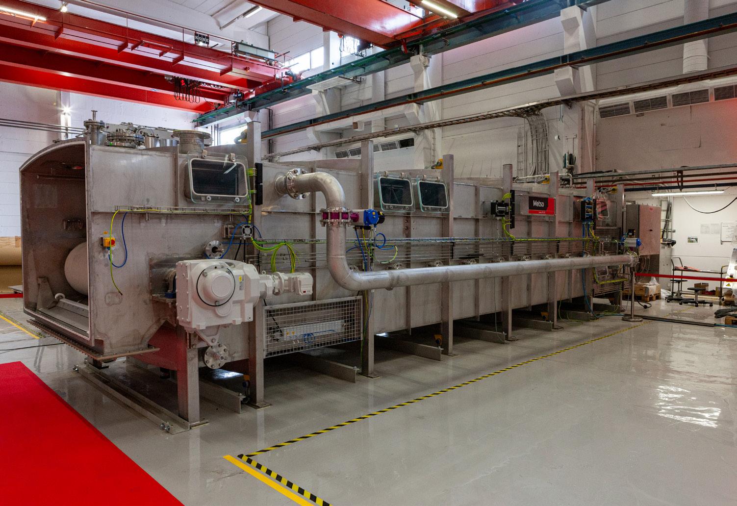
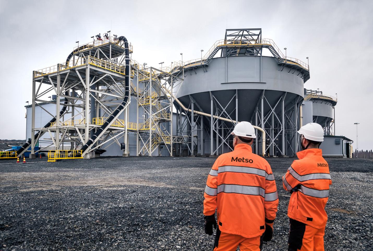
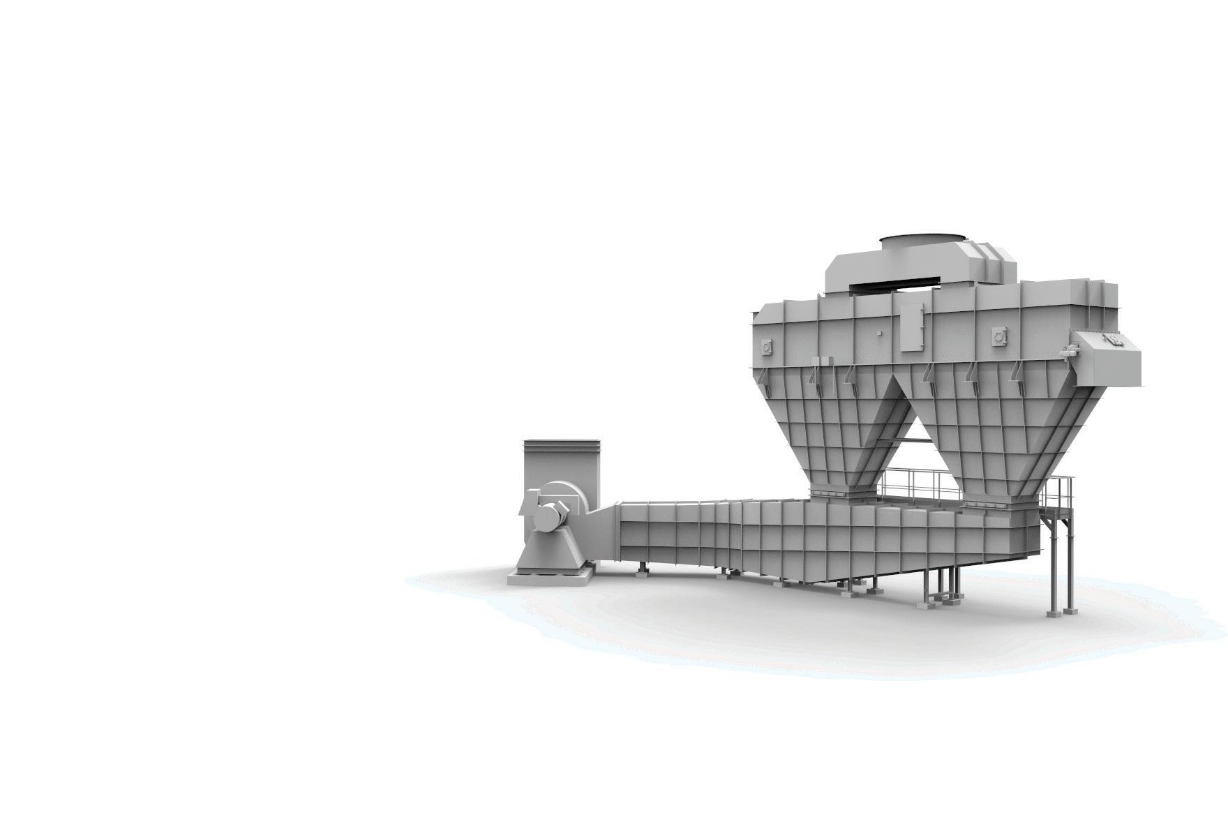
Subhashis Ghosh, Metso, analyses strategies that can be used to optimise fertilizer mining and processing.
CONTACT US
MANAGING EDITOR
James Little james.little@palladianpublications.com
Palladian Publications Ltd, 15 South Street, Farnham, Surrey GU9 7QU, UK Tel: +44 (0) 1252 718 999 Website: www.worldfertilizer.com
SUBSCRIPTIONS
(postage
year discounted rate: £80 UK including postage £96 (postage airmail).
Subscription claims: Claims for non receipt of issues must be made within 3 months of publication of the issue or they will not be honoured without charge.
Applicable only to the USA & Canada: World Fertilizer (ISSN No: 2398-4384, USPS No: PENDING) is published 8 times a year by Palladian Publications Ltd GBR and distributed in the USA by Asendia USA, 701 Ashland Ave, Folcroft PA. Application to Mail at Periodicals Postage Prices is pending at Philadelphia, PA and additional mailing offices. POSTMASTER: send address changes to World Fertilizer, 701 Ashland Ave, Folcroft, PA. 19032.
OLIVER KLEINSCHMIDT, DEPUTY EDITOR
Whether you love it or you hate it, Artificial Intelligence (AI) is here to stay.
The floodgates have been opened and across the globe industries are figuring out how to adapt to this new paradigm. Almost every industry has been trying to find a way to usefully implement AI to assist and enhance existing processes; the global agriculture industry is no different.
But what does this mean for the fertilizer industry?
For many it smells of opportunity. Already there are projects like Fertilizer AI which aims to demonstrate that the prediction of optimal fertilization timings and amounts using a short-term forecast is feasible. The project has even received funding from the EU’s European Research Council.1
The benefits of AI implementation in the fertilizer industry are clear. Most obviously, it can optimise production and distribution, utilising machine learning (ML) algorithms to improve data analysis and run simulations of potential, real-world scenarios. When developed for the purposes of predictive maintenance it can even be used to identify problems and faults at the earliest point possible. Tools like the US Department of Agriculture’s (USDA’s) Integrated Farm System Model (IFSM) makes use of ML to simulate runoff, leaching, and degradation of fertilizers.2 Moreover, AI can enhance the application of fertilizers in agriculture by calculating the most optimal distribution to maximise yield and by coordinating fertilizer deployment using drones and other automatic systems. Yara International has been working on this type of enhancement with its N-Sensor technology combining AI with drones and satellite imagery to make real-time adjustments to nitrogen-based fertilizer application.2 There is also the question of ecological impact and sustainability with AI having the potential to identify flaws in existing production and distribution systems that produce excessive carbon emissions and create significant amounts of waste.
But AI is certainly not without its flaws. At present there are limitations in the amount of comprehensive and accurate data available to AI systems which require accurate data to work effectively. The data that is accurate and available is not widespread and for agrarian nations, such as India, and that presents a real problem for furthering the implementation of AI in those markets. Without accessible data to input into these AI systems, they are hamstrung. Another, wide-reaching drawback is the direct ecological impact of AI. Data centres are at the heart of this problem. They are used to house and operate these AI systems and have a voracious appetite for electric energy and power; largely used for cooling systems that counteract the amount of heat that these sites give off. Data centres consume vast amounts of water and require crucial rare minerals in large quantities. AI currently requires an unsustainable amount of resources to operate.
AI is rapidly transforming how we approach challenges in the fertilizer industry – ushering in an era of agrochemistry more strongly supported by digital technologies. With new developments every day, AI could help enable smarter, more sustainable farming practices. The fertilizer industry needs to take advantage of this technology and use it as it has ultimately been intended, which is as a tool designed to assist humanity and make these processes easier.
A‘historic partnership’ to tackle the environmental impact and embrace the economic opportunities of fertilizers was launched on 10 September 2025 by the UK and Brazil.
Signed by UK Special Representative for Nature, Ruth Davis and Brazilian Deputy Agricultural Minister, Cleber Oliveira Soares, the memorandum of understanding (MoU) seeks ways to make fertilizer production more sustainable and efficient.
It includes increased collaboration on research and innovation, boosting supply chain resilience, and sharing best practices. This partnership comes as part of efforts to drive greater global co-operation of sustainable fertilizer production and use, showcasing the UK’s and Brazil’s global environmental leadership ahead of COP30 – where plans to boost the cooperation of governments and international organisations on fertilizers will be emphasised.
While fertilizers are beneficial for agriculture, they can cause significant pollution when overused and be a driver of climate change – being responsible for 5% of all global greenhouse gas emissions. It is therefore vital to optimise their use and increase efficiency wherever possible.
Ruth Davis said: “Global cooperation is vital to restore the health of our soils, protect nature, and guarantee food systems for future generations. Fertilizers are crucial for our food security, so it is vital that their production and use evolves in line with today’s environment and climate challenges.
“Brazil, host of COP30 and one of the world’s most biodiverse nations, has set an important example on tackling this vital issue. Together, we can unlock innovation, improve nitrogen management, and build resilience across landscapes and livelihoods.”
Cleber Oliveira Soares commented: “For Brazil, advancing sustainable practices in the use of fertilizers means combining the strength of our agriculture with the responsibility to protect biodiversity and natural resources.
“The Ministry of Agriculture and Livestock has been investing in research, innovation, and international cooperation to ensure that food production grows in an increasingly sustainable and efficient way. This partnership with the UK reinforces Brazil’s commitment to promoting solutions that reconcile food security, resilient supply chains, and the climate urgency we all share.”
THE NETHERLANDS Elessent acquires Sulphurnet
Elessent Clean Technologies (Elessent) has announced the acquisition of Sulphurnet, a provider of advanced filtration solutions based in the Netherlands. This investment supports Elessent’s mission to deliver comprehensive, innovative technologies that support cleaner, more efficient industrial processes worldwide.
Sulphurnet, a provider of sulfur processing technology as well as advanced filtration solutions, delivers outstanding impurity removal from sulfur feed streams – a critical process for optimising sulfuric acid production by ensuring reliability and maximising uptime. With a versatile lineup tailored to various operational needs, Sulphurnet’s offerings naturally enhance Elessent’s capabilities across the sulfuric acid, chemical, chlorine, and green hydrogen sectors.
“We are thrilled to welcome Sulphurnet to the Elessent family,” said Eli Ben-Shoshan, CEO of Elessent Clean Technologies. “This acquisition is a natural fit for both companies. It enhances our ability to serve our customers with a broader range of high-performance technologies and strengthens our global presence in key markets.”
Rotterdam, the Netherlands https://www.argusmedia.com/en/ events/conferences/
Global Hydrogen Conference 03 December 2025 Virtual https://www.globalhydrogenreview. com/events/global-hydrogenconference-2025/
SOLIDS Dortmund
18 - 19 March 2026
Dortmund, Germany
https://www.solids-recyclingtechnik.de/en/
The Fertilizer Show
25 - 26 March 2026
Tampa, Florida, USA
https://fertilizershow.com/
BRAZIL Verde AgriTech granted patent for fertilizer production technology
Verde AgriTech Ltd, a specialty multi-nutrient potassium fertilizer innovator, has announced that its subsidiary Verde Fertilizantes LTDA has been granted a Brazilian patent for its process.
The process produces powdered, granulated, or microgranulated mineral fertilizers enriched with biological additives; in addition, the product produced from this process is also protected under this patent.
The patent, granted by Brazil’s National Institute of Industrial Property (INPI) under the Ministry of Economy, covers a process that combines glauconitic siltstone – a sedimentary rock composed of silt-sized iron-potassium phyllosilicate minerals – with beneficial microorganisms, advancing sustainable fertilizer technology and strengthening Verde’s intellectual property (IP) portfolio.
The patented process enables the production of powdered, granulated, or microgranulated fertilizers by combining glauconitic siltstone with beneficial microorganisms through industrial spraying techniques. Unlike conventional fertilizer manufacturing, this innovation eliminates the drying stage, reducing production costs while preserving viability of beneficial microorganisms for up to 180 days.
PARAGUAY
Yara signs offtake agreement with ATOME
ATOME, a low-carbon fertilizer developer and the UK’s only international, industrial scale, low-carbon fertilizer company, has signed a definitive minimum 10-year offtake agreement with Yara International ASA for the sale, by ATOME, and purchase, by Yara, of the entire 260 000 tpy low-carbon fertilizer production, based on 100% renewable power, at the Villeta Project in Paraguay.
The agreement reflects the Heads of Terms entered into with Yara, as announced on 24 July 2024, to which investors are referred. The term of the agreement is 10 years with an option to extend. The term as well as the committed purchase nature for all of ATOME’s production underpins the long-term success and profitability of the Project, aligning all parties, underscoring the bankability of the project for lenders and validating ATOME’s business model.
USA Peregrine signs LoI with OCP Group
Peregrine Hydrogen has announced that it has signed a letter of intent (LoI) with OCP Group, a company which specialises in plant nutrition solutions and phosphate-based fertilizers, to secure scale-up funding and offtake for its hydrogen technology.
Peregrine is developing a novel electrolyser technology that co-produces clean hydrogen and sulfuric acid. In commodity industries, such as the fertilizer industry, cost competitiveness is key and has hampered adoption of green technologies. Peregrine’s dual production method is set to change that.
“Peregrine’s approach can deliver clean hydrogen at a significantly lower cost than existing methods,” said Matt Shaner, CTO of Peregrine Hydrogen. “Our partnership with OCP Group is a critical step toward deploying this technology at scale and accelerating decarbonisation in cost-sensitive sectors.”
Gordon Cope, Contributing Editor, discusses how the European fertilizer market has reacted to ongoing developments on the global stage.
ertilizer is extremely important to Europe, not only as a crop nutrient that greatly enhances food production, but also as a cornerstone to the continent’s economy. Fertilizers Europe estimates that the sector had a market value of US$43.4 billion in 2024. 1 Unfortunately, the sector has been facing major challenges for several years, with far-reaching consequences.
Prior to 2021, the EU produced approximately 13 million tpy of nitrogen fertilizers, 2.9 million tpy of potash, and 2.2 million tpy of phosphate products,
while consuming 11.2 million tpy of nitrogen, 2.6 million tpy of potash, and 2.6 million tpy of phosphates. The numbers look fairly well balanced on paper, but regional demand and other economic factors, such as transportation costs and blending, result in extensive imports; around 8 million tpy of fertilizers were sourced from Belarus, Russia, and Ukraine.
Potash
After the invasion of Ukraine by Russia in 2022, the EU exempted food and fertilizer from its wartime sanctions,
but payment restrictions complicated the movement of fertilizers from Belarus and Russia, both major potash exporters to Europe. Imports from Canada helped stabilise supply shortages, but long-term solutions (especially the development of domestic sources), are needed.
The EU has limited expansion potential for mining. Germany accounts for about 87% of EU production and the rest comes from Spain. Economic deposits in Germany are depleting and total ore production now stands at approximately 3.3 million tpy. The closest prospect for new production is the proposed Muga-Vipasca mine in Northern Spain. Highfield Resources estimates capital costs at €735 million; the mine has sufficient reserves to produce 1 million tpy of muriate of potash (MOP) for 30 years. Opponents to the project cite water concerns in the arid climate. Preliminary earthmoving is underway, but no production date has been set.
In the UK, Anglo American’s 13 million tpy Woodsmith polyhalite project in the Yorkshire region faces further delays. The underground mine involves digging 1.6 km deep mine shafts and a 37 km tunnel to transport raw material to the port of Teesside. The rock will then be milled into sulfate of potash-magnesia (SOPM) for export around the world. In May, 2024, Australian mining giant BHP offered £38.6 billion for the firm. During protracted negotiations, Anglo American reduced capital expenditures on the project and put much of the existing infrastructure into maintenance mode. The offer was eventually rejected by the board, but the slowdown has pushed the ultimate production date beyond 2027.
Phosphate
The EU has one active phosphorous mine producing approximately 900 000 tpy of phosphate ore, satisfying an estimated 10% of fertilizer demand. In 2024, Europe imported almost €4 billion in phosphorous fertilizer; approximately 35% came from Morocco. The North African country, which holds the world’s largest phosphate reserves, has recently increased capacity at its Jorf Lasfar Chemical Complex by 1 million tpy of granular phosphate, with further phases planned. Thanks to increased exports to Europe and Asia, phosphate miner OCP’s net profits for 2024 grew to US$9.76 billion, up from US$9 billion the year prior.
Over-reliance on imports creates risk, however, in addition to the cost, international sources leave European farmers vulnerable to price volatility, supply disruptions, and geopolitical upheaval.
Recycling phosphate holds significant potential. The European Sustainable Phosphorous Platform (ESPP) is a broad-based coalition dedicated to recovering phosphorous compounds. The EU generates over 800 000 tpy of phosphorous in sewage, animal by-products, and food scraps. When sewage sludge is incinerated, the fly ash contains up to 11% phosphorous compounds. Since 2019, fertilizer producer ICL has been recycling phosphates from municipal waste streams at its Amfert fertilizer plant in the Dutch Province of Noord-Holland. The recycled mineral displaces approximately 10% of the mined phosphate feedstock at ICL’s fertilizer plant; the company has the goal of eventually reaching 100% recycled phosphate.
Exploration for phosphate in the EU has resulted in a game-changing discovery. In July, 2023, Norge Mining announced that it had delineated 70 billion t of high-quality phosphate igneous rock in Southern Norway, sufficient to meet global demand for fertilizer, EV batteries, and renewable power storage for decades to come. ABB, an international engineering firm, is conducting a front-end engineering and design (FEED) study; the goal is to build a completely-electrified mine, with a tentative start up date of 2028.
Ammonia
Even prior to the Russian invasion of Ukraine, Europe’s ammonia sector was in dire straits. Natural gas price spikes in Europe in late 2021 increased feedstock and energy costs to the point where 70% of the continent’s capacity was temporarily shuttered. The invasion in 2022 did little to alleviate pressures; it was not until early 2024 that temporary closures fell below 20%.
The damage had been done, however, companies began permanent cessation of manufacturing operations; first at CF’s Billingham site in the UK, then Yara’s 400 000 tpy plant in Tertre, Belgium. BASF Chemicals also announced that it would be closing German plants and offshoring its ammonia manufacturing.
The reasons are multifold. First, natural gas price volatility makes it difficult to compete with lower-cost competitors; European manufacturers routinely face feedstock and energy costs 10 times that of North America. Secondly, strong unions drive up labour wages, a significant cost in Europe.
The third factor is environmental regulation and low-carbon goals. In addition to curbing pollution, the EU has set stringent net zero targets for a large swath of the economy. The Renewable Energy Directive III (RED III), requires fertilizer plants to replace 42% of grey hydrogen with green hydrogen by 2030 and 60% by 2035. While cost-equalising legislation helps protect European producers from competitors in more lax jurisdictions flooding the domestic market, it does nothing to address export competition.
Ammonia manufacturers and governments are well aware that the loss of domestic production means farmers are increasingly exposed to international risk, and the sector is working on several options to mitigate threats. Plans include building carbon capture and storage (CCS) systems to reduce plant emissions, and sourcing low-carbon hydrogen created by electrolysis from both European and offshore production (the Billingham and Terte plants, for instance, will maintain local supplies for farmers by importing ammonia).
Finally, producers are looking to establish plants in jurisdictions where they can create low-carbon ammonia on large scale plants. Yara has been conducting FEED at a potential site in Corpus Christi, Texas, US, where it would produce up to 1.4 million tpy of blue ammonia. OCI Global partnered with New Fortress Energy to purchase green ammonia from the latter’s plant in Texas; the hydrogen would then be converted to as much as 160 000 tpy of green ammonia for export to the European market. Germany’s RWE has plans to build a low-carbon ammonia
complex in Texas that would produce up to 10 million tpy of blue and green ammonia for export to Asia and Europe.
Problems
In spite of EU subsidies and market protection, green ammonia is facing a lack of demand from large industrial users. The primary reason is price; due to a recent spike in the cost of electrolysers, the cost of green ammonia is expected to remain 2 - 5 times higher than grey ammonia until the mid-century, and manufacturers who cannot find alternative feedstocks are reluctant to place themselves at a market disadvantage. Credits and subsidies can encourage demand, but until expected technology gains bring production prices down to parity, take-up will be limited. Within the agricultural sector, farmers who are unwilling to pay a premium to meet carbon-reduction quotas will likely cut back on applications, reducing yields.
The second is the cost of infrastructure. Analysts reckon that building the new hydrogen economy in Europe will require hundreds of billions of dollars. Creating a pipeline network in Germany alone to handle green hydrogen is calculated at approximately US$23.6 billion, and another US$23 billion to build offshore wind farms to generate enough to meet 15% of the estimated hydrogen-production consumption in 2050.
Thirdly, designing an entirely new ammonia-manufacturing process is fraught with complications. Over the last century, conventional ammonia plants have been engineered to prioritise the reliability and stability of chemical and energy inputs and processes in order to optimise output. Creating green ammonia requires renewable-energy application to three inputs; creating pure green hydrogen through electrolysis, removing nitrogen from the atmosphere through cryogenics, and synthesising ammonia in a converter.
Because renewable energy from wind and solar fluctuates hourly, daily, and seasonally, the primary challenge is to create a plant that can handle flexibility and resilience. Ammonia converters need to be designed and built using materials that can handle robust variations so as not to lead to equipment failure. Catalysts must also be customised; iron-based catalysts are excellent for traditional ammonia plants, but may not necessarily be the best for green ammonia plants. Non-iron based catalysts have been tested, but are not as readily-available.
Faced with lack of demand and a bewildering array of regulations, untried technology, and market uncertainty, plans for green hydrogen infrastructure are being cancelled or put on hold throughout Europe. In September, 2024, Shell, citing lack of market demand, withdrew plans to build a low-carbon hydrogen plant on Norway’s west coast. That same month, Equinor also announced that it would not build a pipeline designed to carry up to 10 GW of blue hydrogen from Norway to Germany, citing a dearth of customers and uncertain regulatory framework. In October 2024, Spain’s Repsol announced that it would pause 350 MW of electrolysis capacity in its home country, due to tax policy and demand concerns.
Offshoring green ammonia production to North America also faces difficulties. During the
Biden Administration, the Office of Clean Energy Demonstration had awarded US$3.7 billion to 24 green energy projects to help companies develop new technologies that reduced carbon emissions. In June 2025, the Trump administration cancelled those awards. Now that the White House and Congress are controlled by Republicans, the loss of further subsidies (including up to US$3/kg for green hydrogen in Biden’s Inflation Reduction Act), could make most low-carbon projects in the US economically non-viable; a last-minute, two year extension in the Trump Administration’s latest 2025 budget provided only temporary relief.
The future
In the near term, the EU’s agricultural demand for potash and phosphate will be met by increased imports from international sources. In the longer term, diplomatic solutions to the Ukraine war may see the lifting of economic sanctions, allowing potash to once again flow freely from Belarus and Russia. The discovery of immense phosphate deposits in Norway will also result in a reliable new domestic source by the end of the decade.
For ammonia, the growth in non-agricultural uses will dominate the sector. Marine transportation holds special promise. In April 2025, the International Maritime Organization (IMO) established a legally-binding framework to reduce greenhouse gas (GHG) emissions across the global shipping sector to net-zero by 2050. The new measures, which will come into force in 2027, encompass new fuel standards for ships over 5000 t as well as a global pricing mechanism. Essentially, 80% of ships handling international shipments will be required to either reduce their annual GHG fuel intensity (GFI) – a measure of how much GHG is emitted for each unit of energy used – or purchase offsetting credits.
Fortunately, internal combustion engines (ICE) can easily be converted to consume green ammonia. Rystad Energy, a consultancy, predicts that, by 2035, there could be over 170 marine export terminals focusing on converting hydrogen into clean ammonia for use in marine transport vessels. Rystad estimates that this market could create over 50 million tpy of new demand by 2035, and up to 100 million tpy of demand by 2050; much of that demand will be met by producers near Rotterdam and other major European ports.
Conclusion
In conclusion, the EU will continue to seek innovative solutions to meet fertilizer demand. The development of domestic sources of phosphate and potash will significantly reduce the risk of sourcing international supplies, and the growth in new uses for ammonia in the marine transportation sector will be an incentive to preserve production on the continent. The European fertilizer sector has proven itself to be innovative and responsive, and will continue to thrive over the coming decade.
Reference:
1. ‘Fertilizer Industry: Facts and Figures’, Fertilizers Europe , (2023), https://www.fertilizerseurope.com/wp-content/ uploads/2023/07/Industry-Facts-and-figures-2023.pdf
Maria-Katharina Mokosch, Servomex, the Netherlands, examines the role of gas analysis in fertilizer production and how it helps to reduce emissions while optimising processes for a more sustainable future.
ithin agriculture and global food production, agrochemicals such as fertilizers play a critical role in facilitating the growth of crops and plants. By providing the right nutrients to the soil, fertilizers nurture crops to grow bigger and quicker, ready to be transported to supermarkets and into homes.
Faster-growing and higher-yielding crops are rising in importance because of the rapidly growing global population, which also means the demand for food is growing quickly.
Alongside an increasing population, the agricultural and food production industries face climate pressures; they are expected to reduce emissions and their usage of resources. All of this leads to a call for more efficiency and sustainability within these industries. Fertilizer production is no exception.
As fertilizer production scales up, the role of gas analysis becomes increasingly critical. It delivers three key benefits: safeguarding personnel and surrounding environments, optimising process efficiency, and enabling accurate emissions monitoring to support cleaner, more sustainable operations.
A process built on gas reactions
At the heart of fertilizer production are chemical reactions between gases. This is especially the case when manufacturing nitrogen-based fertilizers, which utilise ammonia (NH3).
NH3 is a key ingredient in the production of these nitrogen fertilizers, with production using 80% of global ammonia supplies.1 However, to get this active ingredient, several chemical reactions must take place. At the very beginning of the production process, methane (CH4) is separated into hydrogen (H2) and carbon dioxide (CO2) molecules through a reaction with water (H2O). From here, the H2 is combined with nitrogen (N2) to form NH3. However, this process is slightly more complex, as carbon monoxide (CO) and CO2 are both resulting products of the reaction.
Following the reformers, the feed undergoes a CO shift reaction, which converts the more dangerous gas, CO, to a safer gas, CO2. From here, the resulting product goes through a CO2 wash, removing the CO2 from the feed, leaving N2 and H2
The two pure gases are finally sent through a reactor, where a chemical reaction between them produces the NH3
Finally, the production of fertilizer can start. The NH3 goes through another reactor, where it is combined with CO2 before being dehydrated to form urea (CH4N2O). Alternatively, ammonia is oxidised with air to create ammonium nitrate, which is used for nitrogen fertilizers. Throughout all these gas-phase chemical reactions, process composition, purity and safety are paramount.
Not only will these ensure process safety, but also the quality of the product.
The role of precise gas analysis
Gas analysis and monitoring allow managers to control processes and monitor the quality of the feed, maintaining consistency throughout the production process. Accurate and continuous monitoring also plays a part in ensuring processes are functioning as efficiently as possible, working to reduce waste by-products and energy consumption, and supporting compliance with local environmental regulations.
Several types of gas analysers are typically used in the production of agrochemicals, such as fertilizers, specifically at the beginning of the process where ammonia is being made.
During this process, rugged liquid and gas analysers are placed before and after several of the stages, such as the reformers, the CO shift, the CO2 wash, and before the ammonia and urea reactors.
Quality assurance
Monitoring gases going into reactors where chemical reactions will take place is important because it allows operators to check the quality of gases at each stage. This is often done by measuring the level of impurities within the gas, making sure they are as low as possible.
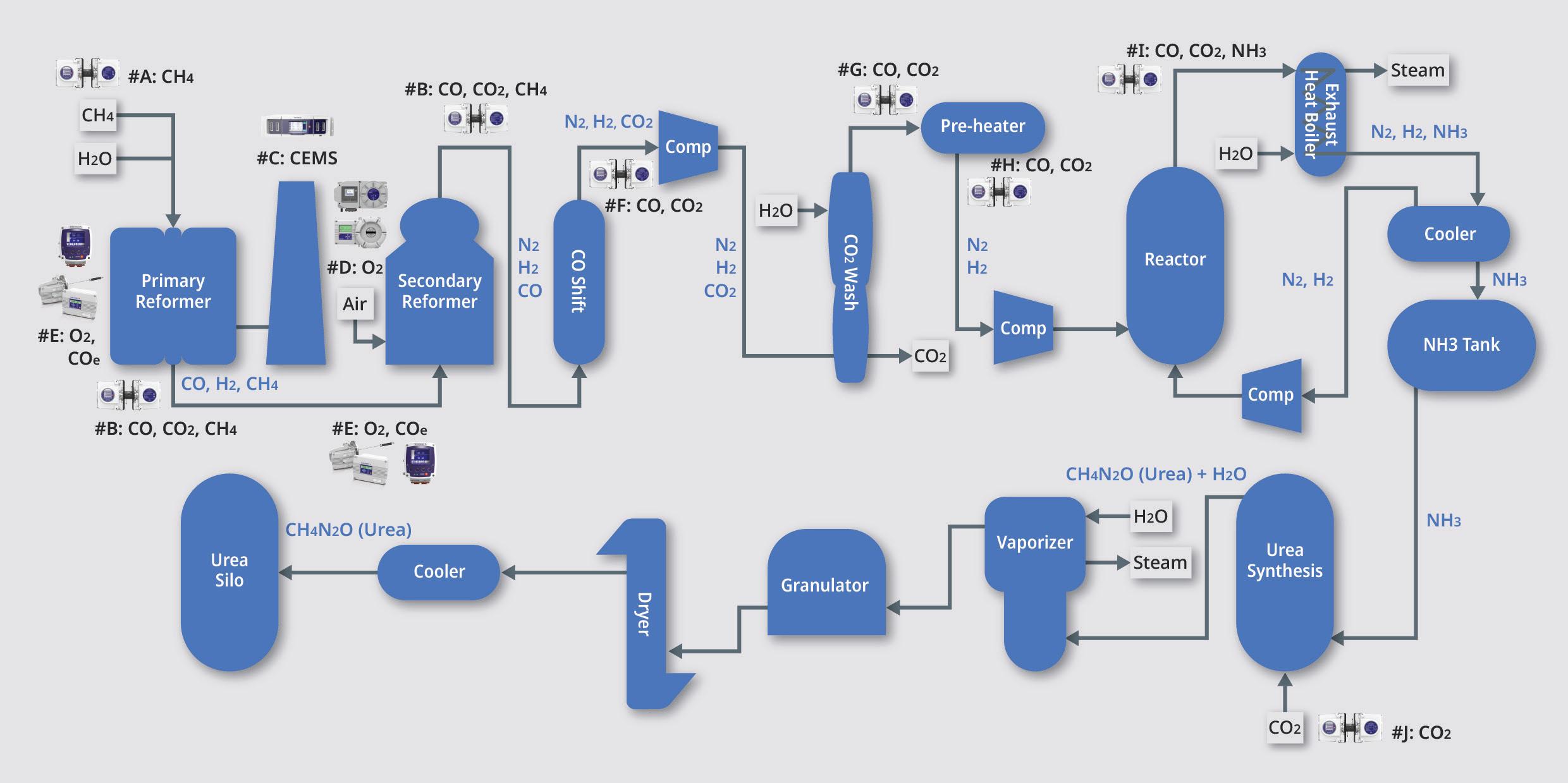
At the start of the process (see Figure 1) an analyser is used to measure the quality of methane that is used to produce hydrogen. In this situation, the analyser is required to measure 100% methane, ensuring the quality of the feed.
At the same measurement point, another gas analyser is placed near the secondary reformer, monitoring the purity of O2 being used to promote the production of pure hydrogen.
Further along the process line, an analyser is placed after the CO2 wash and before the preheater, as well as after the preheater (Figure 1). At this stage, the analysers are measuring the level of impurities within the produced nitrogen and hydrogen, as little CO and CO2 as possible is required because they prevent the reactions needed to create ammonia and urea.
Therefore, an analyser after the CO2 wash typically measures between 0 - 1% of both CO and CO2, while the analyser after the preheater will measure a range from 0 - 20 parts-per-million (ppm) of CO and 0 - 25 ppm for CO2. Monitoring the impurity levels at this stage of the process helps operators detect the presence of excessive levels of these gases early to create a pure product further down the line.
The last quality check takes place at the urea synthesizer (Figure 1), where the CO2 entering the process is measured to ensure it is of a high enough standard to produce quality urea for fertilizer.
Process control
During the production of fertilizers, gas analysers are also used to control the process. As regulations tighten around emissions and an increasing requirement for energy sustainability, ammonia production plants now need data to help inform process optimisation and control.
Gas analysers are positioned between the two reformers, after the CO shift and after the ammonia synthesiser reactor (see Figure 1) to gain accurate and reliable data on the levels of CO, CO2, and CH4. The analyser will measure between 0 - 10% CO and CO2 after the primary reformer to make sure no excess by-products are being produced. These gases will need to be removed before the synthesis loop; therefore, an excess of each gas leads to increased energy consumption.
An analyser is typically used before each reformer, too (Figure 1), measuring oxygen levels between 0 - 21% and carbon monoxide equivalent (COe) between 0 - 2500 ppm. This monitors combustion efficiency, so operators do not over or underuse the gases needed for the reaction to take place.
Further down the line, after the CO shift and CO2 wash, the analyser will measure between 0 - 1% or 0 - 5% of CO (depending on the temperature of the shift) and 0 - 30% CO2 Again, operators can ensure processes are efficient and do not produce extra by-products.
After the ammonia synthesiser reactor, CO and CO2 are measured between 0 - 20 ppm, and ammonia is measured between 0 - 5%.
By monitoring these gases throughout the process, operators can adjust operations for optimal output, reducing energy usage across several stages of the production line.
Emissions monitoring
A final use of gas analysis within ammonia production for fertilizers is to continually monitor emissions produced from the reformer process. Continuous emission monitoring (CEMs) analysers will sit in the stack (Figure 1) measuring gases that are regulated in the area. This usually will be NO, CO, and O2
By monitoring these emissions, operators ensure compliance with local and industry regulations, which is a growing demand within the fertilizer industry.
All monitoring leads to safety
While each analyser at each stage of the ammonia production process achieves a specific task, such as quality control or emissions monitoring, they all work towards providing a safer, more efficient process with higher yields.
An analyser in practice
Ammonia production relies on accurate and reliable data to ensure optimum efficiency, safety, and emission control. Servomex provides several analysers that cover gas analysis throughout the whole ammonia production process. Their gas analysis empowers operators to adhere to local regulations and ensure safe, efficient operations.
The SERVOTOUGH SpectraExact 2500F has been designed for high-performance process monitoring, making it ideal for use across most of the measurement points in the production line.
As the analyser is certified to be used in hazardous areas, it is suitable for measuring O2, CO, and CO2 produced throughout the ammonia production process.
Using non-depleting infrared photometric technology, the analyser provides accurate, reliable, and real-time analysis of the key gases within ammonia production. This means operators can better control combustion processes, optimise processes and reduce emissions.
Additionally, the technology used means the analysers are low maintenance, reducing running costs and planned downtime for servicing and maintenance.
Driving sustainability in a high-emission sector
The production of fertilizers is very carbon-intensive, especially ammonia synthesis. This is why the industry is facing an increase in demand to reduce emissions and energy consumption.
Figure 1. The ammonia process.
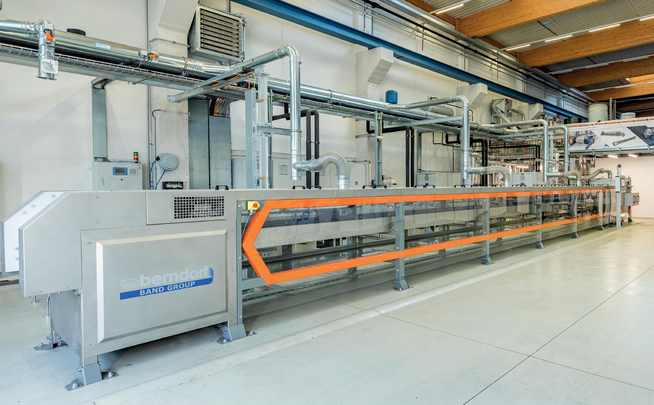
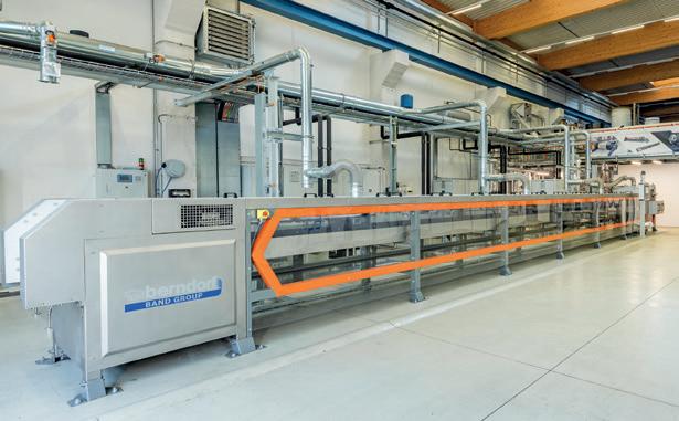
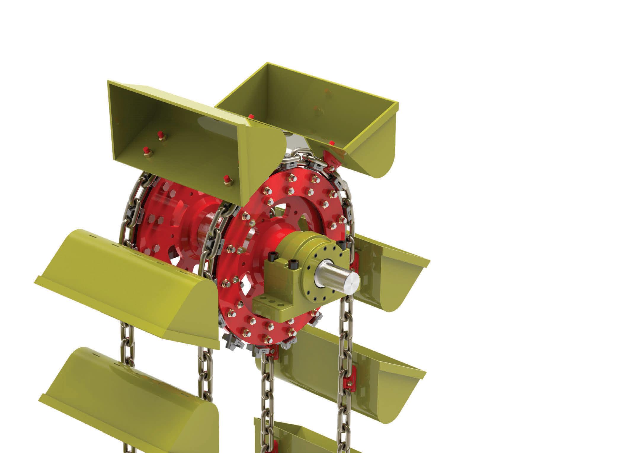
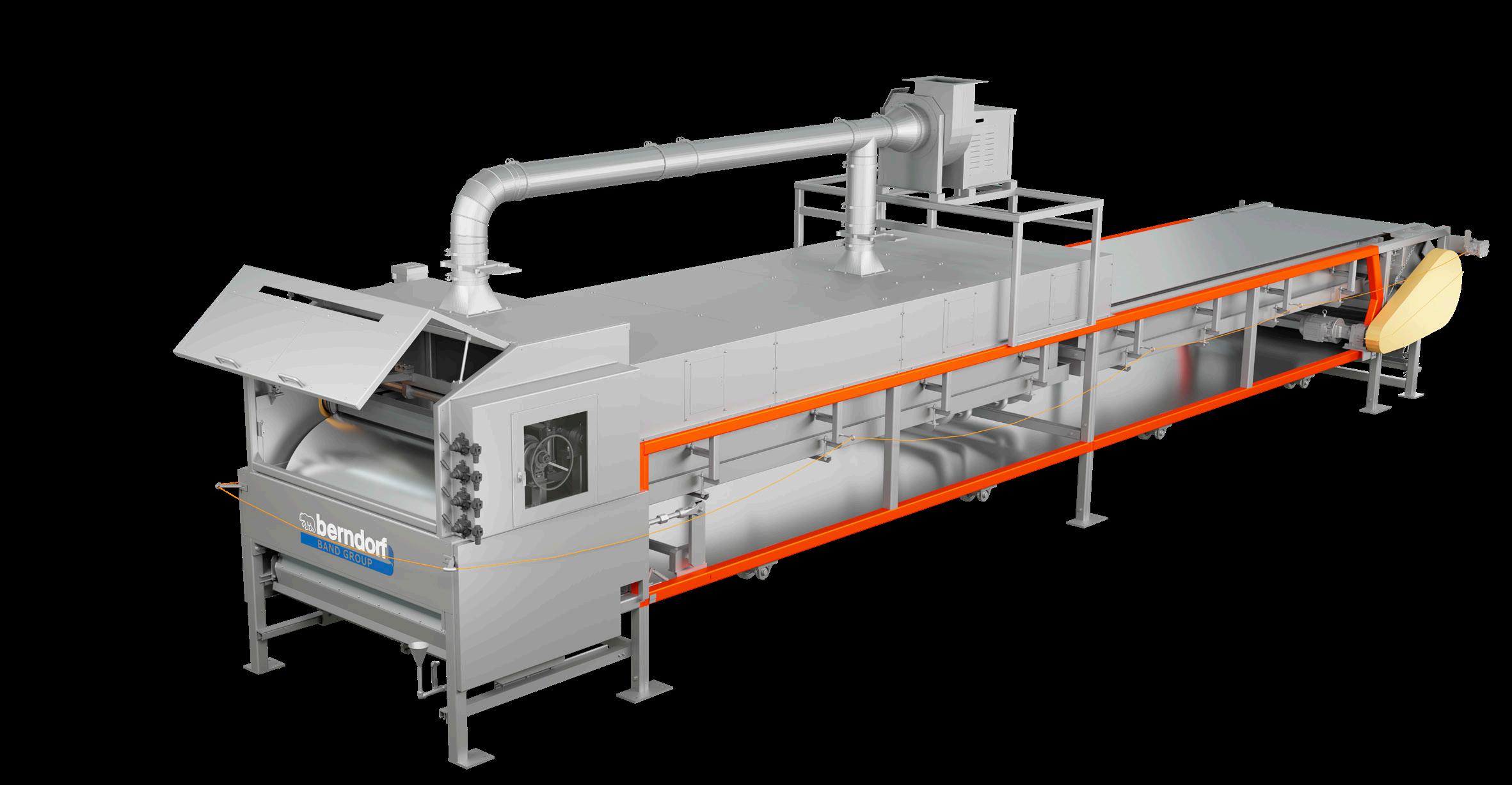
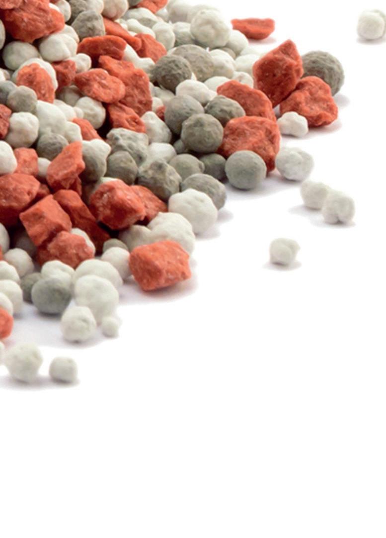
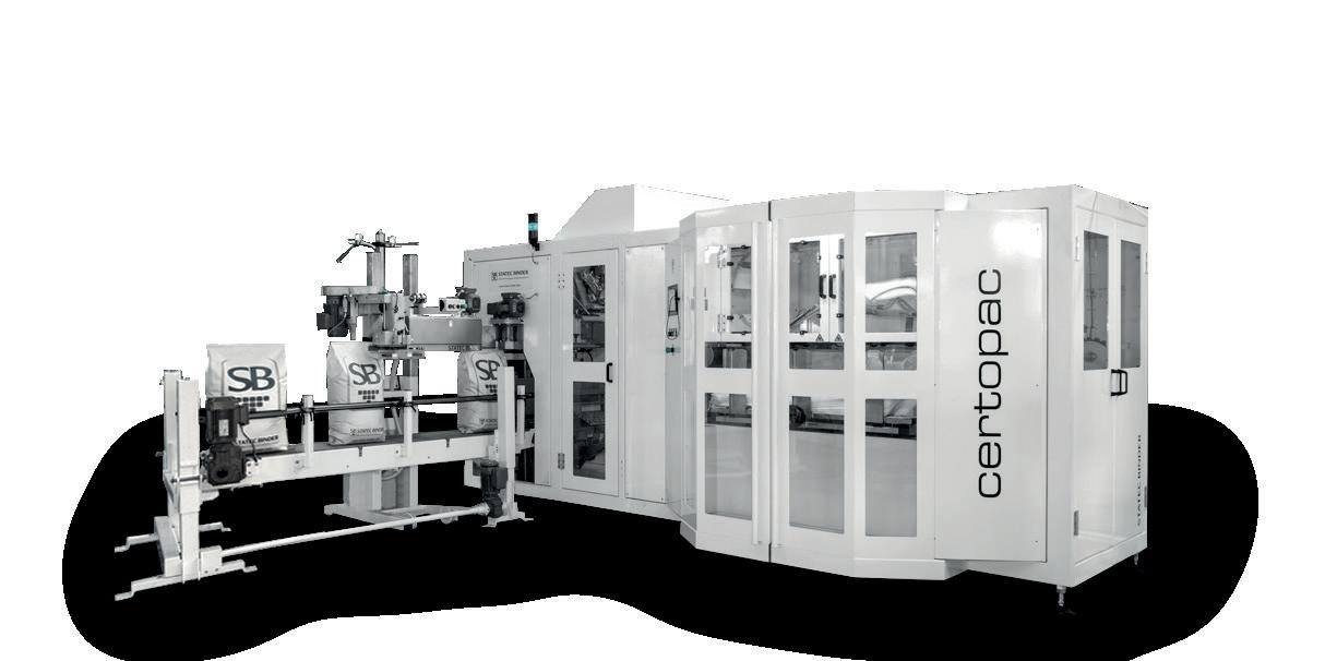
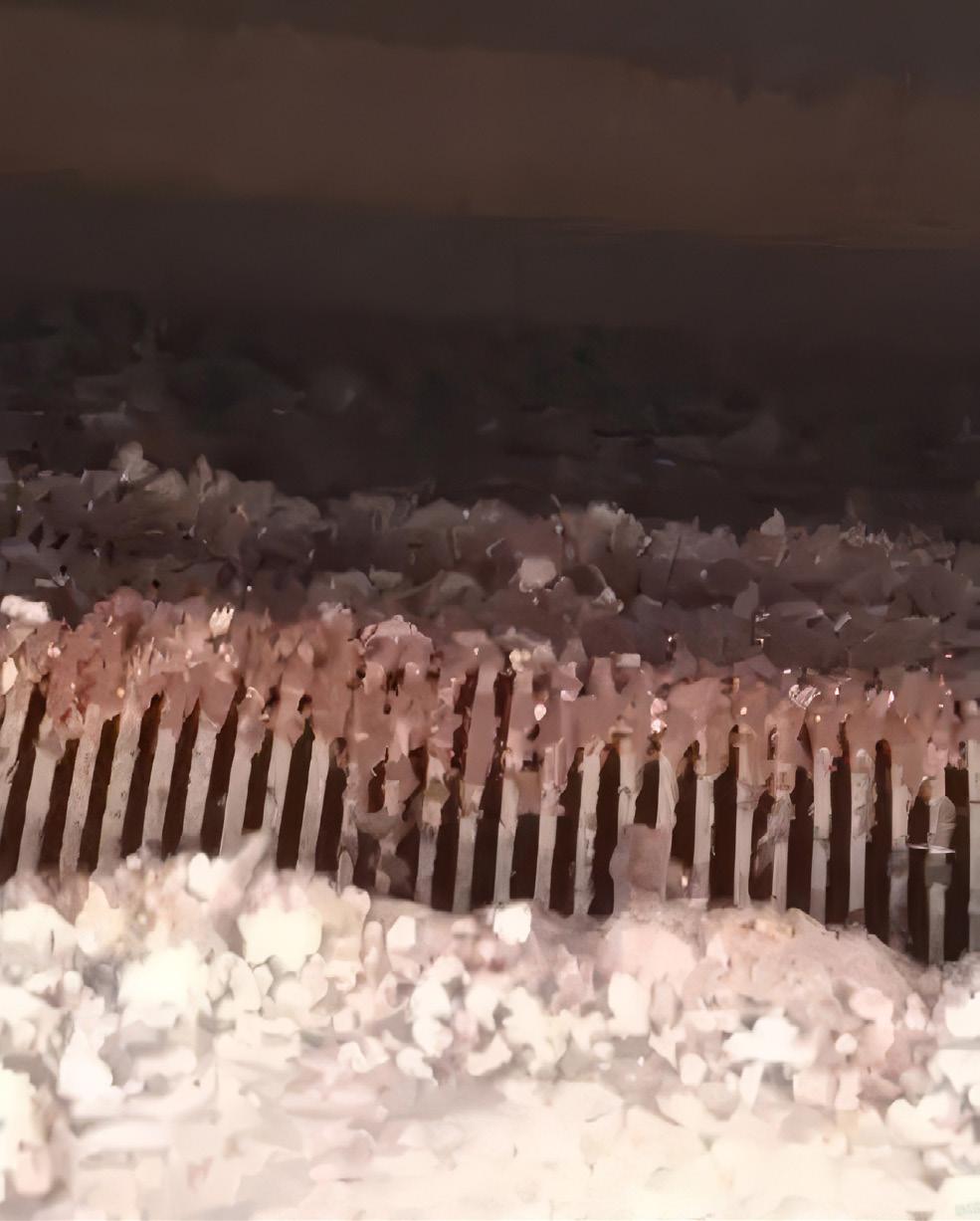
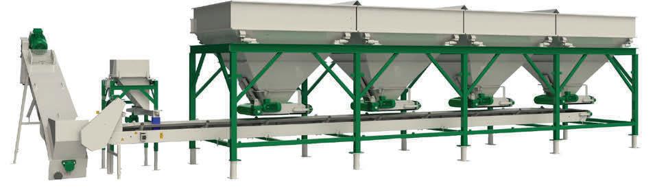
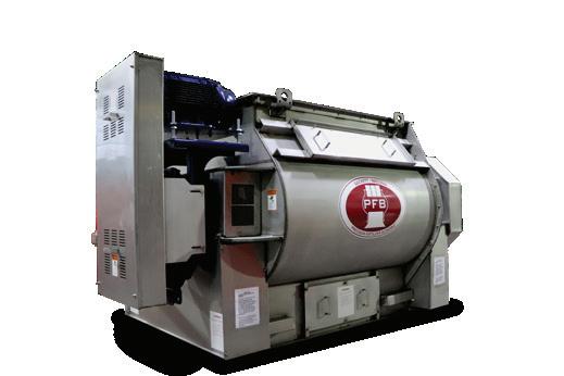
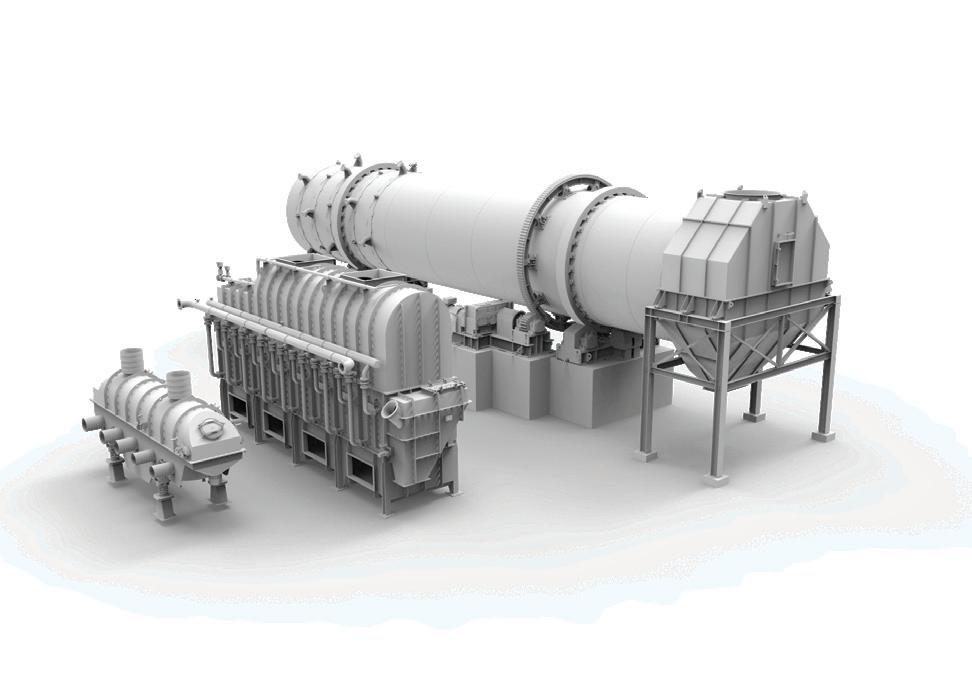
PREMIUM FORMING OF SULPHUR BENTONITE PASTILLES
Solidification & Cooling Systems
Special feeding devices for producing uniform drops of sulphur bentonite
High-quality and corrosionresistant Steel Belts for optimum heat transfer & belt run
+100 Machines in operation
Machine design that allows for switching between producing sulphur & sulphur bentonite
Project specific scope from Pastillator & Steel Belt Cooler to complete engineering package for up- & downstream
Table 1. Measurement points
Location Process
A CH4 feed
B Primary and secondary reformer
CH4, 0 - 100%
CO, 0 - 20%
, 0 - 20%
, 0 - 20% (primary)/CH4, 0 - 1% (secondary)
Quality SpectraExact 2500
Control SpectraExact 2500
C Stack (continuous emission monitoring system) Depends on regulation (NO, CO, O2) Emission 4900 Multigas
D Air feed O2, 0 - 21%
E Primary and secondary reformer O2, 0 - 21%, COe, 0 - 2500 ppm
F Shift reduction – high temperature (CO shift)
Quality Oxy/OxyExact
Combustion efficiency FluegasExact 2700 Laser 3 Plus
Control SpectraExact 2500 Shift reduction – low temperature (CO shift)
Improving gas analysis in fertilizer production helps plants meet these new demands in three ways.
The first is through helping reduce energy consumption. Data from the SpectraExact 2500F on the CO2 and CO levels from the reformers allows operators to optimise the reformer process so that the right amount of energy is used further down the line to remove these gases, ready for urea synthesis.
The second is minimising CO2 and nitrogen oxide (NOx) emissions. This is achieved through using CEMs solutions, such as the SERVOPRO 4900 Multigas analyser, to monitor greenhouse gases (GHG) produced from the reformers. Operators can use this data to adapt their processes and reduce emissions going forward.
The gas analysis ensures a quality product, reducing the chances of low-quality products and waste at the end of the production process.
Together, these make the process more sustainable for the future, reducing the use of carbon and decreasing the carbon footprint of the industry.
Enabling compliance and cleaner practices globally
Additionally, fertilizer plant operators are under pressure to comply with tightening global regulations and cleaner practices.
Places such as the EU, US, and Asia are implementing strict emissions control through ever-changing rules and regulations.
Gas analysers ensure operations are compliant with local standards without sacrificing productivity. Analysers must meet standards such as:
n ATEX in Europe.
n IECEx international standards.
n Northern American hazardous area approvals.
Control SpectraExact 2500
Quality SpectraExact 2500
Quality SpectraExact 2500
Control SpectraExact 2500
Quality SpectraExact 2500
This means the analyser is certified to meet regional requirements, across several global sectors, in measuring a continually flammable sample.
Sustainability and global impact
With agrochemical production estimated to expand from approximately 240 million t in 2023 to nearly 290 million t by 2030, any emissions reduction will impact the global environment.2
Process efficiency will lead to lower energy usage within the industry, decreasing the carbon footprint. It will also reduce emissions produced from the process, aligning with decarbonisation efforts and net-zero goals, enabling cleaner production.
Implementing reliable gas analysis will also support the sector’s continued transition towards more sustainable practices, furthering environmental impact reductions and longevity of the process to keep up with the growing demand for fertilizers to meet the growing global population’s needs.
A small sensor but a global impact
It can be said that the production of ammonia feeds the world; however, it heavily relies on chemical reactions between gases, creating a hazardous process that is carbon-intensive and contributes high quantities of greenhouse gases.
Gas analysers play a vital role in minimising these risks, keeping people and processes safe.
The data provided by gas analysers facilitates optimisations within the process for cleaner, efficient, and safer production that supports global food production.
Industry development requires configurations emphasising circularity and energy optimisation, with sulfuric acid plants having immense potential. Modern sulfuric acid plants can easily integrate with other facilities, while enabling Eduardo Almeida, Clark Solutions, Brazil, introduces innovative energy recovery solutions for existing sulfuric acid plants.
low-emission production, virtually no effluents, and high energy recovery – key aspects in a contemporary world grappling with climate change while demanding technological and sustainable progress.
Despite this goal, many sulfuric acid plants around the world disregard the energy potential of sulfur trioxide absorption. The reason for this is noble: prioritising safety. Energy recovery systems operate with higher pressures on the water side than on the acid side, promoting dilution, heating and autocatalytic corrosion in the event of a heat exchanger leak, which carries the risk of explosion due to the formation and entrapment of hydrogen. However, technologies like SAFEHX, a three-fluid heat exchanger that physically separates acid and water even in the event of a leak, enable energy recovery without compromising safety.
Although the significant economic and sustainable returns make it advantageous, adapting a plant without energy recovery to harness heat from sulfur trioxide absorption in the typical configuration can be challenging. This process often requires considerable layout changes, modifications to existing equipment, the addition of new equipment, operational
condition changes, and extended shutdown periods. For some specific plants, these changes may be financially or strategically prohibitive even though the payback is attractive.
This article presents one of many possible alternative configurations to simplify the implementation of energy recovery in sulfuric acid plants, while still delivering substantial results.
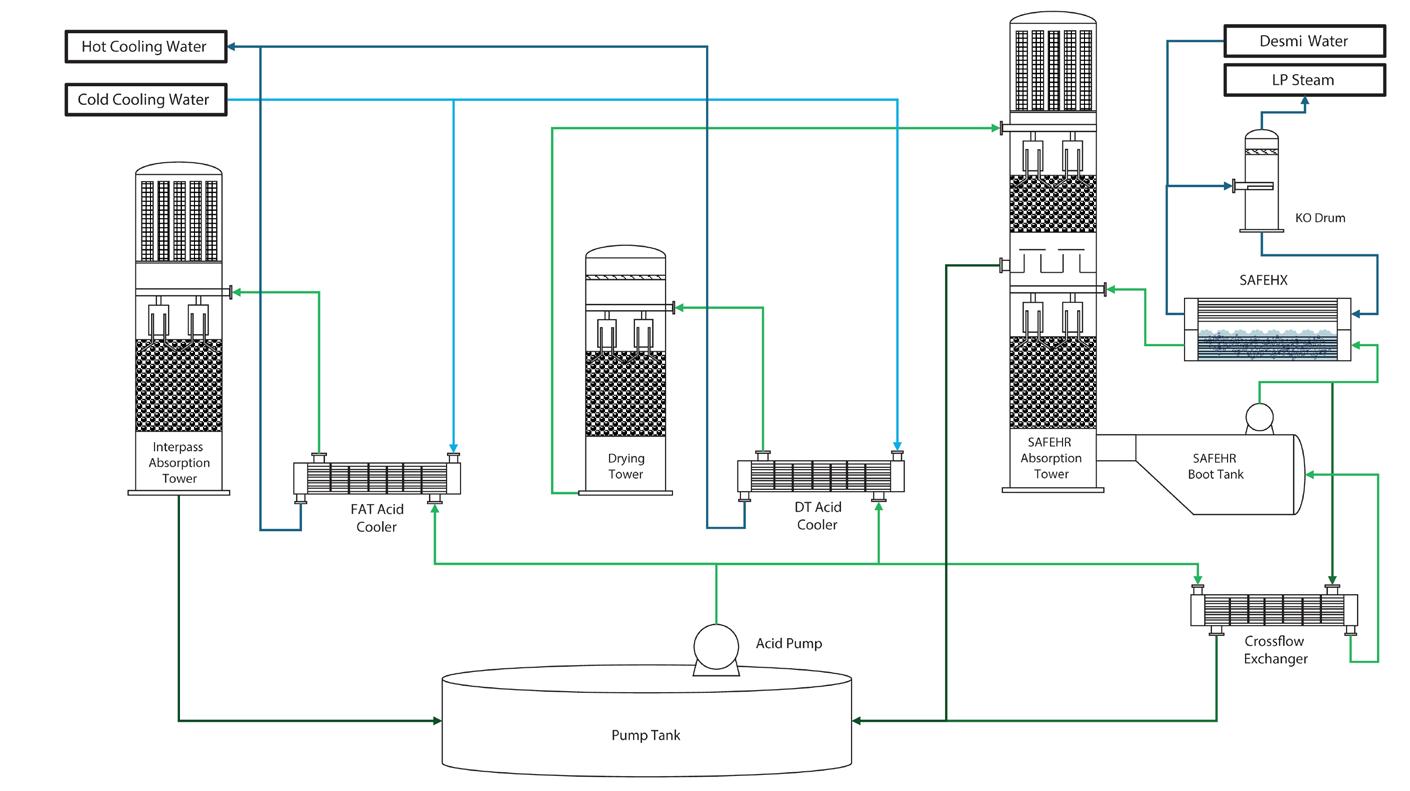
Standard acid heat recovery setup
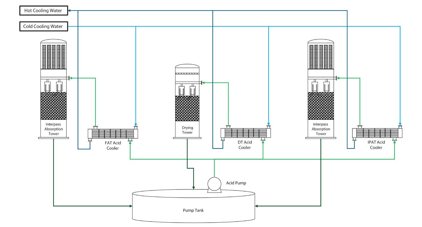
Sulfuric acid plants have various configuration possibilities for their acid circuit, often without considering energy recovery from sulfur trioxide absorption, as previously mentioned.
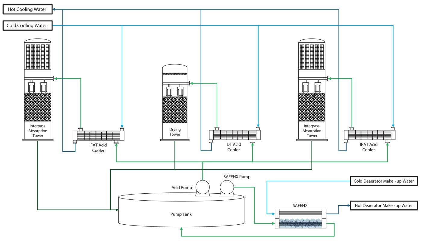
Figure 1 illustrates a very common double absorption plant configuration with a single pump tank and independent acid coolers. Essentially, the circuit includes an acid tank from which acid is pumped by a single vertical pump that feeds all acid coolers. These coolers use cooling water to adjust the flow temperature before feeding the towers. After the mass transfer occurred within each column, the streams return by gravity to the circulation tank.
When energy recovery systems are applied, they typically occur in absorption towers. For new plants, energy recovery can be integrated during the conceptual phase. However, existing plants require several modifications to adapt the interpass absorption tower for energy recovery. Figure 2 illustrates a possible configuration of a double absorption plant with a main single pump tank and energy recovery system, generating low-pressure steam.
In this configuration, sulfur trioxide is absorbed by hot acid in the lower deck of the absorption tower, which is oriented to the boot pump tank, from which a dedicated pump sends the flow to the SAFEHX, where the temperature is adjusted for proper feed at the top of the column lower deck. Cooling the hot acid partially evaporates the water stream fed into the heat exchanger, generating low-pressure steam, which is separated in the knockout drum. A fraction of the dedicated pump discharge sends acid to a crossflow heat exchanger, which cools heat recovery acid stream destined for the main pump tank while heating the acid stream from the main pump tank, optimising energy recovery and allowing acid concentration adjustment.
The absorption tower has an upper deck responsible for cooling the gas stream from the lower deck and absorbing any residual sulfur trioxide content. This process uses the acid exiting the drying tower, which passes through the upper deck of the absorption tower and returns by gravity to the main pump tank. Also note that part of the cooling water circuit is not necessary anymore, reducing cooling water consumption.
This configuration is one of many possible, depending on the final objective. However, the necessary modifications to convert a plant into an energy-recovering system can be observed by comparing Figure 1 and Figure 2. The main changes include:
n Replacing the absorption tower with a double-deck tower or adapting the existing one, if applicable.
n Adding a boot pump tank attached to the absorption tower.
n Adding the SAFEHX circuit with the exchanger and knockout drum.
n Adding a crossflow heat exchanger to minimise heat losses by crossflow acid streams.
n Adjusting the drying tower’s outlet stream to feed the top of the absorption tower’s upper deck, if applicable.
n Removing the cooling water circuit for the IPAT acid cooler.
n Adding a circulation pump for the hot acid circuit of the lower deck.
n Modifying applicable piping for system operation.
n Adapting or adding instruments and valves for proper system operation.
n Evaluating layout and interferences.
The economic and sustainable returns from adding an energy recovery circuit to an existing plant have both measurable and intangible aspects, making the configuration attractive. The primary benefits include steam generation or preheating higher-pressure water circuits, as well as reduced cooling water consumption. However, there are situations where plants cannot accommodate such significant modifications, whether due to financial, spatial, or temporal constraints. In these cases, simpler configurations are preferable.
Alternative heat recovery setup
The configuration presented in Figure 2 is essential when the goal is the direct generation of low-pressure steam, as hot acid circulation is necessary to reach boiling temperatures in water streams under pressures up to 10 bar. However, an enhanced balance of low-pressure steam does not necessarily have to come from direct steam generation but can also result from saving existing steam used in other applications.
The example presented in Figure 3 is the heating of demineralised water make-up streams to the plant’s deaerators. Deaerators are responsible for removing dissolved air from the demineralised water that supplies the plant’s steam circuits, including economisers, boilers, and superheaters. This process uses low-pressure steam at a sufficient flow rate to ensure the deaerators’ output stream has an appropriate residual dissolved air content with a temperature typically around 105°C. Depending on the plant’s steam circuit configuration and the amount of make-up water added to
Figure 3. Alternative heat recovery configuration.
Figure 4. SAFEHX sketch cross-sectional view.
the equipment, the steam consumption for sensible heat exchange can be significant.
A way to reduce steam consumption in the deaerator is by preheating the demineralised make-up water stream using heat from the acid circulation tank, as illustrated in Figure 3. In this case, it is not necessary for the acid to be at high temperatures, as all the water heating occurs through sensitive heat exchange. This makes the energy recovery circuit significantly simpler and an independent adjunct to the plant, allowing installation while the plant is operational, requiring only a simple shutdown for tie-in alignment. These changes are significantly simpler, cheaper, and quicker.
In the proposed configuration, if the existing pump cannot accommodate the required flow, a dedicated pump circulates the acid stream from the pump tank to the SAFEHX and back to the tank. This new pump requires a very low head since there is no need for elevation gains. Additionally, it cools the pump tank acid temperature, reducing heat duty on towers’ acid coolers, thereby lowering cooling water consumption.
For the water circuit, demineralised water is heated as much as possible before being fed into the deaerator. Due to a more favourable log mean temperature difference (LMTD), thanks to the water temperature conditions, the SAFEHX requires less heat exchange area than the configuration in Figure 2 for the same recovered heat duty. The demineralised make-up water heating translates into low-pressure steam savings in the deaerator.
This circuit is independent of the plant and can be turned on or off depending on the client’s needs and strategy. It also allows for installation while the plant is operational and can be installed in any suitable location.
To illustrate the recovery, a simulation was conducted for a plant with a capacity of 2450 tpd using the arrangement shown in Figure 3. A demineralised water flow of 100 m³/h is heated from 27°C to 70°C using heat from the pump tank. The recovered heat in the exchanger is approximately 5 MW, translating into savings of more than 8000 kg/h of low-pressure steam that would otherwise be used in the deaerators.
Without the recovery system, the tank would have an equilibrium temperature of 112°C, whereas, with the heat exchanger recirculation circuit, this temperature is reduced to 109.5°C, requiring less cooling water in each tower’s SAFEHX. For the same simulation, considering conservative evaporative losses of 1% in the cooling
tower, nearly 35 000 m³/year of process water make-up is saved.
The economic return depends on the steam cost on plant’s geographical region and the energy source for the saved steam generation, as well as the cost of water treatment for the cooling tower.
Operational safety
Energy recovery from sulfur trioxide absorption proves to be a highly attractive option both financially and sustainably, offering various possible application configurations depending on the client’s objectives. However, safety in this operation cannot be overlooked.
The historical record of this application is not favourable regarding safety risks, which is why Clark Solutions developed and patented the SAFEHX. This allows the previously overlooked possibility of acid energy recovery to become viable again, as the safety concerns have been effectively addressed.
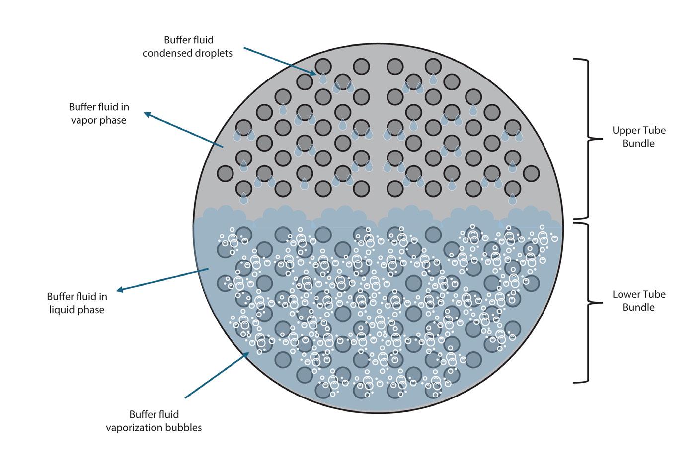
The heat exchanger consists of three zones (Figure 4):
n The lower tube bundle containing the hot fluid.
n The upper tube bundle containing the cold fluid.
n A closed shell containing the buffer fluid.
The operating conditions in the shell are maintained promoting the buffer fluid boiling with the hot bundle temperatures and condensating with the cold bundle temperatures. In this way, energy from the hot side is transferred to the cold side indirectly, through the buffer fluid latent heat in a cyclical approach.
This configuration offers two key benefits:
n In the event of a leak, the hot and cold fluids will not come into direct contact, as the selected buffer fluid is inert and immiscible to both and also has an intermediate density.
n The latent heat exchange of the buffer fluid allows for a highly uniform tube wall temperature.
These benefits can be leveraged for applications where fluids bring hazards when in contact (e.g., water and sulfuric acid), as well as for applications requiring tight temperature control to avoid thermal degradation (e.g., amine-based processes).
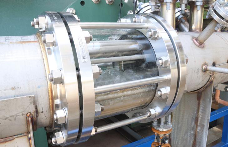
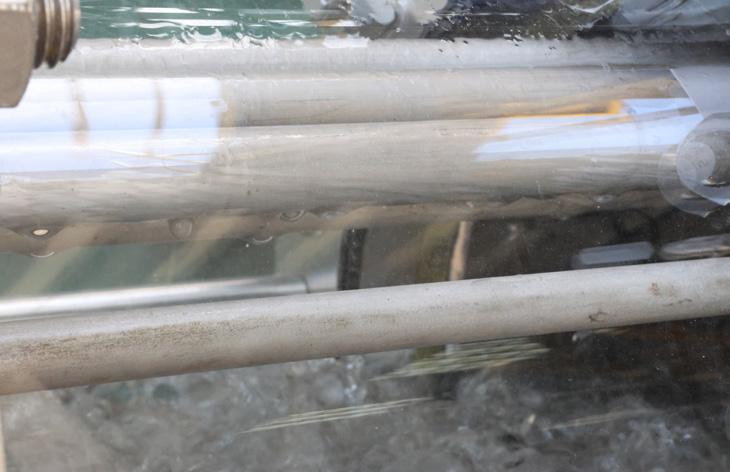
The SAFEHX concept and phenomena was already demonstrated and validated in a pilot scale unit at Clark Solutions’ R&D facility with results discussed in previous publications.
Conclusion
The SAFEHX technology proves to be a useful tool for enabling optimal energy efficiency and water consumption reduction in sulfuric acid plants. Its versatility allows for installation across a wide myriad of configurations, depending on the energy recovery objectives, specific application requirements, and client constraints, striving to balance sustainability, financial return, and safety.
Figure 5. Simultaneous boiling and condensation happening at each tube bundle.
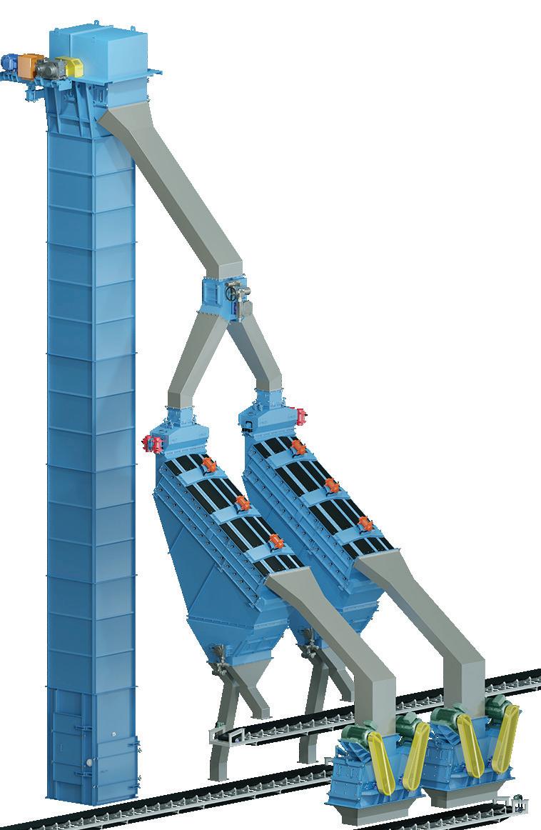
Hani Tello, ITT Rheinhütte Pumpen GmbH, Germany, considers important design features of pumps that convey hot sulfuric acid in high-temperature applications.
ulfuric acid is one of the most important basic chemicals in global industry. More than 200 million tpy are produced worldwide. However, production generates enormous amounts of CO2, polluting the environment and wasting valuable resources. Heat recovery systems (HRS) provide a solution by utilising the highly exothermic processes involved in sulfuric acid production. These systems can be integrated into sulfuric acid plants and adapted to the specific needs of the plant. The aim is to recover waste heat in the form of high and medium-pressure steam, which is used as process steam for internal processes or can be used to generate electricity. More than half of the world’s total energy is generated from heat. However, electricity generation from heat is usually based on the combustion of hydrocarbons, which causes high CO2 emissions. Since the heat in sulfuric acid plants is based on sulfur instead of hydrocarbons and is generated by the process anyway, the recovery of this waste heat is a carbon-neutral, and therefore environmentally friendly, way of generating energy.
What is HRS?
In a typical process cycle for sulfuric acid production, approximately 60% of the total energy is recovered as high-pressure steam, approximately 3% is discharged with the exhaust gas via the chimney, approximately 0.5% is lost as sensible heat in the product acid, and approximately 35 - 40% is available as weak heat in the acid cooler system.
The HRS is used to also utilise this weak heat, which is often released into the atmosphere or the cooling water system. This requires minor changes to the acid
cooling process (absorption and dry tower coolers). The HRS thus allows almost all of the waste heat to be used. This part of the process is modified so that the processes are operated at significantly higher temperatures, but the required SO3 absorption rates are still achieved and corrosion of the acid system is limited. Most of the SO3 contained in the process gas is absorbed, so the sulfuric acid concentration of 98.5 - 99.7% must be monitored and controlled. The absorption of SO3 and its reaction with the introduced water causes the acid temperature to rise to an elevated level. Heat is extracted from the acid and water is added in the next step to keep the acid concentration within the limits required for the process. The energy contained in the product acid is then recovered by heating water, which leads to the generation of additional steam and thus to a reduction in the total amount of steam required for consumption in the acid plant. The hot acid flows by gravity into a pump tank, from which it is pumped back into the HRS tower through the acid cooler. The remaining SO3 is then removed in the downstream intermediate absorption tower.
During the combustion (see numbers 2 and 3 in Figure 1) of sulfur to sulfur dioxide (SO2) and the conversion (see number 5 in Figure 1) of sulfur dioxide to sulfur trioxide (SO3), large amounts of heat are released, which are recovered as high-pressure steam. The subsequent processes are usually carried out at significantly lower temperatures in order to improve SO3 absorption and minimise corrosion in the plant’s acid system. However, due to the low temperature of the processes, the energy released is of little value, so it is typically discharged into a cooling circuit. This is where the HRS comes into play. This part of the process is modified so that the processes are operated at significantly higher temperatures, but the required SO3 absorption rates are still achieved and corrosion of the acid system is limited. Most of the SO3 contained in the process gas is absorbed, so the sulfuric acid concentration of 98.5 - 99.7% must be monitored and controlled. The absorption of SO3 and its reaction with the introduced water causes the acid temperature to rise to an elevated level. Heat is extracted from the acid and water is added in the next step to keep the acid concentration within the limits required for the process.
The energy contained in the product acid is then recovered by heating water, which leads to the generation of additional steam and thus to a reduction in the total amount of steam required for consumption in the acid plant. The hot acid flows by gravity into a pump tank, from which it is pumped back into the HRS tower through the acid cooler. The remaining SO3 is then removed in the downstream intermediate absorption tower.
The process itself is not new. The first applications were installed almost 40 years ago, but the issue of sustainability and reducing carbon emissions is now more relevant than ever. The system can be easily retrofitted into existing sulfuric acid plants. It is designed so that it can be shut down while the intermediate absorption tower remains fully operational. The plant can therefore be operated with or without HRS at any time. Depending on the plant configuration, additional production of low to medium pressure steam is possible. A large part of the ‘low-pressure’ heat generated in the absorption section of the acid plant is converted into valuable steam, while cooling water consumption is reduced by the same amount. When used in a newly planned plant in which the system is directly integrated, the system can be further optimised to generate the maximum possible amount of steam.
Pumps in HRS applications: hot, concentrated sulfuric acid
The challenge for pump manufacturers in this application lies in the high aggressiveness and extreme temperature of the acid, as well as the size and efficiency (> 80 - 85%) of the pumps. Sulfuric acid is one of the strongest acids. It is highly caustic and corrosive, which means that only a few pump materials can be used. Corrosion resistance in sulfuric acid depends mainly on the concentration and temperature. In HRS processes, ≈99.5% sulfuric acid is pumped at approximately 220°C, which places very high demands on the corrosion resistance of the material (see Figure 2).
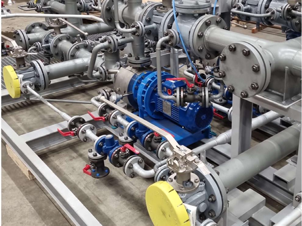
Only a few pump manufacturers offer pumps made of materials with the required corrosion resistance. In addition to the specific choice of materials, other design features are also important. A key factor is the sealing of the pump. For vertical HRS pumps, single-acting, gas-lubricated mechanical seals in cartridge design with a throttle on the tank side are the optimal choice. This reduces barrier gas consumption by creating a gas cushion to protect the seal and minimise the escape of the tank atmosphere. The gas also keeps unwanted atmospheric oxygen and/or humidity away from the gas seal. For vertical pumps used at lower temperatures, a gland packing can also be used as an alternative. In 2013, Rheinhütte Pumpen began working on HRS prototypes (see Figure 3) for a sulfuric acid plant belonging to a European fertilizer manufacturer. Existing pumps from another manufacturer were to be replaced. Vertical pumps were needed that could pump 99.5% sulfuric acid at 224°C. The GVRN pump was chosen, as it had already proven itself in sulfuric acid plants for decades. The only difference to previous projects was the extremely high temperature of the sulfuric acid. However, the special material previously
Figure 2. Character of sulfuric acid depending on the concentration.
Figure 1. Diagram of the sulfuric acid production process.
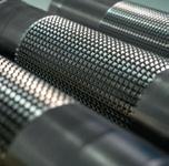
J&H EQUIPMENT INC.
The World Leader in Vibrating Wire Screens
Fertilizer Process & Recycle System
used in sulfuric acid proved to be resistant even at these temperatures. The existing material could therefore be used for the new application, but a few optimisations to the hydraulics and design were necessary.
Four of these pumps were delivered (see Figures 4 and 5) over a period of two years. The first three pumps were equipped with a double-acting mechanical seal. A single-acting, gas-lubricated mechanical seal was installed in the fourth pump. This design proved to be an equally suitable but more cost-effective solution.
Following the deployment of the HRS prototypes, a project was launched to implement further sizes for HRS applications in
order to cover future flow rates of up to 4000 m³/h and delivery heads of up to 30 m.
Further projects have been successfully completed. For example, since 2021, a Rheinhütte Pumpen HRS pump has been smoothly pumping 99 - 99.5% sulfuric acid at 220°C in a sulfuric acid plant in China.
In addition to the specific choice of materials, other design features are also crucial for this application. One important factor is the sealing of the pump. Single-acting, gas-lubricated mechanical seals in cartridge design with a throttle on the tank side are the optimal choice for vertical HRS pumps. The throttle reduces the consumption of the sealing gas by creating a gas cushion. This protects the seal and minimises the escape of the tank atmosphere. The gas also keeps unwanted atmospheric oxygen or moisture away from the gas seal. Alternatively, a stuffing box packing can be used in vertical pumps operating at lower temperatures. Both sealing variants were already proven sealing variants of the GVRN.
It was necessary to optimise the hydraulics and design in order to prevent crevice corrosion, for example. Due to the highly corrosive properties of the medium, screw connections were avoided wherever possible. Screw connections located in the medium are equipped with union nuts and additional O-rings. The flanges are cast onto the pipes instead of being connected with screw connections to prevent crevice corrosion. The pumps also feature a double spiral, which significantly reduces radial loads, resulting in less stress on the shaft and the roller and plain bearings. To minimise partial load recirculation (reduction of NPSHr), the suction covers have been equipped with vortex breakers.
To cover a wide performance range, the high-temperature version of this series has been developed in several sizes. Five sizes are already available, with more to be launched later in 2025.
Solution for a sustainable and carbon-neutral future
HRS applications enable sulfuric acid plants to achieve a positive energy balance. A sulfuric acid plant with a capacity of 3000 tpd can avoid up to 300 000 tpy of CO2 emissions by adding an HRS. When considering the annual production volume of sulfuric acid, it quickly becomes clear that this system can play a central role in the decarbonisation of this economic segment. In addition, plant operators benefit economically, as a large part of the energy required for the plant can be generated in-house and the investment usually pays for itself within a maximum of three years.
Until now, there has been only one pump supplier for HRS applications, which has effectively enjoyed a monopoly position, to the detriment of customers. Operators now have the option of choosing between two suppliers, both for existing and new systems.
Conclusion
HRS’s improve the energy efficiency of sulfuric acid plants and make a significant contribution to reducing CO2 emissions. Specialised pumps like the GVRN series are designed to reliably handle hot, concentrated sulfuric acid and withstand the demanding conditions of HRS applications. The technology is suitable for both new installations and retrofits, and the investment tends to pay off over time through energy savings. HRS thus plays an important role in supporting a more sustainable and carbon-neutral industry.
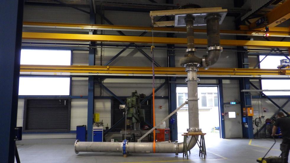
Figure 3. In 2013, Rheinhütte Pumpen installed the NPSH measurement setup of the prototype on the test bench.
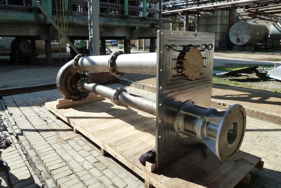
Figure 4. Delivery of the pump.
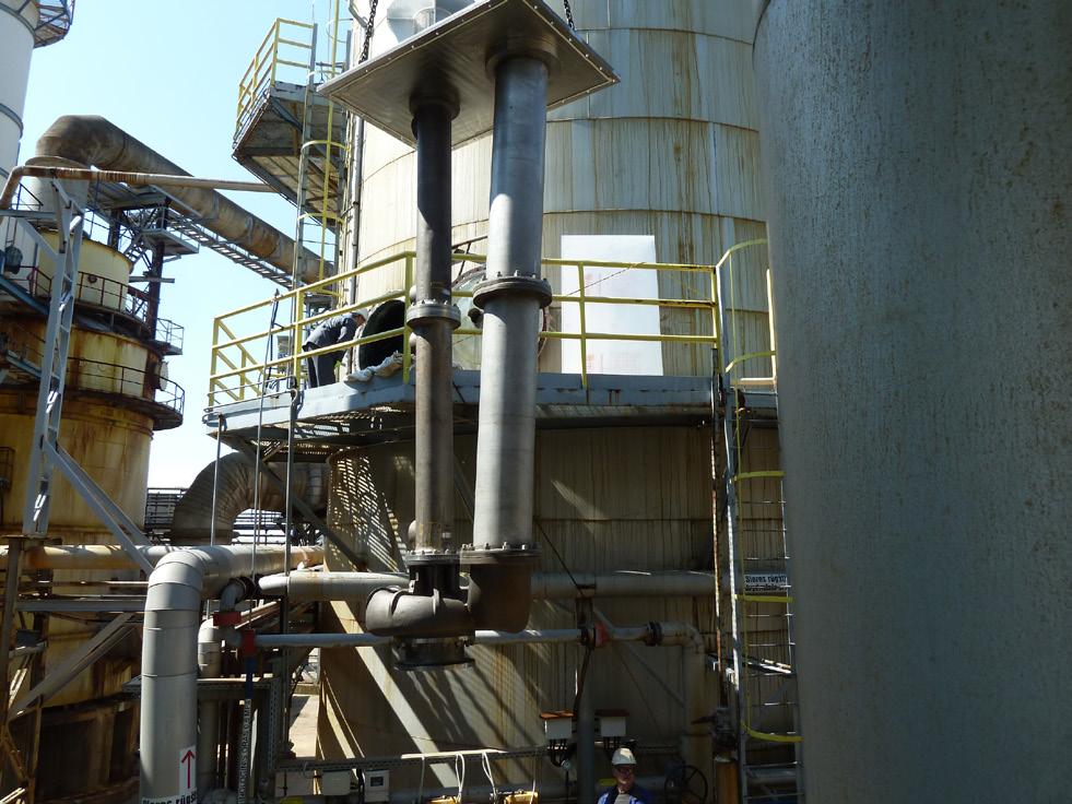
Figure 5. The pump, measuring 1.6 m x 1.2 m x 4 m, is carefully lifted into the plant.
Mastering molten
sulfur
Joseph Acevedo, CP Pumps Inc., explores heated, sealless pump solutions for handling molten sulfur.
odern sulfur production is dominated by recovery from sour gas, a hydrogen sulfide (H2S)-rich by-product of oil refining and natural gas processing via the Claus process. In this system, H2S is partially combusted to form sulfur dioxide (SO2), which then reacts with unburned H2S over a catalyst to produce elemental sulfur. Recovery efficiencies reach 94 - 97%, while advanced tail gas treatment units (TGTUs) can push recovery above 99.5%.1
Most of this sulfur is processed in sulfur recovery units (SRUs) and converted into sulfuric acid, often called the ‘king of chemicals’ for its central role in fertilizer production, metal refining, and chemical synthesis.2 Sulfuric acid is among the highest-volume industrial chemicals, with fertilizer production as its dominant end use.2,3 This underscores the need for safe, efficient pumping systems that can handle molten sulfur reliably. Roughly ⅔ of sulfuric acid is used to produce phosphoric acid for fertilizers,3,4 ensuring stable crop yields and food security worldwide. The remaining share drives many industries across the global economy: refining for steel, copper, and nickel; mineral processing for rare earths; and chemical feedstocks for polymers, detergents, and pharmaceuticals. Water treatment facilities also depend on sulfuric acid to keep municipal and industrial systems
health compliant. With production volumes measured in tens of millions of tonnes annually, downtime in SRUs can drastically affect plant profitability, as well as many dependent industries.
Forms and handling
Molten sulfur is supplied in two main forms: refined sulfur, requiring strict thermal control for high-purity uses such as pharmaceuticals and food-grade chemicals, and re-melted sulfur, produced from stored blocks and often subject to uneven melting and impurities.
Both pose risks of clogging and blockages if not carefully managed, necessitating pumps that can maintain stable
operation under variable conditions. Pump systems must not only be capable of moving sulfur efficiently, but also be tolerant of fluctuations in feedstock quality. Variations in viscosity, contamination levels, and thermal gradients can cause sudden failures in conventional sealed pumps.
Properties and operational considerations
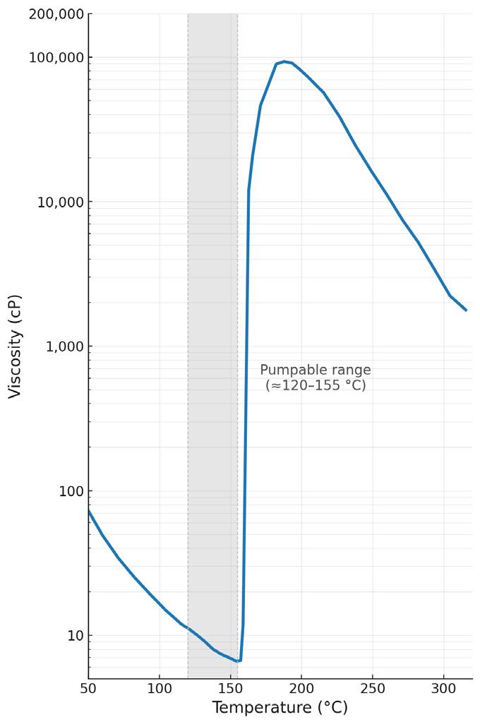
The operational demands of molten sulfur are driven by its physical and thermal properties. Its behaviour shifts rapidly outside a narrow temperature window, so effective handling depends on reliable heating and precise thermal balance, making molten sulfur uniquely challenging to manage:
n Density: ~1790 kg/m3 at 150°C, nearly twice that of water, requiring robust pump capacity and structural strength.
n Heat capacity: ~1.8 kJ/kg·K, less than half that of water, meaning sulfur heats more quickly under the same energy input.
n Viscosity: ~10 cP between 120 - 150°C, but rises by several orders of magnitude above ~159°C due to polymerisation (λ-transition or lambda-transition), making sulfur effectively unpumpable in that range.
n Solidification: below ~119°C, where sulfur crystallises, creating high risk of blockages and equipment failure.
NASA’s research demonstrated that minor temperature changes in molten sulfur can trigger polymerisation and upset flow stability.5 In practice, even a short dip below the liquid range can halt pumps and demand manual cleanout. Loss of containment in such events heightens the danger, introducing SO2 exposure and regulatory concerns. Uniformly heated, sealless pumps are designed to prevent these failures and sustain safe, continuous operation (see Figure 1).
Key features and benefits of heated, sealless pumps
CP has specialised in the design of heated, sealless pumps for demanding applications, such as molten sulfur handling. Some of the key features are:
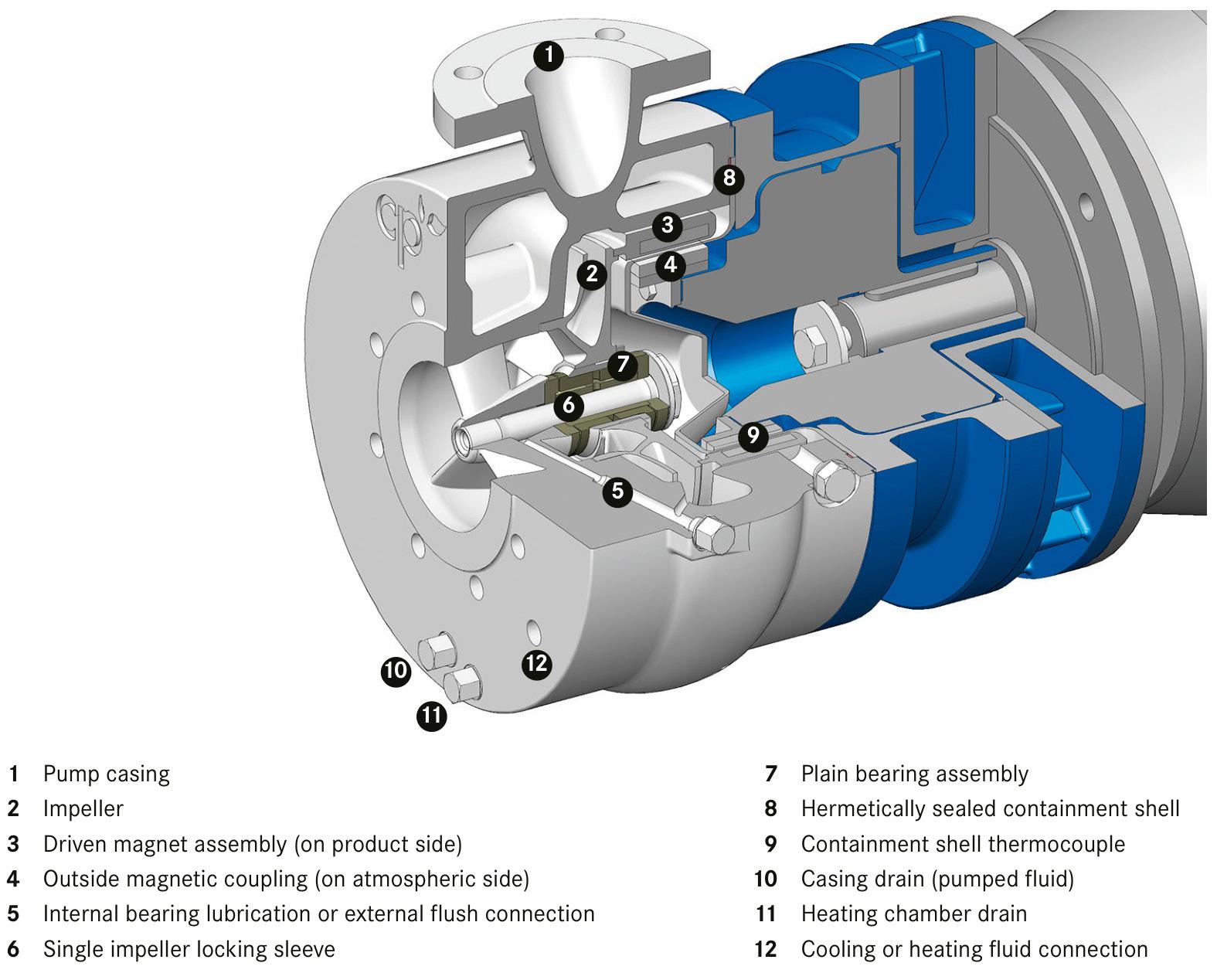
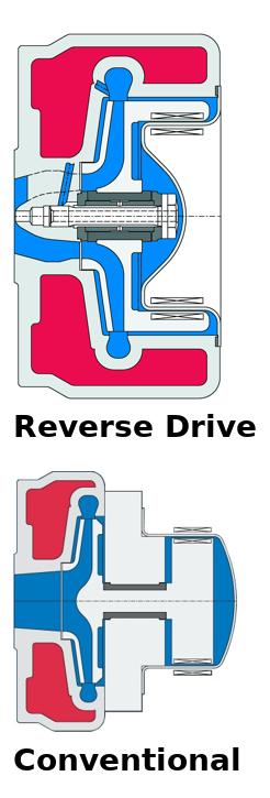
n Uniform heating: a single-piece, fully jacketed casing ensures stable thermal balance throughout operation, preventing cold spots that can cause crystallisation or blockages (see Figure 2 [Left]).
n Reverse drive design: the reverse drive design places the magnets inside the pump body, creating a compact geometry that allows for uniform heating across internal surfaces (see Figure 2 [Right]).
n Integrated monitoring: a shroud-mounted thermocouple measures directly at the hottest point of the pump (eddy-current peak). This real-time data enables operators to detect upset conditions such as an empty tank, closed discharge line, magnet slippage, or similar at an early stage and protects the pump from damage.
Figure 1. Molten sulfur viscosity curve (viscosity vs temperature). Data adapted from NASA (1982).
n WOC bearings: tungsten carbide-based WOC bearings combine toughness with thermal resilience, delivering superior resistance to torsional load, shock, and heat cycling – an essential balance for molten sulfur service.
n Hermetic sealing: no mechanical seals and leak-free containment of process media, ensuring safe, emission-free operation.
n High-temperature capability: samarium-cobalt magnets suitable for service up to 400°C.
n Regreasable bearings (MKTP): anti-friction rolling-element bearings designed for periodic relubrication, extending service life and reliability in demanding sulfur service.
Solutions for sulfur handling
Designed pumps should integrate directly into every stage of sulfur recovery and processing. Each series provides leak-free operation, thermal stability, and is ATEX compliant while being optimised for its role.
Liquid sulfur transfer: metallic pumps
In Claus process units, MKP pumps transfer sulfur at 130 - 150°C from condensers to storage tanks. Heated casings provide uniform temperature across the pump body, avoiding cold spots that cause solidification (see Figure 2 [Left]). With a magnetic coupling in place of mechanical seals, the pump provides hermetic containment and eliminates H2S leak paths. Covering flow rates from 3/h and heads up to 230 m, the MKP is well
Sulfur degassing: PFA-lined pumps
Before storage or shipment, molten sulfur must be degassed to remove dissolved H2S. MKPL pumps handle this duty with flows up to 350 m3/h and heads up to 80 m. The casing’s thick, vacuum-tight PFA lining is mechanically locked to a metallic shell, combining corrosion resistance with structural
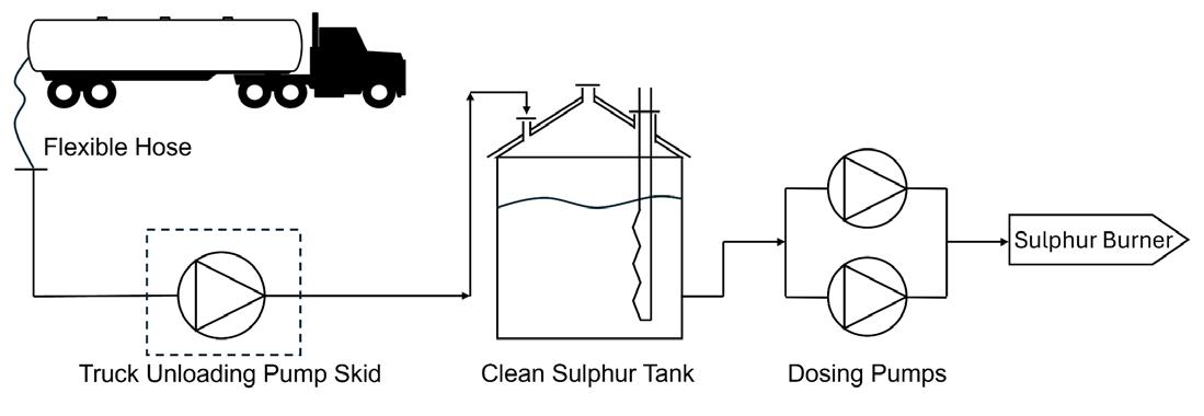
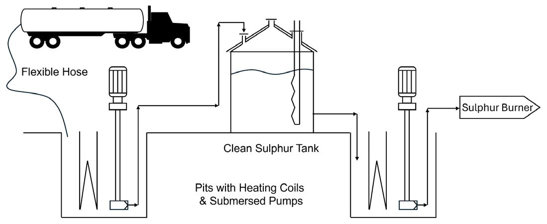
Figure 3. Sulphurnet process flow diagram – direct skid transfer.
Figure 4. Process flow diagram – legacy pit system.
Table 1. Vertical submerged sulfur pumps vs horizontal sulfur pumps
Vertical submerged sulfur pump
Horizontal sulfur pump
Accessibility Installed inside pit/tank → pump must be lifted out with cranes Accessible: easily accessible at ground level
Safety Hot sulfur, H2S exposure, open pit work → higher risk
Maintenance effort Complex: long shafts, bearings, alignment → time-consuming
Downtime Requires full pit/tank shutdown, heavy lifting equipment → costly
provides safe, reliable circulation in demanding degassing circuits.
Tail gas treatment: vertical metallic pumps
In compact TGTU systems, the MKTP pump provides circulation through scrubbers and heat exchangers where emissions compliance is non-negotiable. Its vertical column design allows installation in confined layouts while maintaining reliable performance. Regreasable anti-friction bearings extend service life under continuous sulfur duty and jacketed discharge pipes keep sulfur above solidification temperatures, while the sump-pump construction enables safe, reliable emptying of tanks without bottom drains. At flow rates up to 250 m3/h, heads to 100 m, and submersion lengths of up to 4 m, the MKTP is purpose-built for continuous service in tight spaces.
CP pump technology is highly adaptable beyond these core applications and is also applied in sulfur filtration, loading/unloading systems, and chemical feed circuits. The versatility of the designs allows for greater standardisation across site applications, thereby reducing spare part inventories and simplifying training.
Case study: truck unloading pump skids
Sulphurnet is a Dutch company based in Culemborg, the Netherlands, specialising in custom-made filtration solutions for industrial applications – with a strong focus on sulfur processing. They use heated, magnetically coupled, sealless MKPs across multiple modular skids for a leading oil and fuels producer, replacing legacy pit designs. Each skid features MKP pumps that unload molten sulfur from trucks into compact, jacketed clean tanks;
Safer: pump outside the pit, easier handling
Simpler: easier disassembly and reassembly
Quicker: can often be serviced or swapped with minimal interruption and standard tools
dosing pumps then provide a controlled feed to the sulfur burner (see Figure 3).
This approach eliminates pit systems (see Figure 4) and removes persistent burdens (round-the-clock steam coils, corroding covers, and hard-to-service submersibles), ultimately reducing maintenance costs and downtime (see Table 1).
The skid-installed, heat-jacketed MKPs deliver uniform casing temperature, hermetic reliability without dynamic seals, and built-in thermal monitoring at the pump’s hottest point. By eliminating large, corrosion-prone pits, the system tightens thermal control, delivering a safer handling experience. Operators can also expect faster recovery after outages, lower energy demand, and reduced maintenance exposure.
Sulphurnet has seen how design choices shape safety, efficiency, and life cycle costs. Legacy pit layouts impose heavy safety and life cycle costs, challenges addressed by the modular skids. Their prefabricated designs cut installation time, reduce on-site labour, and accelerate commissioning. Paired with heated, sealless MKPs, the modular systems deliver safer, more reliable, and more cost-effective sulfur handling (see Figure 5).
Conclusion
From SRUs to fertilizer plants, CP has supported operators worldwide with technology that improves efficiency, enhances safety, and extends asset life. Their application-driven designs combine advanced sealing, uniform heating, and real-time monitoring to deliver reliable performance across demanding applications. With proven engineering and life cycle support, they can help plants meet rising sulfur demand with confidence.
3. US Geological Survey (USGS). 2024. Sulfur [advance release]. In: 2019 Minerals Yearbook, Volume I – Metals and Minerals (S.A. Ash). US Geological Survey, Reston, VA. https://pubs.usgs.gov/myb/vol1/2019/ myb1-2019-sulfur.pdf
4. US Department of Energy (DOE) (n.d.). Energy and Environmental Profile of the U.S. Chemical Industry: Chapter 5 – Fertilizers. https:// www1.eere.energy.gov/manufacturing/resources/chemicals/pdfs/ profile_chap5.pdf
5. NASA (THEILIG, E.) (1982). A Primer on Sulfur for the Planetary Geologist. NASA CR-3594. https://ntrs.nasa.gov/api/ citations/19820025583/downloads/19820025583.pdf
6. JOHNSON, J.E. & HATCHER, N. (2003). Hazards of Molten Sulfur Storage and Handling. Laurance Reid Gas Conditioning Conference. https://www.ou.edu/content/dam/pacs/laurance-reid/documents/ resources-docs/7_hazards_of_molten_sulfur_storage_and_handling_ by_j_johnson_and_n_hatcher.pdf
Figure 5. Sulphurnet skid with an MKP metallic pump (transfer duty).
Larry Emch, IGS, USA, reviews the risks and mitigation strategies involved in reformer start-up during fertilizer production.
Steam methane reformers (SMRs), are essential to hydrogen production in ammonia and urea plants. These units drive highly endothermic reactions that support the synthesis of key nitrogen-based fertilizers. However, the start-up phase, especially following maintenance or turnarounds, presents elevated risks due to rapid and uneven thermal expansion, which can damage refractory linings, displace tubes, and impair heat transfer surfaces.
Such failures can compromise equipment integrity, as well as the continuity of the hydrogen supply, potentially disrupting downstream production. This article reviews common failure modes observed during heater start-up and highlights field-proven mitigation strategies that enable facilities to maintain throughput, preserve emissions compliance, and avoid unplanned downtime.
Common start-up issues in fired heaters
Despite rigorous procedures, primary reformers often experience avoidable issues during the post-shutdown ramp-up. These can be broadly categorised into mechanical failures, fouling and debris build-up, and thermal stress effects.
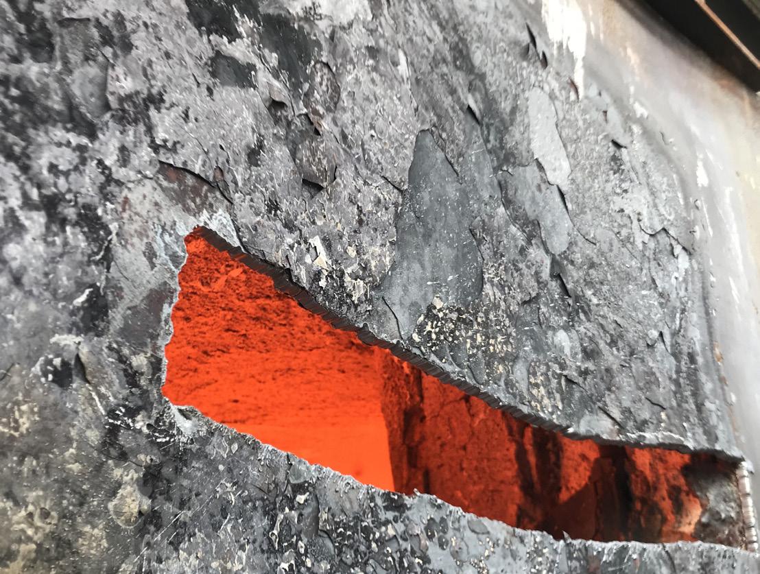
Refractory stress and thermal shock
Start-up conditions expose furnace linings to sudden temperature increases. In units with degraded anchors or hairline cracks, this can lead to spalling or collapse of refractory modules, introducing hotspots and structural instability.
In situ refractory reinforcement techniques, capable of being executed at operating temperatures, allow for localised stabilisation without necessitating a shutdown. These methods typically involve engineered anchors, baskets, and high-temperature backfill materials installed via live access ports.
Case study: primary reformer repair in ammonia production
At a major nitrogenous production site on the US Gulf Coast, an SMR plays a vital role in supporting year-round operations. With limited windows for shutdowns, this asset must remain online to meet aggressive production targets.
Over the last two years, the site has had three to four emergency interventions, specifically on this critical SMR unit. During the most recent event, the operations team identified damage in the refractory roof modules of the reformer cell. Left unresolved, this issue posed an immediate risk to structural integrity and production continuity.
Evaluating available options
The plant evaluated traditional refractory repair methods that would have required a full unit shutdown, including thermal cooldown, demolition, rebuild, and reheat, a multi-week disruption with high financial and operational cost.
Instead, the team opted for hot refractory repair solution.
Solution
delivery
A team was mobilised to perform a precision repair on the identified roof module areas, while the heater remained online. The scope included:
n Live removal of the affected outer shell to access the damaged refractory.
n Stabilisation of the remaining structure.
n Installation of engineered baskets and plates.
n Backfilling with refractory materials.
n Shell replacement.
The work was completed over three shifts, with all activities executed at full fire, avoiding heat-up or cool-down delays.
Quantifiable impact and results
This emergency intervention delivered mission-critical benefits:
n Prevented an unplanned shutdown of a high-throughput SMR.
n Maintained continuous production of essential fertilizers.
n Eliminated the need for an extended outage, saving hundreds of operational hours.
n Executed safely and efficiently, in alignment with site protocols and standards.
By restoring refractory integrity without disrupting load, the facility was able to meet production targets and uphold asset availability.
Figure 2. Online refractory repair.
Figure 1. Example of refractory failure.
The Only Choice for Modern Asset Integrity Management
Choosing the right asset integrity management software for your facility is a major decision. You need proven software that solves today’s challenges and supports long-term reliability. You need software that is integrated and built using decades of engineering expertise.
You need PlantManager SAGE®.
Developed with Equity Software’s long-term commitment to innovation and excellence, PlantManager SAGE is a complete collection of mechanical engineering tools to evaluate in-service equipment. Analyze and solve any industrial asset challenge with cloud-native software that is designed to perform, adapt, and excel.
Industry Leadership
Use FFS software in development for more than 30 years
Proven Accuracy
Make informed engineering decisions with precise results and calculations
Discover why the gold standard in FFS software is the trusted choice for asset management. Contact us for a detailed comparison.
Seamless Integration
Combine code calculations, piping analysis, hot taps, and flange optimization into FFS analysis
Built-in Compliance
Stay aligned with automatic updates to the latest codes and standards
Debris displacement and fouling in heat transfer sections
Maintenance procedures during shutdown sometimes result in residual dust and material debris left within the radiant section of heaters. As flue gases accelerate through the unit during start-up, this material becomes airborne, moving downstream into critical heat transfer surfaces such as the convection section and selective catalytic reduction (SCR) catalyst beds. The accumulation of fine particulates in these zones quickly undermines thermal performance and emissions control.
A solution to this issue is online convection cleaning methods which restore performance by removing in situ build-up from convection banks, eliminating the need for shutdown. It has proven effective in restoring process preheat and improving ramp-up efficiency.
In parallel, online vacuuming technologies target SCR units where catalyst surfaces are vulnerable to upstream debris. These services are particularly important in installations employing SCR for NOX compliance, as surface fouling directly impacts catalyst effectiveness. Online catalyst cleaning allows for removal of particulate material with no need to cool down the unit, maintaining both environmental compliance and operating efficiency.
Case study: increased catalyst performance without interrupting production
A fertilizer production facility operating in the western US identified performance limitations in its SCR system. Over time, airborne particulates had accumulated on the catalyst screens, increasing differential pressure and restricting airflow. Left unaddressed, this condition
Issue Root cause Impact Mitigation strategy
Refractory failure Thermal shock, degraded anchors Hot spots, structural instability In situ refractory stabilisation (live anchor and refractory repair)
Debris migration to SCRs Fouling moilisation during ramp-up
Increased dP, NO x control degradation Live catalyst vacuuming via access ports
Convection section fouling Settled debris from radiant section Reduced preheat efficiency In situ convection section cleaning
Undiagnosed hot spots or damage
Limited external visibility
Missed or delayed repairs
risked reducing process efficiency and forcing an unplanned shutdown.
The facility sought an in situ solution to reduce the SCR’s differential pressure while maintaining full online operation. Maintaining uptime was non-negotiable, and any intervention needed to avoid damage to sensitive catalyst components.
Evaluating available options
Rather than wait for a turnaround to perform manual or water-based cleaning, the site explored online maintenance options. The priority was to find a method that was effective, safe, and minimally invasive. After reviewing past outcomes with similar applications, the facility again selected an online vacuum service, an approach previously applied at this location with successful results.
The selection was based on this solution’s proven ability to deliver measurable pressure drop improvements without interrupting production or harming SCR internals.
Solution delivery
The technology was deployed to clean the catalyst screens from the exterior through existing access ports. The work was performed while the unit remained online, with no scope deviations or production disruptions.
This approach utilises lance-insertion technology to vacuum debris from catalyst surfaces with precision, all while preserving airflow integrity. In this case, a 9 ft 2 in. lance with a 15 in. tip was used to access and clean the screens. The effort restored visible clarity to the honeycomb openings, directly improving flow dynamics across the catalyst bed.
Quantifiable impact and proven results
The primary objective was to reduce the differential pressure across the SCR. Following execution, differential pressure dropped from 0.193 - 0.147, a significant improvement in airflow resistance. The entire project was completed in two days, without incident and with full client satisfaction, as noted in the completion certification.
By restoring optimal flow conditions, the cleaning operation not only enhanced process efficiency but also extended the service life of downstream equipment, such as the induced draft fan. No catalyst damage was reported, and the entire execution adhered to strict safety and quality protocols.
Visible signs like fallen refractory or shell hot spots often provide limited insight. Online inspection services such as Cetek Lancescope enable real-time internal diagnostics using high-resolution imagery up to 3000°F (1650°C), providing clarity and guidance for targeted repairs.
The furnace inspection system can be inserted into openings as small as 2.75 in. (7 cm) and reach up to 30 ft (9 m). In applications below 1000°F (540°C), the heater inspection system provides illumination via a high-temperature light source for optimal clarity.
Table 1. Common reformer start-up issues and mitigation strategies in fertilizer plants
This technology has proven decisive in complex cases where refractory and tube failures occurred simultaneously.
Case study: hot access creation and visual inspection to support reformer efficiency
At an ammonia production facility in Canada, the operations team sought clarity on suspected flow issues within their primary reformer’s SCR. Without definitive visibility inside the unit, it was difficult to determine whether fouling or debris were restricting airflow and impairing combustion efficiency.
Any exploration would need to be conducted carefully, with a priority on maintaining equipment integrity and safety under live conditions.
Evaluating available options
Rather than initiate a costly and disruptive shutdown, the site engaged a solution that allowed internal access and inspection while the system remained in operation. The goal was to use precision drilling and lance technology to examine the convection section and confirm, or rule out, the presence of blockages.
The team selected an online access creation service combined with online inspection technology to execute the task safely and without interrupting reformer performance.
Solution delivery
Three access points were created – one 4 in. hole and two 6 in. holes. Through these, lance-mounted cameras were inserted to inspect the face of the catalyst screens.
Figure 3. Before online cleaning.
While original plans included follow-up dry ice cleaning, this was ultimately not required as the inspection revealed no visible obstructions.
Manufacture r of Blending, Bagging and Transport equipment
35 Years of manufacturing excellence
From stand-alone machines to automated full factory solutions
EMT has proven for over 35 years to be the right partner for all your blending, bagging and handling machines in the fertilizer industry. Check our site today how we can assist you find the best solutions for your situation, scan the QR-code or go to www.emt.tech
High Speed Big Bagging line
• For big bags/Jumbo bags of 500 to 1250 kg
• Capacity 50 to 70 tons per hour
• Systems can be combined to an output of 120/180 tons per hour.
• Options include stainless steel construction or containerized units.
Stand Alone (Portable) Coating
•Capacities from 20 to 250 tons per hour
•Stand-alone or portable system
•50-250m3 per hour
•Automatic dosing process
•Options for built-in conditioner & liquid heating
• Continuous blending process
• Unlimited number of weighing hoppers
• Capacity from 20 to 300 tons per hour
• Fully automatic computer controlled mixing process Weighcont Blender
All procedures were carried out under negative pressure, and thermal conditions were closely monitored to ensure safe operations. Minor access modifications, including scaffold adjustments, were made to accommodate the core drilling scope.
Impact and results
The inspection verified that the convection section was operating without visible restrictions, giving the site assurance in the equipment’s performance. Importantly, the entire investigation was completed in two days, without any safety incidents or unplanned downtime.
Although cleaning was anticipated, the non-invasive inspection approach allowed the plant to validate internal conditions without committing resources to unnecessary maintenance.
Integration with reliability and maintenance strategy
Integrating these online services into reliability and maintenance strategies provides operators with effective options to manage start-up risks and improve operational flexibility. These services are particularly valuable for sites looking to extend run lengths between turnarounds or where unscheduled maintenance windows are limited.
By incorporating live heater maintenance capabilities, reliability teams gain access to field-proven solutions that mitigate degradation without disrupting process operations. This enhances the ability to sustain thermal performance, maintain emissions compliance, and preserve asset integrity across heater systems.
Table 1 summarises start up issues and mitigation strategies.
Field execution, safety protocols, and risk control measures
The delivery of in-service maintenance at elevated temperatures requires meticulous planning, specialised expertise, and strict adherence to safety protocols. These activities are typically carried out by qualified field technicians in collaboration with site health, safety, and environmental (HSE) teams, and operations personnel. Each job scope is developed based on comprehensive risk assessments and must align with the facility’s specific permitting and hazard control procedures.
Mobilisation can often be achieved rapidly through a global service infrastructure. Standard service packages encompass pre-job inspections, material procurement, on-site execution, and final reporting, ensuring full traceability and quality assurance throughout the process.
Engineering and operational risk controls
The execution of high-temperature maintenance on live process equipment presents unique technical challenges. To address these, industry best practices incorporate advanced technologies and engineered procedures, such as:
n Custom-designed tooling for controlled penetration of operational components.
n Water-cooled systems for thermal management.
n Welding techniques adapted for live, high-temperature environments.
Each project begins with a detailed engineering phase to define operational parameters and identify potential hazards. Risk mitigation strategies are then tailored to the specific equipment and process conditions involved.
Field crew qualifications
Personnel responsible for conducting online services must demonstrate experience in high-temperature applications. Required competencies typically include refractory installation, precision welding in thermally active zones, thermal imaging diagnostics, and the setup of controlled work access in high-risk environments.
Quality and safety management
Work should be performed under formal quality and safety management systems aligned with recognised international standards, including ISO 45001:2018 (Occupational Health and Safety) and ISO 9001:2015 (Quality Management). These systems ensure that procedures are consistently applied and safety performance is maintained across diverse geographical regions.
Summary
Fired heater reliability is critical for uninterrupted ammonia and urea production. Thermal stress, fouling, and mechanical misalignment during start-up pose recurring challenges. However, advances in live maintenance technologies allow these issues to be mitigated in situ, preserving productivity and minimising emissions impacts.
For operators in the fertilizer sector, such solutions represent a practical path towards more resilient, efficient, and compliant operations.
Figure 4. After online cleaning.
Charles Panzarella and Aaron Stenta, Equity Research, USA, assess how explainable AI can be used to solve problems with CUI in the fertilizer industry.
orrosion under insulation (CUI) is a big problem in the fertilizer industry – and in other industries as well. Perhaps one of the most well-known incidents is the Yara Ammonia plant explosion in 2009 that was caused by a CUI failure in an unused cold bypass line (the main line was kept warm enough that CUI was not a problem there).1 The insulation was damaged, and the coating quality was poor. This allowed water to make direct contact with bare metal, a necessary precursor for CUI. The plant was shut down for 12 months,
resulting in a production loss of 420 000 t of ammonia and 920 000 t of nitrate.
Not all CUI incidents are this catastrophic, many are just leaks, but even these can result in significant, undesirable economic, environmental, and health consequences that should be avoided as much as possible in an economically feasible way. The Oil & Gas Technology Centre (UK) estimates that CUI costs the global economy nearly US$5 trillion, and reports by global industry publications suggest that CUI accounts for more than 40% of a plant’s piping maintenance expenditure.2
The explainable AI solution
This incident could have been prevented if the more predictive explainable AI (XAI) model for CUI depicted in Figure 1 were available back then, since colder bypass lines like these are predicted to be at a higher risk of CUI. This model is more predictive, because it is fundamentally rooted in the causes of CUI as they are currently understood by physics and engineering. It also learns and gets smarter over time – a defining characteristic of intelligence – by directly integrating new observations into the model and blending them with the physics-based predictions and prior expert knowledge.
At the core of the XAI model are probabilistic, physics-based, causal networks, like the one shown in Figure 1 for CUI, that account for all known causes in a visual – as well as functional – way by connecting all contributing nodal factors with arrows in the direction of causality. Each node has one or more possible discrete states. The probability of each state is specified (or learned) for each possible combination of all its parent nodes’ states. The collection of all these conditional probabilities is known as the node’s conditional probability table (CPT). The probabilistic nature of this model is essential to properly capture all the inherent uncertainties of complex problems, such as CUI (measurement errors, probabilities of detection, uncertain damage
and failure time, uninspected regions, etc.), without being overly conservative.
Although it may seem subtle, the greatly enhanced predictive power of these networks comes from the information encoded within the many degrees of freedom provided by the network structure itself and of all its nodal CPTs. These networks mimic the way humans reach conclusions by integrating multiple sources of information – some of which may be missing, incomplete, uncertain, or even conflicting – the main reason why this approach is referred to as ‘explainable AI’. It is explainable due to the visual nature of the network, which allows one to see how and why any conclusion is reached, as opposed to traditional AI, which is a black box that reaches conclusions without explanations. XAI is more like a glass box.
Handling a problem as complex as CUI requires large networks that account for every possible contributing factor, but it all starts with the core network shown in Figure 1 that accounts for the direct causes of CUI. Moisture must first get in under the insulation and make direct contact with bare metal but only after the coating has degraded sufficiently. For water to get in, the jacketing must first fail. Even once water gets in, the amount of time that water makes direct contact with metal – the time of wetness – is also not known precisely, but this is a crucial factor that, along with the temperature-dependent corrosion rate, must be estimated as accurately as possible to reliably predict future metal loss.
Since none of these variables are known precisely, they are all treated as random variables described by probability distribution functions. Despite the uncertainty, as long as these are all accounted for in the right way, good predictions can still be made without being overly conservative. Even if nothing is known, predictions are still possible – they are just very uncertain. The key is that these networks work with perfect information or with no information and for every scenario in between.
Inspection data is incorporated to make the network smarter over time by adding additional green nodes (CUI-focused NDE inspection data), orange nodes (external API 570 inspection data), and purple nodes (live data streaming in from monitoring sensors). These nodes remain in the network while making future predictions (mimicking human memory), allowing the network to learn over time and get smarter from experience just like human experts do.
To predict risk, additional nodes are added to account for the failure thickness and consequence of failure, both of which are also permitted to be uncertain. Once risk is predicted, risk-informed decisions can be made in the same way as with traditional risk-based inspection (RBI) approaches, like that in API RP 581, but with improved probability of failure (POF) predictions. However, the true power of this approach goes beyond traditional RBI when it is fully implemented, by properly quantifying inspection effectiveness and accounting for all costs of inspection
Figure 1. The XAI model for CUI is more predictive than other models because it explicitly accounts for all known causes of CUI and because it incorporates all forms of inspection and sensor data to learn and get smarter over time.
and maintenance, and recommending even better decisions that meet some desired financial objective, such as maximising the return on investment.
There are numerous advantages to using these sorts of probabilistic, physics-based, causal networks to predict ageing asset damage and failure such as (also summarised in Figure 2):
n The visual nature of the networks makes them explainable –easier to understand and critically examine model assumptions so that improvements can be made over time.
n They are fully probabilistic, properly accounting for all sources of uncertainty in the inputs as well as the outputs (and for the uncertainty of imperfect inspections).
n Inputs can be missing or uncertain – for missing inputs, the model falls back to using the prior knowledge of a human expert or from previous data or experience. For uncertain inputs, values are specified using soft evidence (specifying multiple states with probabilities that add up to one).
n Human expert opinion is accounted for by setting prior probabilities or by adding additional nodes.
n An uncertain consequence is accounted for by entering soft evidence on failure cost nodes.
n Different sources of knowledge are blended together (physics-based models, expert opinion, real-world data, and observations from inspections and sensors) to come up with a single source of truth, as opposed to just picking one or the other as is the case with almost every other approach.
n The networks learn from experience and get smarter over
2. Some of the key advantages of XAI vs traditional AI.
n Complex models are built fairly easily, one node at a time, from the primary cause of the initial problem but also go on to expand and continuously improve over time as more is learned.
n Older rule-based models are given new life by converting them to networks, since all of the previously stated advantages can also be applied to these older models, which enhances their usefulness while still retaining their encoded historical knowledge (e.g., this has been done with the methods in API RP 583).
This new technology has resulted in Equity securing several patents.3,4
Sackett-Waconia Tower Blending systems are engineered ® technology, featuring dual NTEP-certified weigh hoppers and the high-speed HIM mixer, designed to simultaneously optimize rapid batch processing and pinpoint accuracy. This powerful combination ensures you can turn trucks faster than ever before, delivering perfectly blended product every single time.
Figure
Figure 3. The improved predictions of the XAI model for CUI save money by preventing leaks and focusing inspections.
Case study
As they say, the proof is in the pudding, and the proof here is the potential savings of US$38 million shown in Figure 3 that would have been realised for one early adopter of this XAI technology, had this method been implemented from the start (which it was not). These total savings are the result of having fewer failures (saving over US$20 million) and having more focused inspections (saving over US$18 million).
These savings are all made possible due to the nearly perfect predictions of metal loss by the XAI model, as shown by the parity plot in Figure 3 of predicted versus measured metal loss for all 42 locations where enough data was available to make these comparisons (no additional information gathering was required beyond what the client already had readily available). All of these points cluster very closely to the straight line of perfect prediction. All of this is achieved by having a more predictive model that accounts for the root causes of CUI in the proper way while also embracing uncertainty rather than ignoring it.
Beyond CUI
Even though the first focus of this approach is on CUI, similar approaches are being developed to improve the mechanical integrity of all assets across the board by building improved predictive models for every damage mechanism in API RP 571 that degrades the health of ageing assets (including internal as well as external corrosion). This addresses the two primary challenges for all mechanical integrity (MI) programmes which are: under investment leading to asset failure, and overinvestment resulting in unnecessary cost. These new XAI models – when extended to include decision and cost/benefit nodes – address both challenges by finding the optimal spend that perfectly balances the beneficial risk reduction of all inspection and maintenance activities with their cost to maximise return on investment. Operational decisions are also optimised, such as selecting the best feedstocks based on current market conditions or other considerations. This ultimately leads to better operational, inspection, and maintenance decisions over the entire life cycle of any ageing asset.
Next-generation RBI
The main purpose of these probabilistic, physics-based, causal networks, no matter how complex they may become, is to predict the failure time, and ultimately the risk, of any ageing asset as accurately as possible, since by knowing this, one can make the best risk-informed decisions regarding when to perform any activity related to inspection, and maintenance. That is why this approach, when fully implemented, is being billed as next-generation RBI. Not only that, but when all operational and process-related decisions are assessed, this leads to the full optimisation of all life cycle decisions. At the simplest level, these predictive XAI networks can serve as a drop-in replacement for the cruder POF models currently in API RP 581, while still allowing for the rest of that procedure to be followed, as is. However, the true power of this new XAI-based approach is only realised once these improved predictions are combined with enhanced knowledge of how inspection and maintenance activities quantitatively reduce risk vs their cost to recommend optimal decisions that maximise the total return on investment for any ageing asset.
2. TOMIC, B., ‘Interview: Cloud Solution Promises to Drive Down CUI Maintenance Costs in O&G Industry’, OEdigital, (2021), https://www. oedigital.com/news/485753-interview-cloud-solution-promises-to-drivedown-cui-maintenance-costs-in-o-g-industry#:~:text=The%20cost%20 of%20CUI%20is,on%20CUI%20we%20have%20incidents
3. P E2G CorrSolutions, LLC. (2022). “Failure Prediction and Analysis Techniques.” U.S. Patent 11,262,196, filed April 11, 2019, and issued (March 1), 2022.
4. PANZARELLA, C., STENTA, A., OSAGE, D. (2025). “Asset Lifecycle Optimization Systems and Methods.” US Patent Application Number 19/033,030, filed 21 January, 2025, pending.
Paul Smith, Legacy Building Solutions, USA, explains how tension fabric buildings can offer excellent resistance to fertilizer’s corrosive attacks.
Corrosion can be a killer for fertilizer distribution facilities if they are not built to protect themselves against the caustic nature of the materials they are housing. Everybody in the fertilizer business understands this, but not all may be aware of the industry options that exist to provide optimal corrosion protection for a building.
When it comes to fertilizer storage structures, some basic truths are that a metal building would be eaten alive, and that wooden structures can get very expensive as their desired square footage grows. The secret has been out for decades that cladding a large structure with fabric is an economical choice – and one that significantly helps combat corrosion concerns, as the polyvinyl chloride (PVC) fabric material used is naturally resistant to corrosive elements.
That said, even tension fabric buildings have historically had their own vulnerabilities, since the framing structure is still made of metal. Over the past several years, however, leading fabric building manufacturers have developed a number of new innovations in hopes of fully solving the corrosion problem for those handling fertilizer.
Solid solutions
Older style fabric structures typically used hollow-tube truss frames. Even if the exterior surfaces of these trusses were treated to help prevent corrosion, a common problem was that corrosion
could originate inside the tube and rust the frame from the inside out, causing irreversible damage over time that was not even visible until it was far too late.
A major shift occurred when industry leaders developed a patented method for attaching tension fabric panels to a structural steel frame. With solid I-beams replacing hollow tubes, one major weak point was addressed, but more work was left to be done.
Beefing up the barrier
For applications such as commodity and fertilizer storage, as well as environments with high moisture content, fabric building manufacturers initially utilised hot dip galvanising to protect the structural I-beams against corrosion.
Galvanising adds a thin, 3.9 mil layer of zinc around the steel by immersing the entire steel beam into a molten zinc bath. The intention of that layer is essentially for it to be sacrificed over the course of several years, with corrosion gradually eating the zinc away, rather than directly attacking the steel beneath. In effect, galvanising slows down the corrosion process as much as it can. Eventually, however, that protection will degrade and leave the I-beams vulnerable.
To provide more permanent protection against corrosion and increase facility longevity, manufacturers considered the use of epoxy coating. Unlike galvanising, where the protection disappears
over time, epoxy creates a true barrier between corrosive elements and the steel framing members. While epoxy would undoubtedly provide an upgrade, it was frequently considered cost-prohibitive due to the outsourcing involved in producing and shipping the coated steel.
Figure 1. The strength of structural steel framing allows engineers to design large fabric buildings with long clear spans, providing ample floor space for fertilizer storage, mixing, and loading.
Figure 2. Using epoxy coating on structural steel I-beams creates a protective barrier, extending the life of a building in a corrosive environment.
Figure 3. Results of a 2000-hour salt fog test. A galvanised steel beam was fully corroded, while an epoxy-coated steel beam only rusted where it was intentionally etched into for testing purposes.
Taking matters into their own hands, some suppliers – such as Legacy Building Solutions – invested in adding to their on-site production facilities to include in-house steel beam fabrication and painting. Not only did this bring down the cost of offering epoxy-painted I-beams, but it also gave these companies an opportunity to improve upon and fully control the quality of their product.
Steel treatment
The epoxy treatment process begins by sandblasting the I-beam in a controlled environment to create a consistent blast profile on every inch of the steel. For the highest level of corrosion protection, the steel gets a commercial blast to remove any impurities or defects and fully clean the steel surface.
Without this blast process, the steel could be susceptible to a filiform type of corrosion that can develop underneath the protective coatings. This is a key difference from hot dip galvanising, which involves no blast – instead, the steel is usually just wiped down and then dipped, meaning that any blemishes or potential contaminants are not being taken care of prior to being coated.
The next step after blasting is adding a 3 mil layer of zinc that is applied with a paint method rather than dipping. In effect, this first paint layer offers protection that is similar to the final product with hot dip galvanising. Two separate 5 mil coats of epoxy are then layered over the zinc paint. The end result is a fully protective 13 mil barrier that prevents fertilizer’s corrosive dust from ever contacting the steel.
Corrosion testing
To determine the level of corrosion protection provided to a steel beam by epoxy coating, in comparison to hot dip galvanising, manufacturers have put these methods through salt fog tests developed by the American Society for Testing and Materials (ASTM). Where some corrosion tests will try to emulate typical working conditions, the 2000-hour salt fog test introduces constant and aggressive salt fog to materials that are expected to face the most corrosive applications, such as fertilizer storage.
In one such 2000-hour test, a hot dip galvanised steel beam and epoxy-coated steel beam were both placed in the same closed and controlled environment. The galvanised steel came out fully corroded and rusted over. The epoxy-coated steel was clear of corrosion, outside of a thin line that was intentionally etched beforehand to see if the coating would help prevent rust from spreading into the rest of the piece; even in that purposely damaged area, the corrosion did not penetrate below the epoxy coating.
Structural benefits
When one understands how big of a game changer it was for tension fabric buildings to incorporate rigid-frame, structural I-beam engineering, it is even easier to see why the suppliers who offer it go to painstaking lengths to protect those steel beams from corrosion.
Rigid frame design brought a universally accepted engineering practice to fabric structures, which had lacked consistency and quality with web truss framing. The new approach also provided the ability to completely customise a fabric building with the exact dimensions desired and other unique features.
For fertilizer storage, fabric-clad facilities can be built with large square footages at a much smaller cost than comparable wood buildings. Engineered steel I-beams deliver excellent structural strength, which allows for long clear span designs that provide more wide-open floor space for mixing, arrangement of material piles, and for load-in and load-out equipment to operate.
Because the rigid frame design process always starts with a clean sheet, the manufacturer and customer can work together from the beginning to optimise the project for the user’s specific needs. If the facility requires an overhead conveyor or other collateral loads that must be supported by the structural frame, engineers simply account for the loads in the design software to provide optimal I-beam depths and thicknesses precisely where required.
Another advantage for fertilizer storage is the relative ease with which a fabric building can be ventilated to stay dry. Standard building designs can incorporate low-cost passive systems utilising ridge and soffit vents that rely on the natural movement of warm air, and this is often all that is needed to address ventilation concerns from moisture and humidity. For cases where fans or other supplemental ventilation may be needed, those mechanical items can be implemented to hang from the steel frame.
Ideal cladding
One area where corrosion is not a factor is with the fabric cladding material itself. Whether using PVC or polyethylene (PE), architectural fabrics are not susceptible to corroding, making them a popular choice for fertilizer structures. Fabric has long been known to provide a variety of operational benefits as well. Its translucency allows for natural daylighting inside a building. Unlike metal sheeting, fabric has thermally non-conductive properties, helping to keep building interiors warmer in the winter and cooler in the summer.
Fabric’s benefits can be enjoyed for many years, but the type of fabric used can have a big impact on the building’s overall longevity. In the past, PVC was commonly reserved for higher end projects due to its price point. However, leading suppliers have helped bring a high-quality PVC to market at a similar cost to PE.
This advanced PVC features a high-strength woven fabric with additional primer and lacquer layers to provide more durability. In fact, it is designed to retain more than double the tensile strength of a standard PE fabric, which subsequently provides the building with a much longer life expectancy.
Winning the war
Solid framing materials, superior coatings, and better fabric technology have combined to help tension fabric buildings push back against corrosion in a major way. Through custom engineering and applying the proper protective measures, these structures provide a cost-effective and long-term solution for fertilizer facility operators.
Case study: Paul Meyer Chemicals
Paul Meyer Chemicals was established in the 1980s in Walcott, Iowa, US, and provides Midwest farmers with chemicals, fertilizer, and seed. Due to increased consumer demand and years of continued growth, the company needed a new bulk fertilizer storage building.
Decarbonizing
the
sulphur industry with GEA
Decarbonizing the sulphur industry with GEA
Remain competitive and compliant in a world that rapidly moves toward net-zero emissions with our:
Remain competitive and compliant in a world that rapidly moves toward net-zero emissions with our:
•Advanced gas cleaning GEA gas treatment solutions that remove harmful substances like SOx, NOx & particulate matter.
•Advanced gas cleaning GEA gas treatment solutions that remove harmful substances like SOx, NOx & particulate matter.
•Energy recovery and efficiency systems that recover and reuse excess heat from industrial processes —lowering operational costs and your carbon footprint.
•Energy recovery and efficiency systems that recover and reuse heat from industrial processes —lowering operational costs and your carbon footprint.
•Our end-to-end Carbon Capture solutions. From gas pre-treatment to CO2 capture, conditioning, liquefaction or conversion into CO2-based products.
•Our end-to-end Carbon Capture solutions. From gas pre-treatment to CO2 capture, conditioning, liquefaction or conversion into CO2-based products.
Figure 4. Needing more fertilizer storage capacity, Paul Meyer Chemicals had a new tension fabric building custom-designed for their operation.
Figure 5. The natural corrosion-resistance of PVC makes an optimal cladding material for fertilizer facilities, and the fabric’s translucency provides a brighter working environment.
The construction timeline was a critical factor. Knowing that spring planting season is the most crucial for local farmers, the goal was to have the building project completed within a few months, in order to be up and running for the spring.
When researching potential building partners through their agricultural network, the company began to consider a fabric building. They specifically focused on Legacy Building Solutions, a manufacturer that had provided tension fabric structures for several other fertilizer suppliers in the state. The ability to custom design the building and engineer it around their existing new equipment was a key consideration in deciding what company to use, in addition to being able to meet the construction timeline.
The facility features a structural I-beam frame. Since Paul Meyer Chemicals works heavily with fertilizer, corrosion protection for the steel beams was essential to ensure longevity for the building. Fertilizer corrodes nearly everything it touches, prompting the company to choose a high-level epoxy coating to protect against corrosion.
The building’s roof and sidewalls feature high-strength PVC cladding. The white fabric roof offers 12% translucency, allowing plenty of natural sunlight to filter in and provide a brighter daytime working environment and reduced lighting costs.
The completed building measures 84 ft wide and 120 ft long, for a total area of 10 080 ft2, enough for a material storage capacity of 1700 t. It is designed to withstand wind speeds up to 105 mph and 30 psf ground snow load. The building frames were also engineered to support a 550 lbs/ft drag conveyor system.
A podcast series for professionals in the downstream refining, petrochemical, and gas processing industries
EPISODE 11
Graham Faiz, Head of Digital Energy, DNV, explores the current state of digitalisation in the energy sector and the key drivers behind digital transformation. Graham considers how companies can move from pilot projects to full-scale deployment of AI and digital tools.
EPISODE 12
Omar Sayeed, Centre of Excellence Leader for Reliability, and Rahul Negi, Director of AI and Industrial Autonomous, Honeywell Process Solutions, consider how new, innovative technology can help to overcome some of the challenges facing the downstream oil and gas sector.
EPISODE 13
Sarah Miller, President and CEO of the GPA Midstream Association and CEO of the GPSA, outlines the vital importance of midstream operations, and some of the key challenges and opportunities facing the sector.
EPISODE 14
Rob Benedict, Vice President, Petrochemicals and Midstream, American Fuel & Petrochemical Manufacturers (AFPM), discusses the outcomes of the final round of UN negotiations for a Global Plastics Treaty.
EPISODE 15
David Wilson, CEO, Energy Exemplar, considers the role that oil and gas is currently playing in the booming data centre industry, and what the future holds.
Listen and subscribe here
The heart of the matter
Leslie David, Conveyor Belt Specialist, details how deficiencies in the carcass of a conveyor belt can significantly reduce both performance and longevity.
Rubber belts with a ‘multi-ply’ synthetic textile reinforced inner carcass are the most commonly used type of conveyor belt. Its inner carcass serves as the belt’s core structural element and provides the inherent characteristics of every conveyor belt,
such as its tensile strength and elongation (elasticity or ‘stretch’ under tension). Its primary function is to transmit the tension required to lift and move the loaded belt, while also absorbing the impact energy generated as material is loaded onto the belt.
Perhaps because the thick outer covering of rubber makes the carcass invisible to the eye is why rubber covers, rather than the carcass, are widely considered to have the biggest bearing on operational performance and longevity. Whatever the reason, the fact remains that the carcass is the heart of every conveyor belt. Its importance should never be underestimated because deficiencies can be extremely costly.
Fabric quality
Almost without exception, rubber multi-ply belts use synthetic fabrics. Currently, the most commonly used type is a combination of polyester and nylon (polyamide), referred to as ‘EP’. Even in belts that have low quality (low cost) fabrics, it is unusual to find a fabric that has inadequate tensile strength. However, although the amount of material used in the longitudinal strands of the fabric may be sufficient to achieve the required tensile strength, to reduce cost, the use of the more costly nylon transversal weft material is kept to a minimum. As a consequence, rip and tear resistance is reduced and elongation (stretch) is low, which can cause problems with transition distances and a general inability to accommodate the contours of the conveyor and its drums and pulleys. Ultimately, this can lead to the premature failure of the belt.
A common deception
Unfortunately, due to price competition, it is becoming increasingly common for some manufacturers, traders, and importers to supply belts that have entirely polyester (EE) fabric plies in a carcass that is declared to be an EP construction. The reason for this is that EE fabric costs 30% less than EP fabric. This is significant because, after rubber, fabric is the highest cost component, so using cheaper polyester fabric is a big help towards achieving the perception of a lower ‘like for like’ price. The basis of using a mix of polyester and nylon fabric is that it has the best balance of mechanical properties allowing a conveyor belt to
Figure 1. Out of sight, out of mind. Looks fine on the outside, but what is happening inside?
Figure 2. Not what they seem – some belts are supplied EE fabric plies in a carcass declared as being an EP carcass.
Figure 3. There can be enormous differences in the strength and quality of the fabric, and a corresponding difference in their cost.
run straight, to trough, to flex round pulleys and drums, stretch, provide transversal rigidity, longitudinal strength, and much more besides. Unless the weave pattern has been specifically designed and manufactured, the use of EE fabric compromises a number of essential mechanical properties. The biggest danger is that in a conventional weave, a polyester weft can cause low transverse elasticity, which reduces troughability, impact resistance, and also causes tracking issues.
It is important to note that the use of EE fabrics does play an important role in certain applications (sawmill belts for example) and special constructions, such as the fabrics used by Fenner Dunlop in Europe and North America to produce its high performance single and dual-ply X Series range. However, under no circumstances should a belt be supplied that contains EE fabric that has been specified as being an EP construction.
There can be enormous differences in the strength and quality of the actual fabric and a corresponding difference in their cost. Yet again, this is almost entirely influenced by whether the belt manufacturer is at the ‘quality end’ of the market or the ‘cut-throat’ end. Although they may be the same specification on paper,
the loadbearing strength both longitudinally and transversely can be inconsistent and prone to steering and handling problems.
There are also different grades of fabric that can be used. For example, Nylon 6 and Nylon 66 are most commonly used for conveyor belt fabrics. The primary difference between them lies in their chemical structure, with Nylon 66 being generally stronger, stiffer, and more
Sulphur at the perfect temperature
CP’s heating-jacketed, sealless magnetic drive pumps ensure that your molten sulphur remains in the best pumping condition.
Figure 4. Delamination – layers separate and the belt literally falls apart.
heat resistant whereas Nylon 6 is slightly softer and more flexible, making it better for applications requiring a higher level of impact resistance and better elastic recovery.
The differences can be considerable. For example, Nylon 66 fibres are 33% more resistant to abrasion compared to Nylon 6, withstanding up to 60 000 cycles compared to 40 000, and is often used in high-performance industrial components. Both grades have their place, depending on the belt specification and intended use. The most important point is that those manufacturers searching for the most economical solution will use the lowest cost option regardless of its suitability.
Carcass failure caused by delamination
The term ‘adhesion’ relates to the adhesive bond between the inner ply layers to adjoining layers, and between the surfaces of the outer plies and the rubber covers. It is defined as the force required to separate
adjoining plies and/or between the plies and the outer covers. The adhesion properties of a belt are fundamental to its durability, functionality, and structural integrity. It determines a belt’s ability to trough and carry heavy loads without the risk of ply separation. Conveyor belts continually flex over pulleys and drums, which creates stress. It is therefore essential that the belt has adequate ply adhesion to withstand this stress without delaminating, which is where the various layers separate, and the belt literally falls apart.
Adhesion also has an enormous impact on the reliability of splice joints because insufficient adhesion compromises the strength and longevity of the joint. Unsurprisingly, the root cause is the use of low-grade raw materials such as polymers, crucial fillers such as carbon black, vulcanising agents, plasticisers, resins, and curatives. Other causes include overheating or overcooking during the vulcanisation process and the use of cheap bulking fillers such as chalk or clay.
Elongation: stretching the limits
Elongation is an often misunderstood technical term applied to rubber conveyor belts. It is best defined as the change in length (stretch) of a belt when subjected to tensile stress of which there are three forms – elastic elongation, permanent elongation, and elongation at break. With each tensile stress below break load, the belt is subject to an elongation which, when the stress is relieved, partly recovers (elastic elongation) and partly remains (permanent elongation). The elongation at break is the amount of elongation at the moment the belt breaks. All three forms are effectively determined by the properties engineered into the belt during its manufacture.
The elongation of a carcass is critical in determining how a belt will react when subjected to varying stress levels. These stresses change due to system influences such as tension, transitions, vertical and horizontal curves, turnovers, and crowned pulleys. Insufficient elongation is mostly an issue in areas where a multi-ply belt needs to stretch, such as troughing and bending round pulleys for example. It can cause localised tension build-up, which can have an especially negative effect on the splice joint. It can also lead to shear stresses that may in turn cause delamination (ply separation) issues. Conversely, too much elongation can result in insufficient tension, which can lead to premature wear and tear.
Conclusion
As has been explained, the quality of the carcass is of equal importance to the quality of the rubber covers. They are inter-dependant and in both cases, when a low selling price is the driver rather than reliability and longevity, conveyor productivity suffers and running costs escalate. That really is the heart of the matter.
Figure 5. Elongation at break is the amount of elongation at the moment the belt breaks.
Argus Clean Ammonia Europe Conference
2-4 December 2025 | Rotterdam, Netherlands
Bringing together industry pioneers driving clean ammonia adoption in Europe
as a group and save up to 20%
New for 2025: Enhance your conference experience and maximise your investment by attending our exclusive add-ons
Tuesday, 2 December
Regulation & Trade Dynamics Workshop
Explore the evolving European regulatory landscape for hydrogen and ammonia in this expert-led workshop. Gain essential insights to stay compliant, uncover new opportunities, and engage directly with policymakers through focused analysis and strategic discussions.
Host sponsor: Platinum sponsor:
Gold sponsors:
Thursday, 4 December
Portlantis site visit with Port of Rotterdam
Maximise your networking time and gain a unique perspective on the future of clean ammonia infrastructure at Europe’s largest port. Discover the ports impact on industrial innovation, environmental sustainability, and economic growth during a guided tour.
Subhashis Ghosh, Metso, analyses strategies that can be used to optimise fertilizer mining and processing.
ertilizers have become a cornerstone of global food security. Since the 1960s, their increased usage has enabled modern agriculture to meet the nutritional demands of a rapidly growing population. Despite projections indicating a slowdown in population growth over the coming decades, the world is still projected to surpass 9 billion people by 2050, driving continued demand for efficient fertilizer production. This demand exists alongside new challenges. The fertilizer manufacturing industry now faces evolving sustainability requirements, stricter regulations, fluctuating raw material costs, and shifting market dynamics. Meeting these challenges requires reliable, energy-efficient processes and technologies that enhance productivity whilst minimising impact.
From mine to market: the growing demand for phosphoric acid and potash
The three essential macronutrients in fertilizers are nitrogen, phosphorus, and potassium. While nitrogen is derived from air and does not require mining, phosphorus and potassium come from mineral deposits and require extraction and processing.
Phosphate rock, a primary source of phosphorus, is typically mined using open-pit methods. Potash, which provides potassium, is extracted from deep-shaft mines or, at times, strip mines.
Global demand for phosphoric acid and potash continues to grow steadily. According to industry forecasts, global phosphoric acid supply capacity is expected to grow at approximately 4.2% annually from 2025 through the early 2030s, while demand is also projected to increase at around 4.2% per year.
Similarly, potash demand for agricultural applications is projected to increase approximately 4.5 - 5.3% per year. There are two common forms of potash – muriate of potash (MOP) and sulfate of potash (SOP). Unlike MOP, SOP is free of chloride, which is harmful to plants. As a result, SOP commands a premium price of approximately 50% as it is used primarily on high-value crops, such as leafy plants, fruits, and vegetables.
Integrated solutions
From ore extraction and beneficiation, to granulation and waste management, fertilizer production involves multiple stages, each of which presents opportunities for efficiency gains and sustainability improvements. Metso supports fertilizer producers through an integrated portfolio of equipment, plant, automation, and life cycle services across the entire processing flowsheet, including mining, comminution, beneficiation, filtration and tailings management.
Mining and comminution
The exploration and extraction of phosphate and potash ores are the first critical steps in fertilizer manufacturing. It is important for operations to achieve the required particle size for downstream processing, thus high throughput and energy efficiency are essential for maintaining competitiveness.
Metso’s portfolio includes the MP TM cone crushers and HRC TM high-pressure grinding rolls, which are capable of in delivering high throughput whilst maximising crushing performance at the lowest possible cost per ton. These technologies can help operators in reducing their energy consumption and improve downstream process performance, enabling better recovery in beneficiation.
To further optimise operations, Metso’s Process Optimisation (PRO) services provide consulting, laboratory analysis, and advanced digital tools for process improvement.
Beneficiation and filtration
Once the ore is reduced in size during comminution steps, phosphate and potash ores undergo beneficiation to separate valuable minerals from waste. Here, froth flotation remains a key technology for phosphate recovery. Metso’s portfolio includes advanced flotation equipment that is designed to maximise recovery and concentrate quality, as well as minimise reagent consumption. For example, with Metso’s ColumnCell TM technology, operations can increase phosphate recovery compared to conventional sparger systems. The ConcordeCell TM technology utilises high intensity pneumatic flotation by recovering unachievable fine and ultra-fine particles. These technologies complement Metso’s TankCell® technology.
The company’s automation portfolio, including samplers, online analysers, and plant control systems, ensure plant optimisation and maximisation of metallurgical benefits to customers. For example, Metso Courier® 8X SL enhances plant efficiency by enabling measurement of light elements, while improving recovery and reducing impurity content in flotation circuits. This addresses the need for phosphate concentrators as an application.
Filtration is another critical step in fertilizer processing. One example is Metso’s Larox® RT vacuum filter – which can handle the high tonnages common with fertilizer plants – enables multi-step counter-current washing to achieve high product purity with minimal water use. This is a key factor for sustainability in water-stressed regions. These products and technologies can be offered as a fully integrated solution if so desired. This approach is enabled by seamless integration of functional design available in Metso plant units for each process area. The company can also assist with early stage offerings, such as end-to-end flowsheet development testwork, scoping and feasibility studies to
Figure 1. Metso’s Larox® RT filter.
mitigate techno-economic risks, and selecting the most sustainable flowsheet for a customer’s projects.
Tailings and land reclamation
A major sustainability challenge lies at the end of the fertilizer production process – managing waste streams. In some regions, mining sites are rehabilitated for post-mining land use, such as agriculture or wildlife habitats.
These efforts can be supported by enabling more efficient recovery of valuable minerals and minimising the environmental impact of tailings. Conventional wet tailings storage carries risks related to dam stability and water contamination. Dry stacking and paste tailings solutions can address these concerns by minimising water usage, significantly reducing the risk of dam failures, and improving long-term stability.
A notable example of this approach is Yara International’s phosphate operation in Siilinjärvi, Finland. Faced with a tailing’s storage facility nearing its end-of-life capacity, Yara opted against expanding its footprint and instead invested in advanced paste thickening technology. Delivered by Outotec (now Metso), the project included two 30 m paste thickeners and a comprehensive slurry management system. Through collaborative piloting and engineering, Outotec developed a reliable system that achieved a beach angle of up to 4°C, allowing the tailings to stack efficiently. This not only reduced the risk of seepage and improved safety but also enabled water reclamation for reuse in the process, lowering operational costs. This solution also extended the lifetime of the existing storage facility. Now, the Siilinjärvi mine can continue operations until at least 2035, securing approximately 800 local jobs, thus demonstrating how sustainable tailings management can support both environmental and economic goals.
Partnering for progress
Over the years, Metso has worked extensively with customers to meet their goals, by developing sustainable solutions that maximise productivity and efficiency, whilst minimising total cost of operations. For instance, the company’s technologies can improve thermal process efficiency and support the industry’s shift toward more sustainable operation.
In 2024, Metso announced an agreement to deliver a rotary kiln and cooler package to Galvani’s fertilizer plant in Bahia, Brazil. These systems play a crucial role in ensuring efficient calcination while maintaining product quality and energy efficiency. The kiln and the cooler system are a critical part in the process to remove limestone from the phosphate concentrate.
Though Metso has installed over 200 lime calcining systems globally, this kiln will be the largest lime calciner Metso has ever delivered, measuring almost 6 m in diameter and over 140 m in length.
Innovation also extends to recycling and emission reduction. In early 2024, Ma’aden partnered with Metso and thyssenkrupp Uhde to develop a first-of-its-kind
GRANULATION DRYING
COOLING COATING
All kinds of Rotary Tubes and Fluid Beds for treatment of granulated and soluble fertilizers.
Figure 2. Metso’s paste thickening plant at Yara Siilinjärvi, Finland.
solution for phosphogypsum recycling and CO 2 capture at a calcination plant in Saudi Arabia. This initiative highlights the potential for integrating circular economy principles into fertilizer production, as it reduces environmental impact whilst unlocking new value streams for the operators.
Metso’s experience in the fertilizer industry extends beyond just a machine supplier, as the company’s experts also work with customers as consultants and technical advisors. In February 2025, it was awarded a two-year Life Cycle Services (LCS) contract for a phosphate beneficiation plant operated by Indo-Jordan Chemicals (IDMIS) in Jordan. This agreement includes full-scope maintenance services, helping ensure consistent plant performance and production reliability for the operation.
Real world impacts
Metso’s collaboration with fertilizer producers focuses on measurable outcomes, such as:
n Improved granulation control: at an Australian superphosphate (SSP) plant, Metso helped its partners improve the consistency of single SSP granulate production by achieving optimum particle size with Metso VisioPelle TM and Optimising Control Systems (OCS-4D TM ) advanced process control automation.
n Cost savings: at an SSP mine in Finland, Metso installed a custom grinding mill at half the cost of previous solutions. The mill, installed during a normal annual
shutdown, fits seamlessly into the dimensions of the old equipment.
n Reduced production loss: Metso’s HRC800 TM high-pressure grinding rolls for a plant in Brazil has helped return fines to the final process, reducing production loss and improving environmental impact.
n Consistent reliability: after working closely and successfully with a Brazilian plant, Metso has become their main partner for grinding, slurry pumps, and bulk material handling solutions at their latest phosphate greenfield project.
Maximising yields, minimising impact
As the fertilizer industry navigates economic pressure and environmental responsibilities, the role of integrated, sustainable process solutions becomes increasingly critical, especially fertilizer producers and farmers aiming to improve yields and boost their margins. Process efficiency and sustainability remain key drivers for investment and innovation. Metso offers the full spectrum of equipment across the fertilizer processing chain and also deep technical expertise, tailored life cycle services, and a strong focus on environmental performance.
By combining decades of process expertise with advanced technologies and long-term partnerships, Metso continues to contribute to the fertilizer industry’s goals: maximising productivity and minimising environmental impact.