October 2025
Subscribe online at: www.lngindustry.com/subscribe

October 2025
Subscribe online at: www.lngindustry.com/subscribe
Chris Strong, Partner, Steven Wilson, Counsel, and Garrett Finch, Associate, Vinson & Elkins, explore the changing role the Middle East and North Africa region will play in the global LNG industry.

15 A cooler approach: Part two
In the second part of a two-part article, Dr Lotfi Redjem Saad, Head of Heat Transfer Department at Technip Energies, and Andreas Knoepfler, Director Product Management at Wieland-Werke AG (Business Unit Thermal Solutions), analyse the use of enhanced heat transfer technologies in a real-world case study and its contribution to reducing greenhouse gas emissions for an existing LNG facility.
21
Roly Juliano, Watlow, advocates for the role of medium voltage electric heating systems in decarbonising heating processes across the LNG lifecycle.
24 A solution for stranded reserves
Eric Zielinski, Benjamin Mauries, and Mathieu Buschiazzo, Saipem, describe a solution aimed at monetising offshore gas in harsh sea conditions.
29 Maximising sulfur removal without CAPEX changes
Raul Llorens, Johnson Matthey, UK, explains how sulfur removal can be maximised with high-capacity absorbents without requiring any major modifications or CAPEX changes.

Gareth Mugford, Product Manager, Eddyfi Technologies, highlights the importance of effective corrosion management in the LNG industry and explores how predictive maintenance techniques help to ensure operational resilience.
Craig Harclerode, AF Expert Consulting, LLC, provides a recipe for LNG owners/operators to leverage a smart, asset-based data infrastructure and ‘layers of analytics’ strategy with a focus on data quality, contextualisation, foundational subject matter, and expert-developed streaming analytics to fully realise the power of advanced analytics and artificial intelligence.
Nathan Tungseth, Senior Vice President for LNG, ABB’s Energy Industries division, discusses how integrated automation, digitalisation, and electrification will futureproof the build out of new LNG terminals.
44
Jim Taylor, AMECO, considers a strategic approach to planned maintenance in LNG facilities.

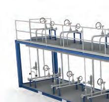
Gas and Heat S.p.A. is an Italian company specialising in the design and construction of cryogenic systems for the transport and storage of LNG and alternative fuels. With over 70 years of experience, it combines innovation and reliability to drive the energy transition.


Managing Editor
James Little james.little@palladianpublications.com
Senior Editor
Elizabeth Corner elizabeth.corner@palladianpublications.com
Editor Jessica Casey jessica.casey@palladianpublications.com
Editorial Assistant
Abby Butler abby.butler@palladianpublications.com
Sales Director
Rod Hardy rod.hardy@palladianpublications.com
Sales Manager
Will Powell will.powell@palladianpublications.com
Production Designer Siroun Dokmejian siroun.dokmejian@palladianpublications.com
Head of Events
Louise Cameron louise.cameron@palladianpublications.com
Event Coordinator
Chloe Lelliott chloe.lelliott@palladianpublications.com
Digital Events Coordinator
Merili Jurivete merili.jurivete@palladianpublications.com
Digital Content Assistant
Kristian Ilasko kristian.ilasko@palladianpublications.com
Junior Video Assistant
Amélie Meury-Cashman amelie.meury-cashman@palladianpublications.com
Digital Administrator
Nicole Harman-Smith nicole.harman-smith@palladianpublications.com
Administration Manager
Laura White laura.white@palladianpublications.com
Senior Web Developer
Ahmed Syed Jafri ahmed.jafri@palladianpublications.com
The LNG Industry team are back from Gastech, and reflecting upon a record-breaking show. More than 48 000 visitors over four days congregated in Milan 1 to discuss topics such as LNG, hydrogen, artificial intelligence (AI), and everything in-between.
One of the biggest talking points I heard repeated throughout the show was ‘low carbon’ energy. There was a big focus on decarbonisation from every angle, whether that be LNG producers, technology companies, or players in the shipping and marine industry.
There is obviously still a way to go in making LNG more environmentally friendly, but it was clear at the show that progress was being made, and new methods and technologies are being developed to help achieve this. Of course, LNG itself plays an important role in the energy transition, being considered as a ‘transitional fuel’ by many. However, one very interesting point was raised in a talk titled ‘Diversifying the energy mix with the adoption of LNG and natural gas to support a low carbon energy future’ 2: is LNG misbranded as a transitional fuel? The moderator raised this question, and I think it offers an interesting counter view. There’s no question LNG will play an important role in the transition to renewable and lower carbon sources of energy, but what happens once we get there?
Being branded as a transitional fuel makes it seem like there is an end date. But it is likely that LNG and natural gas will continue to play an important role in the future energy mix once other alternative fuels are more established, even if that may look different.
Attention now turns to ADIPEC 2025, taking place in Abu Dhabi, UAE. The overall consensus at Gastech was positive, and I’d imagine ADIPEC will continue this trend. With specialised industry areas including an AI Zone, Decarbonisation Zone, Maritime & Logistics Zone, and Digitalisation Zone, the conference is sure to encourage more conversations about key sectors within the industry that will play a pivotal role in ensuring the longevity and sustainability of LNG.
The Middle East is still to play an important role in the LNG industry, despite current geopolitical tensions. Although key regional importers (such as Kuwait, Bahrain, and the UAE) may be having their deliveries disrupted, Qatar’s LNG exports appear uninterrupted,3 and remains one of the world’s top LNG exporters. As Vinson & Elkins outline in their regional report at the start of this issue, the Middle East and North Africa may face uncertainty, but the region’s cost competitiveness, strategic geography, and abundant reserves position it well for strategic growth and deeper global integration.
You can pick up a copy of the October issue of LNG Industry at ADIPEC in Abu Dhabi, UAE, from 3 – 6 November 2025 and the Americas LNG Summit & Exhibition in Louisiana, USA, from 19 – 21 October.
1. ‘Gastech 2025 Concludes in Milan with Record Attendance, Cementing its Position as a Catalyst for Industry Collaboration, Investment, and Innovation’, Gastech Exhibition & Conference, (12 September 2025), www.gastechevent.com/press-collection/press-release/2025/september/ gastech-2025-concludes-in-milan-with-record-attendance-cementing-its-position-as-a-catalystfor-industry-collaboration-investment-and-innovation
2. SUZUKI, K., BARRY, A., LIAO, J., SIGNORETTO, C. and NAKHLE, C., ‘Diversifying the energy mix with the adoption of LNG and natural gas to support a low carbon energy future’, Gastech 2025, (10 September 2025).
3. PAGE, L., ‘Qatar’s LNG exports hit a record daily high on 15 June, despite South Pars attack’, Kpler, (18 June 2025), www.kpler.com/blog/qatars-lng-exports-hit-a-record-daily-high-on-15-junedespite-south-pars-attack
Fincantieri and Princess Cruises have celebrated the delivery of Star Princess, the second LNG-powered cruise ship in Princess Cruises’ Sphere Class, at the Monfalcone shipyard.
The ceremony was attended by Gus Antorcha, President of Princess Cruises, Mauro Bordin, President of the Regional Council of Friuli Venezia Giulia, Ester Fedullo, Prefect of the Province of Gorizia, Luca Fasan, Mayor of the Municipality of Monfalcone, Pierroberto Folgiero, CEO of Fincantieri, Biagio Mazzotta, President of Fincantieri, Luigi Matarazzo, General Manager of the Fincantieri Merchant Ships Division, and Cristiano Bazzara, Director of the Fincantieri shipyard in Monfalcone.
With a gross tonnage of approximately 178 000, Star Princess – sister ship to Sun Princess, delivered in 2024 by the Monfalcone yard – is the second largest vessel ever constructed in Italy and the second LNG-powered cruise ship that Fincantieri has built for this shipowner. It is also the second dual-fuel vessel, primarily powered by LNG, to officially join the Princess fleet. LNG is the best readily available, proven, and commercially scalable fuel for the maritime industry today that significantly reduces direct greenhouse gases and other atmospheric emissions and particulate matter.
Cedar LNG is preparing for the construction of its transmission line, which will deliver renewable power from the Minette Bay substation to the floating LNG (FLNG) during operations. Construction of the transmission line will take place in the Alternative Transmission Line Corridor, which was approved by the BC Environmental Assessment Office (EOA)-issued Amendment in April 2025. The alternative corridor offers several key benefits, including the protection of old forests and marbled murrelet nesting habitat, reduced effects on blue-listed ecological communities and wetlands, and shorter access road requirements.
Cedar has identified two potential enhancements that are the basis of an amendment request to the BC EAO and the Impact Assessment Agency of Canada (IAAC). The first is to provide workforce accommodations aboard the FLNG during operations to ensure a specific number of trained individuals are aboard the vessel at all times, should there be an incident or emergency. As such, Cedar is requesting an amendment to house approximately 80 workers aboard the vessel, which represents less than 50% of the operational workforce.
Additionally, advancement of engineering design has identified the opportunity to increase the project’s permitted liquefaction capacity from the previously approved 400 million ft3/d of natural gas to 500 million ft3/d.
Sempra has announced that Sempra Infrastructure Partners has reached a final investment decision (FID) to advance the development, construction, and operation of Port Arthur LNG Phase 2. This new phase will include two natural gas liquefaction trains, one LNG storage tank, and associated facilities with a nameplate capacity of approximately 13 million tpy of US-produced LNG. Incremental project CAPEX at Phase 2 are estimated at US$12 billion, plus an approximate US$2 billion payment for shared common facilities, with commercial operations expected in 2030 and 2031 for Trains 3 and 4, respectively.
Funding for Phase 2 is supported by an equity investment led by Blackstone Credit & Insurance, together with an investor consortium including KKR, Apollo-managed funds,
and Private Credit at Goldman Sachs Alternatives. Together these investors have acquired a 49.9% minority equity interest for US$7 billion. Sempra Infrastructure Partners has retained a 50.1% majority stake in the project.
In addition to securing 100% equity financing, Sempra Infrastructure Partners has contracted Bechtel Energy Inc., which has received full notice to proceed for the project.
Sempra has also agreed to sell a 45% equity interest in Sempra Infrastructure Partners, one of North America’s leading energy infrastructure platforms, to affiliates of KKR, a leading global investment firm, with Canada Pension Plan Investment Board (CPP Investments).
The transaction is expected to close in 2Q26 – 3Q26, subject to necessary regulatory and other approvals.

The New Zealand government has assured the power companies in which it is a majority shareholder that capital is available to support investment in critical electricity infrastructure.
The government’s Energy Package focuses on investing in security of supply and building better markets to improve affordability.
The government is investing in energy security through a procurement process for a LNG import facility. By bolstering domestic gas supplies, LNG can help manage the impacts of dry years and keep the wider energy system up and running.
XRG P.J.S.C. has closed its acquisition of an 11.7% equity stake in Phase 1 (Trains 1 – 3) of the Rio Grande LNG project in Brownsville, Texas, the US. The investment is a strategic joint venture between XRG and Global Infrastructure Partners (GIP), a part of BlackRock.
Rio Grande LNG is one of the most ambitious LNG export infrastructure projects in the US with approximately 48 million tpy of potential liquefaction capacity currently under construction or in development, underscoring the role of the US as a major energy exporter. Construction of Trains 1 – 3 continues to progress smoothly, while final investment decision (FID) for Train 4 was achieved in early September 2025.
ärtsilä has signed a 10-year lifecycle agreement with OPearl LNG Ship Management. The agreement is designed to ensure the vessels’ maximum operational reliability by enabling flexible maintenance scheduling and optimising time between overhauls. The agreement was booked by Wärtsilä in 3Q25.
The scope of the agreement includes Wärtsilä’s Dynamic Maintenance Planning solution, which will provide flexible maintenance scheduling and extended maintenance intervals, 24/7 remote operational support, as well as contract management. It also includes Expert Insight, Wärtsilä's predictive maintenance solution that uses real-time vessel data to detect potential issues and assist in optimising operation and maintenance. By leveraging advanced artificial intelligence capabilities, Expert Insight will enable OPearl LNG Ship Management to identify anomalies early and address emerging issues proactively, thereby reducing the risk of unexpected downtime and ensuring smoother, more reliable journeys.
The 14 vessels covered by this agreement will be delivered between 3Q25 – 2Q27. Each ship will operate with two 6-cylinder and two 8-cylinder Wärtsilä 34DF dual-fuel engines, and will also each feature four Wärtsilä Gas Valve Units.
The transaction, initially announced in May 2024, is the company’s first gas infrastructure investment in the US, and reflects XRG’s long-term investment plans in the country. The project will employ over 5000 construction and trade workers at peak and will create 350 – 400 long-term operational jobs once in service. The transaction was undertaken through an investment vehicle of GIP, with XRG acquiring a portion of GIP’s existing stake.
X Molgas extends bunkering offering in Portugal
X Argent LNG accepted into FERC pre-filing
X Biogas Västra Skaraborg selects Nordsol technology for bio-LNG production

Baker Hughes leads the LNG industry in overpressure protection with innovative valve solutions that meet critical safety regulations.
Our pressure relief valves are designed for the most challenging applications – reducing unplanned downtime and costly incidents.
Diagnostic tools allow for predictive maintenance delivered by a global network of certified Green Tag™ service centers.
For more information, contact your local Baker Hughes representative or visit valves.bakerhughes.com
19 – 21 October 2025
Americas LNG Summit & Exhibition
Louisiana, USA
www.americaslngsummit.com
03 – 06 November 2025
ADIPEC
Abu Dhabi, UAE www.adipec.com
02 – 05 December 2025
World LNG Summit & Awards
Istanbul, Türkiye www.worldlngsummit.com
02 – 05 February 2026
21st International Conference & Exhibition on Liquefied Natural Gas (LNG2026)
Ar-Rayyan, Qatar
https://lng2026.com
09 – 10 March 2026
LNGCON 2026
Barcelona, Spain
https://lngcongress.com
10 – 11 March 2026
StocExpo
Rotterdam, the Netherlands www.stocexpo.com
01 – 05 June 2026
Posidonia 2026
Athens, Greece
https://posidonia-events.com
09 – 11 June 2026
Global Energy Show
Canada 2026
Calgary, Canada
www.globalenergyshow.com
Bank of Ayudhya Public Co. Ltd (Krungsri) has signed an agreement to provide long-term loan support to PE LNG Co. Ltd, a joint venture between PTT LNG Co. Ltd (PTTLNG), wholly owned by PTT Public Co. Ltd (PTT), and the Electricity Generating Authority of Thailand (EGAT), to enhance Thailand’s energy security.
PE LNG operates the LNG Map Ta Phut Terminal 2 (LMPT-2), located in Ban Nong Fab, Rayong Province. With a regasification capacity of 7.5 million tpy, LMPT-2 is a strategically important infrastructure project that will enhance Thailand’s energy security.
Galveston LNG Bunker Port, LLC (GLBP) has selected NV5 LNG Engineering Services, Inc. as EPC contractor to build its new LNG terminal. With an initial capacity of 360 000 gal./d (200 000 tpy), the terminal at Shoal Point in Texas City, Texas, will provide bunker fuel for ships in the greater Houston-Galveston region. NV5 LNG, a subsidiary of NV5 Global, Inc., is a North American leader in EPC for energy infrastructure.
Located on the Texas City Ship Channel in the Texas City industrial area, the GLBP facility will serve as a platform to supply conventional LNG, renewable LNG, and synthetic e-LNG by fuel barge to the rapidly expanding fleet of LNG-fuelled vessels.
The GLBP facility is optimally located to serve major ports, including Port Houston, the Port of Galveston, and the Port of Texas City. It is projected to come online in 2028 as the US Gulf Coast’s first dedicated LNG liquefaction facility for marine bunkering.
Nordsol has announced the construction of its first installation in Sweden. The plant will be built in Vara and is owned by Biogas Västra Skaraborg AB, a company founded and owned by 113 farmers and local entrepreneurs.
Construction of the plant will begin in autumn 2025, with commissioning planned for 2026. Once operational, the facility will produce up to 70 GWh/y of bio-LNG. The renewable fuel will be distributed by Redo Biosolutions AB, who will use it to decarbonise road transport in Sweden.
In total, the plant will process around 370 000 tpy of manure as feedstock for biogas production. This biogas will be upgraded and liquefied into bio-LNG with the support of Nordsol and EnviTec Biogas.
EnviTec Biogas will deliver its EnviThan upgrading technology to convert the raw biogas into biomethane. Nordsol’s Core technology will then further purify and liquefy the gas into bio-LNG. The systems will be tightly integrated to ensure low energy consumption, prevent methane slip, and allow for easy, reliable operation, all within a compact footprint. This setup is ideally suited for decentralised bio-LNG production, right at the source of the feedstock.


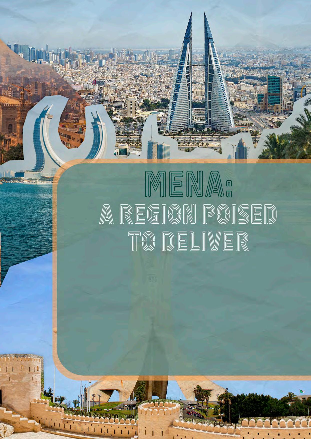
Chris Strong, Partner, Steven Wilson, Counsel, and Garrett Finch, Associate, Vinson & Elkins, explore the changing role the Middle East and North Africa region will play in the global LNG industry.
The LNG market in the Middle East and North Africa (MENA) faces renewed uncertainty following the June 2025 conflict involving Iran. Disruptions in the Strait of Hormuz briefly halted tanker movements and pushed up risk premiums, highlighting the region’s vulnerability as a critical energy corridor.
While key exporters like Qatar, Algeria, and Egypt continue to expand capacity, recent events may force a reassessment of supply security, logistics, and investment risk and reshape LNG dynamics across the region.
The MENA region continues to serve as a cornerstone of the global LNG market, currently accounting for over one-third of global LNG exports. Amid shifting global energy dynamics – marked by
European efforts to diversify supply and sustained growth in Asian demand – MENA producers are capitalising on their cost competitiveness, strategic geography, and abundant reserves.
The region is undergoing a transformative phase, with major infrastructure expansions, long-term supply agreements, and technological advancements positioning it for sustained leadership in the LNG sector. Qatar is spearheading this expansion with plans to nearly double its production capacity by 2030, while Oman is pioneering clean-powered LNG with its Marsa LNG project. The UAE is rapidly developing its Ruwais LNG terminal, which will more than double its export capacity and reduce emissions through electrification.
In North Africa, Algeria is aggressively increasing output to meet European demand, backed by new discoveries and pipeline connectivity. Egypt, facing domestic production declines, has shifted from exporter to importer, leveraging FSRUs to stabilise its supply and establish itself as a regional gas logistics hub. Meanwhile, countries like Kuwait, Bahrain, Iraq, and Jordan are enhancing import infrastructure and diversifying sources to meet rising domestic energy needs.
As regulatory uncertainty and cost pressures dampen the pace of North American LNG expansion, MENA is seizing the opportunity to capture greater market share. The region’s integrated strategies and growing flexibility are cementing its role as a global LNG powerhouse through the end of the decade.
Qatar remains the leading LNG exporter in the MENA region, currently producing 77 million tpy. Its dominance is underpinned by the North Field Expansion project, the largest LNG development globally, with the North Field East project expected to boost capacity to 110 million tpy by mid-2026, followed by the North Field South project, which aims to increase output further to 126 million tpy by 2028.
QatarEnergy has signed multiple long-term sale purchase agreements in the past with buyers in China, India, and Europe. Qatar has also deepened ties with Germany and Italy, positioning itself as a long-term supplier amid Europe’s pivot from Russian gas volumes. QatarEnergy has also progressed its LNG fleet renewal and expansion project, with more than 60 new LNG carriers on order from Korean shipyards.
These developments are supported by multibillion-dollar investments in infrastructure, including a US$6 billion contract signed with Chinese shipyards for LNG carriers expected to be delivered by 2029. Qatar continues to secure long-term supply agreements, recently entering negotiations with Japanese firms for up to 3 million tpy, thereby solidifying its role in both Asian and European energy security.
Additionally, Qatar has announced plans to trade 30 – 40 million tpy of non-Qatari LNG by 2030, expanding its influence in global LNG trading markets. Qatar has also enhanced its logistical flexibility through Qatar Gas Transport Co. Ltd’s joint ownership with Excelerate Energy of the FSRU Exquisite, which has been operating in Pakistan since 2015 under a long-term agreement with Engro Elengy Terminal Ltd at Port Qasim.
While playing a relatively marginal role in the LNG market in the MENA region, Oman’s LNG sector has taken a significant step forward with the ground-breaking Marsa LNG project
on 1 May 2025. This US$1.6 billion project, a joint venture between TotalEnergies and OQEP, will be the Middle East’s first LNG bunkering hub, powered entirely by electricity and supplemented by a 300 MWp solar photovoltaic plant. The facility is expected to commence operations in 2028.
Additionally, in 2024, Oman unveiled plans for the addition of a fourth LNG train to its existing facility at the Qalhat industrial complex in Sur, Oman, which is slated to increase its capacity by up to 3.8 million tpy. Leading international contractors are lining up for a key EPC contract from Oman LNG for the expansion.
In 2025, the UAE is rapidly advancing its LNG ambitions, spearheaded by the Ruwais LNG project – an electric-driven, low-carbon facility featuring two liquefaction trains, each producing 4.8 million tpy (total 9 million tpy), powered entirely by the national power grid, and set to commence operations around late 2028. ADNOC Gas has awarded US$2.1 billion in infrastructure contracts for pipeline, compression, and pre-processing facilities on site at Ruwais, part of a broader US$15 billion CAPEX roadmap intended to more than double its LNG output to over 15 million tpy. In June 2024, the project achieved final investment decision status, with Shell, BP, TotalEnergies, and Mitsui each holding a 10% stake and the project majority-owned 60% by ADNOC. ADNOC has already signed multiple long-term LNG supply agreements, including a 15-year, 0.8 million tpy deal with Osaka Gas and a 1 million tpy pact with Germany’s EnBW, underscoring global buyer confidence.
Yemen’s LNG sector remains largely inactive due to ongoing security concerns and political instability. The Balhaf LNG terminal, Yemen’s primary LNG facility with a capacity of 6.7 million tpy, has been under force majeure since 2015. Efforts to revitalise the LNG sector have been severely hindered by the broader conflict in the region. A notable event occurred on 17 April 2025, when the Ras Isa oil terminal (a critical piece of infrastructure) was targeted in US airstrikes intended to degrade the economic capabilities of the Houthi forces. Despite possessing significant natural gas reserves and infrastructure, the resumption of LNG activities in Yemen is unlikely in the near term due to persistent security and political challenges.
Algeria, which in 1964 became the first country to export LNG, maintains a steady LNG output of around 14 million tpy, but faces infrastructure constraints and investment shortfalls.
Algeria is scaling up its LNG and pipeline gas exports to meet strong demand from Europe. The state-owned energy company, Sonatrach, has set an ambitious production target of 200 billion m3/y by 2030, up from 137 billion m3 in 2023. This growth is supported by eight new field discoveries and ongoing investment in upstream infrastructure, including a US$2.3 billion expansion at the Hassi Rmel gas field.
Algeria’s strategic advantage lies in its ability to export gas both via LNG carriers and through direct pipelines to Europe, a dual export capability that strengthens its


position as a major energy partner for countries such as Italy and Spain.
Egypt’s LNG sector has experienced setbacks due to declining domestic production coupled with rising local demand. As of 2025, Egypt has transitioned into a net LNG importer, having contracted up to 60 LNG cargoes to satisfy its domestic needs. Recent agreements with Shell and TotalEnergies, valued at approximately US$3 billion, aim to bolster energy security through 2030.
While the government has launched exploration efforts in the Mediterranean and the Nile Delta, Egypt’s LNG ambitions remain constrained until new resources are proven. The pivot to LNG imports marks a reversal from previous export-driven momentum and underscores broader challenges in energy planning and infrastructure resilience.
FSRUs have become a critical part of Egypt’s strategy to manage the energy transition and address natural gas shortages. The Hӧegh Galleon (the country’s first operational FSRU, with a storage capacity of 170 000 m3 and a regasification capacity of 1 billion ft3/d) was brought online in mid-2024 at Ain Sokhna under an 18-month lease. Building on this success, a second FSRU, with a storage capacity of about 160 000 m3 and a regasification capacity of approximately 750 million ft3/d, is being brought online over summer 2025. These FSRUs are essential not only for meeting peak domestic demand – especially in summer – but also for stabilising Egypt’s power supply.
Additionally, Egypt’s FSRUs have extended their utility by enabling LNG transhipment to Jordan, helping Egypt emerge as a regional gas logistics and import hub in the Eastern Mediterranean.
Kuwait continues to strengthen its LNG strategy amid soaring electricity demand, particularly during summer peaks. In late August 2024, the country signed a second 15-year deal with QatarEnergy to import 3 million tpy of LNG – delivered ex-ship to the Al Zour LNG import terminal beginning January 2025 – adding to a similar contract initiated in 2022. The Al Zour terminal, commissioned in November 2021 and fully operational in February 2022, is the world’s largest LNG import facility and has since become a pillar of Kuwait’s gas infrastructure. It was purpose-built to accommodate large Q Flex and Q Max carriers delivering LNG. The terminal has continued to consistently receive full cargoes through 2025, after taking its spot as the Middle East’s largest LNG importer in 2024.
In April 2025, Bahrain took delivery of its first LNG import cargo – the first since its 5.9 million tpy regasification terminal was commissioned at the end of 2019 – signalling the country’s rising power needs. Bahrain is set to continue regular imports over the coming months, joining Dubai, Jordan, and Kuwait as LNG importers in the region.
Iraq, meanwhile, is rapidly shifting its energy sourcing strategy as it faces the imminent threat of an Iranian gas cut off. This strategic move follows the US’ decision to end a crucial waiver
that had enabled Baghdad to buy Iranian gas for electricity generation, increasing pressure on the Iraqi government to seek alternative energy sources.
To that end, Iraq’s Ministry of Oil is leasing FSRUs at Khor al-Zubair Gulf Port in Basra, expected to be operational later in 2025. Furthermore, plans are underway to construct a permanent regasification facility at Grand Faw by 2026. Iraq is also investing heavily in natural gas processing and flaring reduction. TotalEnergies began building a 50 million ft3/d gas processing plant at the Ratawi field in January 2025, as part of a broader US$27 billion energy infrastructure package. These developments align with Iraq’s strategic objective to boost domestic production and reduce environmental harm from gas flaring, with projects launched in 2025 expected to capture up to 290 million ft3/d of previously flared gas. Additionally, BP’s US$25 billion redevelopment deal for the Kirkuk oil and gas fields, signed in early 2025, includes significant investment in natural gas extraction and utilisation.
Jordan lacks a domestic LNG production industry and remains largely dependent on imported gas to meet its energy needs. Since 2015, Jordan has imported LNG via an FSRU located at the Port of Aqaba, with annual capacity of approximately 3.8 million tpy. Jordan is constructing its own land-based LNG terminal – the Sheikh Sabah LNG terminal at Aqaba – and from late 2026, Jordan’s National Electric Power Co. (NEPCO) will commence the long-term charter of an FSU from BW LNG to secure its national energy security needs. Pending completion of construction of the Sheikh Sabah LNG terminal, Jordan has signed a deal with Egypt to import gas via an Egypt-based FSRU until 2026.
The outlook for MENA’s LNG sector is one of strategic growth and deeper global integration. Driven by rising global demand for lower-emission fuels and the structural shift away from coal and oil, LNG will remain a critical component of the global energy mix – and the MENA region is poised to deliver.
In the coming years, Qatar’s massive North Field expansions and efforts to become a leading global LNG trader will reinforce its dominance. Oman and the UAE are developing next-generation terminals focused on emissions reduction and market resilience, while Algeria is doubling down on upstream development and export routes to Europe. Egypt’s pivot to LNG imports reflects evolving energy balances, yet also highlights its emerging role as a regional logistics hub.
Meanwhile, newer importers such as Iraq, Jordan, and Bahrain are investing in FSRUs and long-term contracts to shore up energy security. Kuwait remains the region’s largest LNG importer, underpinned by the world-leading Al Zour terminal.
Taken together, these developments underscore MENA’s increasingly diversified and resilient LNG ecosystem. With over US$50 billion in announced or ongoing projects, the region is not only expanding capacity, but also reshaping its role – from exporter and importer to global trader, hub, and clean energy innovator.
In the second part of a two-part article, Dr Lotfi Redjem Saad, Head of Heat Transfer Department at Technip Energies, and Andreas Knoepfler, Director Product Management at Wieland-Werke AG (Business Unit Thermal Solutions), analyse the use of enhanced heat transfer technologies in a real-world case study and its contribution to reducing greenhouse gas emissions for an existing LNG facility.
As the global natural gas liquefaction capacity continues to grow, reaching around 495 million tpy in 2024, the industry is increasingly focused on making LNG production more efficient, reliable, and sustainable. In part one of this article series, the development and deployment of dual-enhanced tubes in LNG pre-cooling heat exchangers was discussed, demonstrating their excellent performance and reliability, which have already contributed significantly to improving efficiency and operational stability.
Building on that progress, part two will explore how innovative heat exchanger design can further optimise plant performance, using a case study of a collaboration

between Technip Energies and Wieland. By enhancing heat transfer efficiency and reducing approach temperatures, the companies aim to increase LNG output, lower energy consumption, and minimise environmental impact. This partnership exemplifies how combining expertise and advanced technology can support the industry’s shift towards greener, more cost-effective solutions, advancing the global energy transition.
Since heat exchangers in LNG precooling trains play a major role in the operational performance of a LNG facility, it is a perfect opportunity to implement innovative
heat transfer technology. Propane chillers are one-pass design with the tube side stream of natural gas or mixed refrigerant (MR) operating in series. On the kettle-shell side, different pressure levels set the corresponding propane boiling temperatures. Consequently, the heat flux varies from tube inlet to outlet. Table 1 shows the representative conditions in a high-pressure (HP) propane chiller for a Gulf of Mexico project.
Because vapour production is proportional to the temperature difference, about five times more vapour is generated at the heat exchanger inlet. This leads to heterogeneous entrainment behaviour, raising questions about managing liquid carryover. Typical methods for this include:
z Dividing the kettle length into parts and the sizing shell diameter based on the most


critical section, relying solely on gravity, which is a very conservative approach.
z Adjusting nozzle sizes and locations along the kettle to match local vapour production, enabling efficient vapour removal, and preventing congestion, though this results in complex piping and stress analysis.
z Installing mist eliminators (Figure 1) horizontally and perpendicular to vapour flow, which forces vapour through wire meshes or perforated plates based on local vapour velocity. Computational fluid dynamics (CFD) studies may be needed to optimise mesh placement, considering disengagement space to limit pressure drop and maximise efficiency. This method stabilises vapour flow and makes nozzle placement independent of vapour generation.
Moving from plain or low fin tubes to dual enhanced nucleate boiling tubes results in lighter, more economical chillers (up to 50% shorter). When entrainment control relies solely on gravity, the separation volume must be maintained, which increases diameter as length decreases. This impacts fluid inventory and safety.
This article focuses in particular on using enhanced heat transfer technology – when using dual enhanced nucleate boiling tubes in gravity-based designs, it is like installing a Formula 1 engine in an outdated car. That is why Technip Energies (T.EN) and Wieland have developed ‘enhanced chillers’, combining advanced boiling tube technology (GEWA-PB) with optimised kettle design to create the most compact, lightweight solutions with low carbon dioxide (CO 2) emissions.
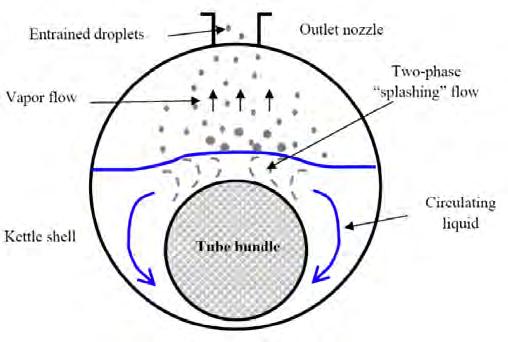
Chillers in propane precooling cycles of LNG plants are based on shell and tube heat exchangers, known as kettle type (K type per TEMA). The kettle vaporises liquid and ensures droplet removal to protect the compressor. The liquid (droplets) carried with vapour is expressed as a percentage or kilogramme of liquid per kilogramme of vapour and is crucial in kettle design. It involves the total liquid quantity, not droplets size.
The kettle reboiler consists of a tube bundle with hot fluid inside (Figure 2), immersed in a shell acting as a boiling pool and droplet disengager. When boiling occurs, two-phase flow circulates: liquid flows downward, vapour rises. Near the surface, splashing causes large droplets to fall back, while smaller droplets are entrained with vapour (entrainment).
Predicting entrainment is complex; research, such as from HTRI®, offers proprietary correlations linking entrainment ratios to vapour velocity, which depends on vapour flow and kettle geometry. Critical entrainment velocity (Vcr) marks the threshold where shear forces balance gravity, influencing droplet entrainment. Calculations involve vapour flow, physical properties, and iterative sizing of the kettle diameter.
To minimise entrainment, increasing volume or diameter of the kettle is necessary if tube length is fixed.
World Leaders in LNG precooling heat exchangers design and delivery
Reliable Partnership
Our longstanding collaboration with Wieland optimizes the performance of heat exchangers.
LNG Leadership
We are a trusted leader shaping LNG’s future for the past 20 years.
Low-Carbon Solutions
We drive efficient and sustainable LNG solutions for the energy transition.


Mist eliminators – wire mesh or vane types – are used to reduce kettle size.
They operate via inertial impaction, coalescing droplets for gravity separation. Their capacity is limited by flooding and re-entrainment, controlled by the gas velocity, often calculated with the Souders-Brown equation, using standard K values (Table 2).
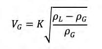
Where:
VG gas velocity (m 2/sec.).
K vapour load velocity (m 2/sec).
ρ L liquid density (Kg/m 3).
ρ G gas density (Kg/m 3).
Mist eliminators typically remove over 99% of droplets larger than 3 – 10 μm (mesh) or 10 – 40 μm (vane). Efficiency depends on design parameters like mesh density, plate spacing, and material.
Smart enhanced chiller (S.E.C.) designs represent the most compact heat exchanger with minimal refrigerant charge and volume, ensuring proper entrainment behaviour to
protect the compressor. The patented S.E.C. uses strategic placement of mist eliminators combined with a deflector plate. This offers several advantages over standard horizontal mist eliminator setups, including:
z Space optimisation within a smaller volume to meet Souders-Brown velocity.
z Higher efficiency through combining wire mesh and vane pack mist eliminators, with coalesced droplets directed downward to the deflector plate and drained back, reducing re-entrainment risk.
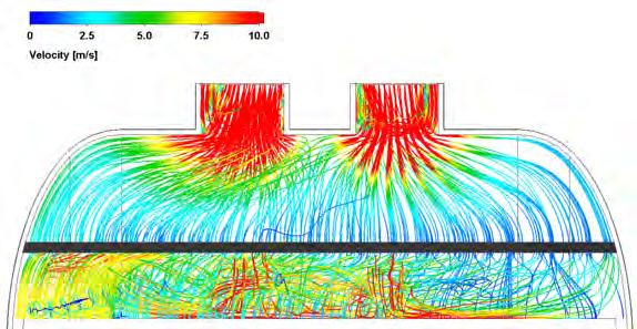
z A deflector plate at the bottom ensures even vapour distribution around the mist eliminator, confirmed by CFD studies and vendor validation.
z Unlike standard tubes, dual enhanced nucleate boiling tubes operate efficiently without flooding, maintaining a wet surface in the foam region. This enables lower liquid levels without impacting cooling, as confirmed by numerous site references.
z Proven eliminator technologies can reduce inlet and outlet nozzles on the shell side, depending on process conditions.
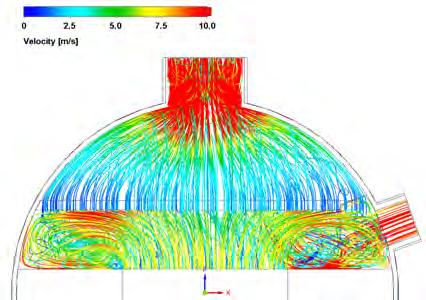
Overall, S.E.C. designs produce compact, cost-effective heat exchangers with a smaller carbon footprint by reducing material use. CFD is used for design validation, illustrating velocity fields in a chiller dome (Figure 5). Figure 4 compares conventional sizing with a smart enhanced design, showing potential kettle diameter reductions up to a factor of two, e.g. at HP stage.
Most precooling cycles worldwide are designed using a 3K temperature approach, which is the difference between the outlet FG or MR temperature and the propane boiling point of the chiller.
A generic case was developed to evaluate the performance of precooling cycles at three temperature approaches (3K, 2K, and 1K) on propane vaporisers.
The goal is to demonstrate the benefits of dual enhanced tube technology combined with the S.E.C. design, including improved LNG plant performance, refrigeration efficiency savings, and reduced CO 2 emissions.
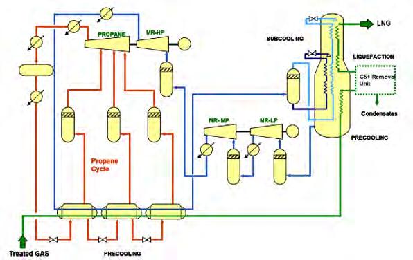
The case considers a 5 million tpy LNG train using C3MR technology, with refrigeration compressors arranged in a split-MR configuration (HP compression on the same shaft as the propane compressor) (Figure 3).
The propane precooling cycle includes four pressure stages (HP, MP, LP, LLP) for both natural gas and MR circuits. The LNG train is air-cooled under US Gulf Coast ambient conditions.
The study compares technologies at 3K approach, evaluates propane compressor power at 3K/2K/1K with S.E.C.-based vaporisers featuring dual enhanced nucleate boiling tubes, and assesses LNG capacity gains from propane power savings and tube technology in grassroots and revamp projects.
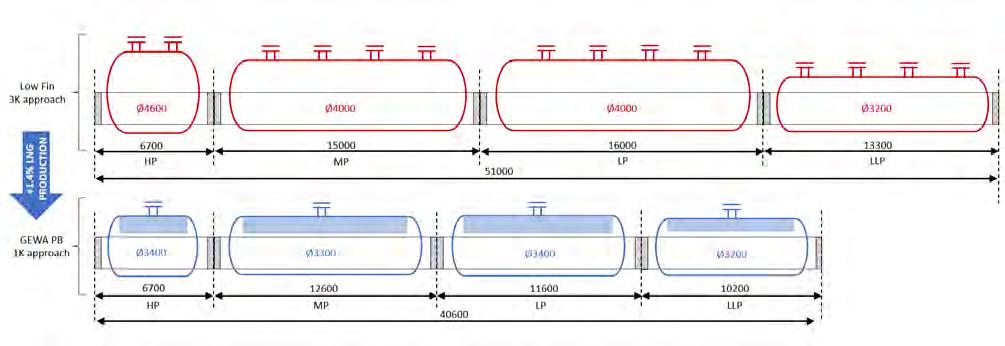
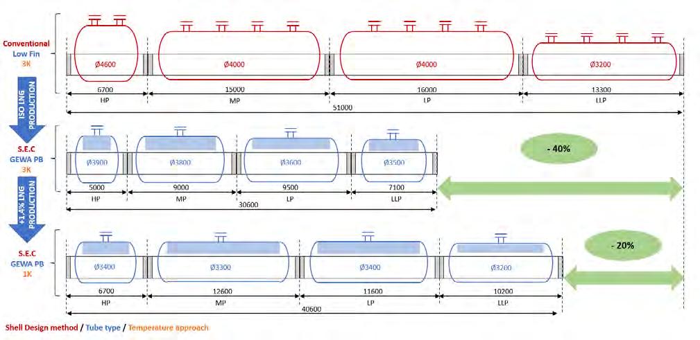
The first study, based on 3K approach temperature, confirms the already well-known benefits on the chilling train characteristics of using S.E.C. equipped with dual enhanced nucleate boiling tubes (GEWA-PB), compared to the conventional low-finned tube-based design (26 fpi low fin tube) (Figure 8).
For identical operating process conditions, C3 vaporisers of FG and MR trains, designed with S.E.C. and dual enhanced nucleate boiling tubes, are shorter by about 40% and lighter with a direct positive impact on the weights of piping, concrete for foundation, and steel for structure. Furthermore, the size reduction of the exchangers results in a 40% CO 2 emission reduction during the manufacturing phase compared to a standard design using low-finned tubes; additional savings of CO 2 for surrounding equipment can be added to this value.
The compactness of heat exchangers and use of dual enhanced tubes has an impact on the kettle size for the same liquid/vapour entrainment ratio compared to the outdated industry standards using conventional methods. S.E.C. designs result in an advantage on the kettle diameter, considerably reducing the exchanger dimensions compared to conventional methods (Figure 8). Thus, heat exchanger efficiency, compactness, LNG production rate, and overall greenhouse gas (GHG) emissions can be beneficially balanced.
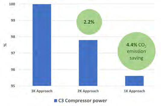
In a liquefaction unit, 30 – 35% of refrigeration power is used for precooling. Since propane compressor duty depends on the temperature approach on vaporisers and condensers, reducing these temperature approaches can improve cycle efficiency by lowering the compression ratio.
Nowadays, the industry is moving to 2K temperature approach in the chilling trains. Nevertheless, with conventional ‘low fin design’, the heat transfer performance decreases substantially and the use at temperature approaches lower than 3K becomes inefficient. Dual enhanced nucleate boiling surfaces become essential to improve nucleation, as part one of this article described.
Reducing the approach from 3K to 2K and 1K on propane vaporisers – while maintaining LNG capacity –can improve cycle efficiency by 2.2% and 4.4%, respectively, and reduce CO 2 emissions proportionally by decreasing fuel gas consumption (Figure 6).
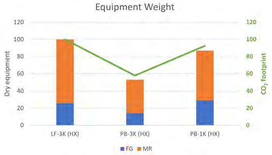
CO 2 emissions during equipment manufacturing are mainly proportional to the material weight. Based on former studies, 1 CO 2 emissions from heat exchangers have been focused around Scope 3 emissions, according to the Greenhouse Gas Protocol. 2
For an expected LNG capacity production at identical temperature approach, the change from conventional chiller design equipped with low-finned tubes to S.E.C. design equipped with dual enhanced nucleate boiling tubes leads to a vaporiser weight reduction close to 45%, reducing manufacturing CO 2 emission by about 40% (Figure 7). Considering a reduced temperature approach from 3K to 1K, the material weight and thus CO 2 emissions from heat exchanger manufacturing remain lower than conventionally designed, equipped with low-finned tubes at 3K temperature approach. This can be as high as 15% and 8%, respectively. In addition, it should be noted that propane compressor energy consumption can be lowered by 4.4%.
In the case that this compressor is driven by a gas turbine without CO 2 capture, around 4.4% less CO 2 emissions are recorded. At the liquefaction unit level, it is a CO 2 emission reduction of 1.1% considering that propane compressor power represents about 33% of the whole energy consumption of this unit.
T.EN and Wieland have developed a comprehensive knowledge in designing highly efficient chillers for LNG precooling by integrating dual enhanced nucleate boiling tubes (GEWA-PB). These advanced tubes, combined with innovative compact heat exchanger designs like the S.E.C., allow for better heat transfer performance and significantly more compact and lighter equipment. This means chillers can operate effectively at lower temperature differences – down to 1K – leading to improved cycle efficiency. As a result, propane compressor power consumption drops by up to 4.4%, which translates into significant energy savings and a reduction in CO 2 emissions. Additionally, the compact and optimised design reduces material use and overall plant footprint, supporting more sustainable and environmentally-friendly LNG production. Overall, this approach showcases how combining advanced tube technology with smart heat exchanger design can make a meaningful difference in reducing energy use and lowering the carbon footprint of LNG plants.
1. RÖNKA, M., RAMDIN Z., PROVOST, J., LANG, T., and KNÖPFLER, A., ‘Enhanced Reboiler for C3 Splitter Heat Pump Improves Energy Efficiency and Reduce CO 2 Footprint’, Hydrocarbon Processing, (March 2022).
2. ‘Corporate Value Chain (Scope 3) Accounting and Reporting Standard’, Greenhouse Gas Protocol, (September 2011), https://ghgprotocol.org/corporatevalue-chain-scope-3-standard
This article is based on a paper presented at LNG2023: KNÖPFLER, A., BUFFET, A., EL HAJAL, J., LANG, T., PROVOST, J., RAMBURE, N., and REDJEM SAAD, L., 3, 2, 1 … K, nucleation! or recent improvements in enhanced heat transfer is further reducing temperature approaches in LNG pre-cooling heat exchangers, (July 2023).
The other co-authors of this article are: Aline Buffet, Technip Energies; Dr Jean El-Hajal, Wieland Thermal Solutions; Thomas Lang, Wieland Thermal Solutions; Jérémy Provost, Technip Energies; and Dr Nicolas Rambure, Technip Energies.

Roly Juliano, Watlow, advocates for the role of medium voltage electric heating systems in decarbonising heating processes across the LNG lifecycle.
The LNG sector continues to evolve under the pressure of the global energy transition. While natural gas is often positioned as a bridging fuel due to its relatively low carbon intensity compared to coal or oil, producers and infrastructure operators are under growing scrutiny from regulators, investors, and customers. This extends beyond upstream extraction and pipeline efficiency to the less visible, but equally significant, domain of thermal energy use across LNG facilities. As operators seek new levers to reduce operational emissions and future-proof assets, the electrification of process heating is becoming a focus area.
Heating plays an essential role in virtually every segment of the LNG value chain. From initial gathering and gas conditioning to final regasification before distribution, thermal systems are used to prevent hydrate formation, regenerate process media, and ensure flow assurance and safety. Historically, these duties have relied on fossil fuel-based equipment such as gas-fired heaters, boilers, and water bath exchangers. These systems are not only carbon intensive but also pose challenges in terms of emissions permitting, maintenance complexity, and integration with modern digital infrastructure.
Electrification has emerged as a technically viable and increasingly economical alternative. Medium voltage (MV) electric heating systems in particular are being adopted in LNG projects due to their ability to deliver high thermal output with improved efficiency, lower installation costs, and reduced environmental impact. Among recent innovations, architectures such as POWERSAFE are demonstrating how
MV heating can be implemented in complex industrial environments.
The LNG process begins with the extraction and gathering of natural gas from onshore or offshore fields. At this early stage, large compressors are used to pressurise the gas for transport. Monoethylene glycol (MEG) is often injected to prevent the formation of gas hydrates in subsea or low-temperature pipelines. This MEG must be periodically recovered and reboiled, a process that relies on consistent and efficient thermal input. Electric heaters are well-suited to this duty, particularly when located in confined or hazardous environments where open flames are undesirable.
As the gas moves through treatment and liquefaction, several other thermal applications come into play. In acid gas removal, often referred to as sweetening, hydrogen sulfide and carbon dioxide are extracted using amine solvents. These solvents must be regenerated by applying heat through amine reboilers. Similarly, dehydration processes use triethylene glycol (TEG) or molecular sieves to remove water vapour from the gas stream. TEG reboilers operate within a moderate temperature range that aligns well with MV electric heating capabilities. Mercury removal systems, critical for protecting downstream aluminium heat exchangers from corrosion or amalgam damage, also require heat input to regenerate the adsorbent media.
At the downstream end of the chain, regasification terminals reheat LNG to return it to a gaseous state for pipeline delivery. This involves vaporisers and defrost systems, both of which depend

on reliable, high-capacity heat. In many of these duties, electric heating offers greater control precision and improved safety compared to fired equipment.
While electric heaters have long been used in industrial settings, traditional low voltage (LV) designs face limitations when scaled up for LNG operations. LV systems require step-down transformers to convert MV supply to the lower voltages used by the heater. This adds equipment cost and space requirements and increases the quantity and gauge of power cabling needed to manage high current loads. For installations in the 1 – 10 MW range, common across LNG facilities, these drawbacks can lead to significant capital and installation costs.
MV electric heating systems, typically operating at voltages such as 4.16 kV or 7.2 kV, overcome many of these issues. By connecting directly to existing MV infrastructure, they eliminate the need for transformers and reduce cable sizing requirements. The result is a smaller electrical footprint, faster installation, and lower materials cost. For example, a 5 MW heater installed with 400 ft of cabling can result in estimated savings of over US$375 000 compared to a similarly-rated LV heater. These savings scale with plant size and heater quantity.
Architectures such as POWERSAFE are designed to address the demands of LNG operations. They feature single-coil heating elements made from NiChrome alloys, encased in mineral-insulated sheaths and sealed with dual epoxy layers to protect against moisture ingress. These designs reduce internal temperatures, improving long-term reliability and extending service life. Lifespans beyond 200 000 hours are achievable, reducing maintenance intervals and improving asset utilisation. The systems are tested against stringent international standards for temperature control, corrosion resistance, and safe operation in hazardous areas.
Not all heating applications in LNG are equally suited to MV electric systems. For example, the regeneration of molecular sieves requires sustained high temperatures that may approach the operational limits of some MV heaters. In such cases, supplemental heating methods or hybrid configurations may be required. Understanding these boundaries ensures that electrification strategies are applied where they are technically and economically appropriate.
On the other hand, applications including TEG and amine reboiling are well-matched to the output range and control precision of MV systems. These processes benefit from stable thermal profiles, which reduce degradation of glycol or solvent media and enhance system uptime. Fuel gas conditioning, particularly in compressor stations where turbines require preheated fuel to prevent condensation and efficiency loss, is another promising area.
Defrost heaters in regasification terminals are another compelling case. These systems must respond quickly to changes in demand, often cycling in parallel with LNG send-out rates. Electric heating offers rapid response times and consistent performance under fluctuating load conditions. When integrated with plant automation systems, MV heaters provide real-time control and diagnostics, supporting adaptive operation and energy efficiency.
While electrification directly contributes to Scope 1 and Scope 2 emissions reductions, its operational benefits are equally important. MV electric systems simplify permitting and compliance by removing combustion from the equation. This is especially valuable in jurisdictions with strict air quality standards or in offshore environments where fire safety and ventilation constraints make gas-fired systems problematic.
Modern MV heater designs include built-in diagnostics, thermal monitoring, and remote access capabilities. These features reduce the need for manual inspection and support predictive maintenance strategies. When faults are detected, modular heater assemblies can be swapped or serviced with minimal disruption. Maintenance teams can be trained on safe handling procedures and diagnostics tools, reducing reliance on specialised external contractors.
Integrating MV systems with existing distributed control systems (DCS) is increasingly straightforward. Pre-engineered panels and controls packages are available that align with industry standards and can be deployed with limited customisation. This reduces engineering effort during the front-end design phase and supports smoother commissioning and plant start up.
As LNG operators begin to explore pathways for hydrogen blending, carbon capture, and green molecule integration, electrification of core processes becomes a foundational step. MV electric heating systems, by their nature, are compatible with renewable power sources and non-combustion
heating scenarios. This adaptability allows for phased decarbonisation strategies that can evolve over time without major reinvestment in thermal infrastructure.
Systems such as POWERSAFE are engineered with this future in mind. By avoiding fuel combustion and integrating seamlessly with grid or local renewable sources, they align with corporate ESG objectives and enable participation in emerging standards and certifications for low-carbon LNG. The ability to demonstrate verifiable emissions reductions from core operations also strengthens an operator’s position with financiers and offtake partners increasingly focused on sustainability metrics.
The decarbonisation of LNG operations demands both ambition and practicality. While large scale initiatives such as carbon capture or hydrogen fuel integration represent long-term goals, immediate gains can be made through the electrification of thermal processes. MV electric heating systems provide a reliable, efficient, and scalable pathway to reduce emissions, simplify operations, and extend asset longevity.
By targeting applications such as glycol reboiling, fuel gas heating, and LNG vaporisation, operators can make measurable progress towards emissions targets without compromising system performance. Technologies such as POWERSAFE demonstrate that the tools to decarbonise are available today and can be deployed within existing project and operational frameworks. As the LNG industry navigates its role in the energy transition, MV electric heating is set to become a cornerstone of future-ready infrastructure.

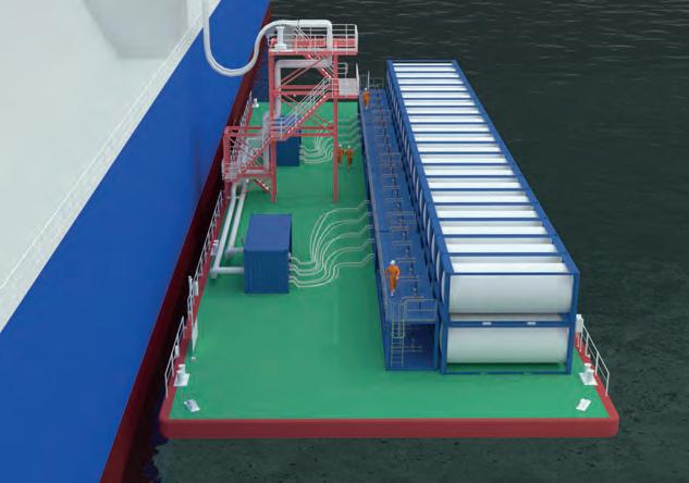
Eric Zielinski, Benjamin Mauries, and Mathieu Buschiazzo, Saipem, describe a solution aimed at monetising offshore gas in harsh sea conditions.
As per Shell’s LNG Outlook 2025, natural gas demand projections show a sharp increase in consumption, with a forecast rise of around 60% by 2040.
International events have also emphasised the need to diversify the sources of natural gas across the globe and evidenced the key role of LNG. LNG allows flexibility between production and consumption locations and is bound to be essential in this gas surge demand context.
However, increasing overall LNG production might be impacted by resource constraints, as new ‘easy’ gas fields might not be so numerous. As a result, there is a need to unlock new gas resources, even in more difficult environments, such as associated gases or smaller gas fields.
Concerning offshore fields, previous liquefaction projects were located in areas with relatively mild environmental conditions (such as limited significant wave height [Hs] or located nearshore). Some resources remain to be exploited, but lack sound and economically

viable solutions. Moreover, any new LNG production unit must now be designed in order to minimise its carbon footprint.
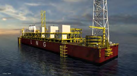
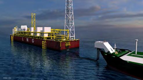
For these reasons, Saipem has developed a mid-size floating liquefaction solution dedicated to harsh environments, with high operability and efficiency at an ‘affordable’ cost.
The design developed is targeting the production of LNG from the following sources:
z Gas reservoirs having recoverable reserves of ~2 trillion ft3, with potential presence of heavier liquids.
z Oil production fields nearby (fixed platforms or FPSO), generating associated gas available for monetisation.
Harsh sea conditions with a 50% exceedance Hs value of 2.5 m are considered, which make typical LNG side-by-side
offloading no longer applicable, such as Brazil, southern parts of Africa, and some parts of Australia, among others.
The asset should be relocatable in case the gas in the initial field is depleted, which requires flexibility to be built into the design.
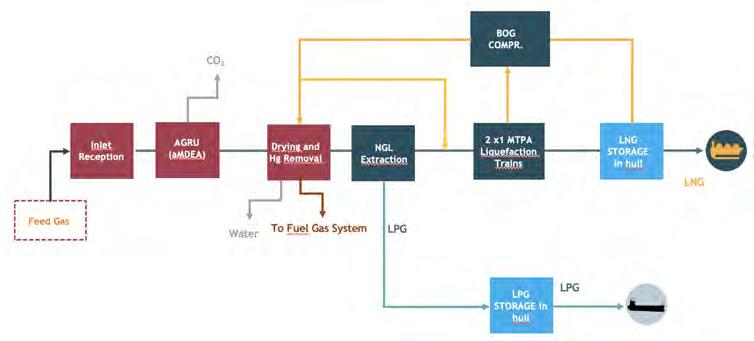
The natural gas throughput of these facilities is around 300 million ft3/d, which brings an LNG production of approximately 2 million tpy, with condensates produced as required. An LPG cut can also be produced, depending on actual raw gas composition and LNG high heating value (HHV) specification.
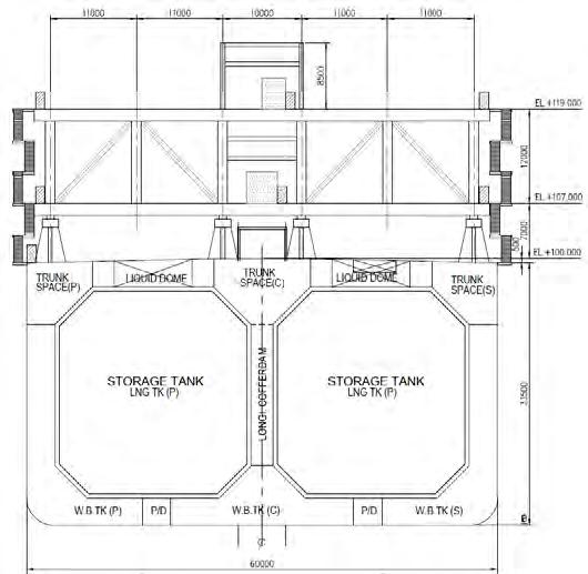
LNG storage capacity is 200 000 m3, which allows for an offloading operation every two weeks and makes it possible to accommodate a large variety of LNG carriers. Containment is of membrane type, with a double row of storage tanks to mitigate sloshing issues. Potentially, two storage tanks dedicated to LPG can be implemented, with an aggregate volume of 80 000 m3 The design life of the vessel is 25 years, without drydocking.
The floating LNG (FLNG) unit is turret-moored to minimise the loads and the motions and to provide more constant offloading conditions, thus increasing production availability. The LNG product (and potentially also the LPG product) is offloaded in tandem mode at the aft of the ship, using a Saipem/Trelleborg proprietary technology.
The required facilities to be implemented follow the standard sequence found in LNG production plants.
Also, the main utilities, such as power generation, steam, sea water and cooling water circuits, water treatment,
air and nitrogen, slops and drains, etc. are included together with safety systems (such as flares and vents, firefighting, cryogenic spillage collection and disposal, etc.).
To cope with the mid-size capacity and the limited CAPEX objective, a solution minimising the number of modules is preferred. Subsequently, the gas liquefaction technology selected must fit a ‘one train, one module’ concept, so it should be based on brazed aluminium heat exchangers (BAHX) to minimise weight and space and composed of two identical 1 million tpy trains. The technologies that can fulfill these requirements are SMR or nitrogen/natural gas expansion-based processes such as LiqueflexTM by Saipem.
The refrigeration compressors may either be gas turbine or electric motor driven; if gas turbine driven, each turbine exhaust would be equipped with an HP steam generator for maximum energy efficiency. The power generation consists of a combination of gas turbine generators and steam turbine generators. Low pressure steam extracted from steam turbines is used as a heating medium.
This arrangement allows a 60%+ thermal efficiency, and therefore a minimum carbon footprint linked to LNG production.
To allow a fast execution schedule and reduce CAPEX, complete process functionalities are kept as much as possible on the same module to minimise hook-up works at the yard.
Each process or utility module is transversal across the ship breadth and is supported by eight stools.
The central longitudinal piperack is integrated into the modules, minimising further the integration works.
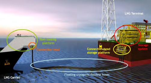
Harsh sea environments necessitate the use of an adequate LNG transfer system from the FLNG to the visiting LNG carrier.
The system developed by Saipem and Trelleborg performs this offloading operation in tandem mode, using floating cryogenic flexible hoses (FCFH), commercialised as CRYOLINE LNG by Trelleborg.
The FCFH is a hose-in-hose composed of:
z An inner composite hose made of un-bonded, multiple polymeric film and fabric layers trapped between two stainless steel wire helices which give the hose its shape, one being internal and one being external. Broadly, the film layers provide a fluid-tight barrier to the conveyed product and the fabric layers provide the mechanical strength of the hose. An optical fibre wrapped around the inner hose will be used to monitor the temperature all along the hose and ensure that no leak occurs during offloading operation.
An insulation layer which prevents the outer layer of the hose from getting too cold, thus preventing ice formation during LNG transfer. This layer also ensures the floatability of the complete hose.
To make nitrogen circulation possible, the insulation is porous in the axial direction. Indeed, this layer will be permanently slightly pressurised with nitrogen.
z An outer elastomeric layer to prevent any air or water ingress from the exterior. This layer also supports the axial loading.
Three identical 20 in. inner diameter FCFHs are implemented, two for liquid transfer and one for vapour return, allowing an offloading flowrate of 10 000 – 12 000 m3/h.
During non-offloading periods, the three FCFHs will be stored on a hose storage system located at the stern of the FLNG. The storage system mainly ensures:
z The storage of the FCFHs during non-offloading periods.
z The FCFHs reel/unreel procedure before/after an offloading operation.
z The complete emptying of the FCFH after the drainage procedure if required.
z The safe achievement of pre and post offloading operations prior to/after FCFH unreel/reel (gas replacement, warm-up, etc.).
z Preliminary inspection and maintenance operations.
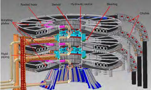
The storage system is composed of three stages on which each FCFH can be stored in a spiral wound configuration around a vertical axis (Figure 4). The rigid piping carrying fluid from/to the process units are in the centre of the hose storage system. At each stage, the FCFH is linked to the rigid piping network of the terminal using a cryogenic swivel.
The three FCFHs are linked together using a dedicated piece of equipment: the connection head. This connection head has two main functions:
1. To link the three FCFHs together and hence use a single operation to displace the FCFHs from the LNG terminal to the LNG carrier and vice-versa, thus speeding-up the operation.
2. To allow flushing operation of the liquid lines after an emergency disconnection by opening a loop between the LNG lines and hence retrieve the FCFHs on the LNG terminal with the minimum achievable LNG inventory.
The connection head includes stainless steel rigid lines, emergency release couplers (ball valve type), a by-pass line and valve, and several buoyancy modules.
Between offloading operations, the connection head is stored on a platform located at the aft of the FLNG where inspection and maintenance can be performed.
The design life of the offloading system is 25 years, except the hoses which have a design life of five years, based on 100 offloading operations per year. The whole system is maintained on site, with vessel assistance limited to change out of hoses after five years of operation.
The visiting LNG carriers must be equipped with a bow loading platform, so dedicated tankers are required. The bow loading platform mainly ensures:
z The safe pulling of the FCFHs from the LNG terminal to LNG carriers.
z The lifting of the FCFHs from sea level to the connection head dock area and the lowering to sea water.
z The connection/disconnection/emergency disconnection of the FCFHs (via the connection head).
z The handling of the connection head during the LNG transfer phase between the two units.
The bow loading platform is arranged with three decks above the LNG carrier main deck. The first level contains the winches (handling wires winches) used to displace and guide the connection head. The docking area dedicated to the connection head is also located at this level. Guiding structures and rollers are used to correctly position the connection head during the lifting operation. The second stage has the main function of supporting the piping (piping lines added to the typical LNG carrier) and the couplers used to connect the connection head piping to the LNG carrier piping. The third stage, located at an upper level, is equipped with the mooring equipment used during offloading operation (traction winch, fairlead, chain stopper, etc.).
All the systems involved in the cargo transfer can be controlled and monitored with a control panel located in the platform offloading control room.
A complete FEED, together with qualification campaigns of the system, have been performed and include:
z 3D mechanical design, including structural and piping stress analysis.
z PFDs, PIDs, surge analysis, and safety analysis.
z Enquiries to main vendors.
z Model test (1/10th scale) of the reeling system.
z Control and monitoring philosophies.
z Hydrodynamic validation of environmental conditions limits.
z Operational envelopes and availability.
z Validation of operating procedures with operators.
z Cost estimate.
A Concept Approval Certificate for the design has been delivered by Bureau Veritas.
This design will allow the visiting LNG carrier to be connected in seas with HS up to 4.5 m if equipped with DP2,
otherwise up to 3.5 m. The LNG carrier will remain connected and perform LNG transfer within a defined watch zone in seas up to 5.5 m with associated wind and current. A staged emergency disconnection procedure will be engaged in case the LNG carrier is drifting outside the allowable zone for LNG transfer. The nominal distance between the two vessels is around 100 m.
For the potential execution of such a project, Saipem could act as both main EPCIC contractor and technology provider of the liquefaction process (Liqueflex). Engineering and procurement services activities would be fully executed in-house. The hull could be fabricated in Korea or in China, where the topsides would be fabricated in Chinese yard(s), subcontracted or under partnership. The topsides integration could also be performed in China. Commissioning, offshore installation, and start-up could be performed by Saipem.
The implementation of the tandem offloading system would not impact the overall project schedule, as it does not result in long lead items and thus is not on the project schedule critical path.
The versatility of the described concept might help unlock offshore (or nearshore) gas reserves that remain stranded due to lack of sound technical solutions.
A mid-size, flexible, floating liquefaction platform which is adaptable to a large variety of weather conditions can help unlock these resources, and potentially produce valuable by-products.
Although necessitating visiting LNG carriers equipped with a bow loading platform, such modifications are minor and can be executed in many ship repair yards, and would not prevent them from loading and unloading in traditional terminals.
An optimised and integrated heat and power generation system enables the minimisation of carbon emissions linked to gas liquefaction.
1. ZIELINSKI, E. and DE PAOLIS, T., ‘Efficiency in congested places’, LNG Industry, (July 2020).
2. ‘Compact and intrinsically safe LNG liquefaction with integrated NGL extraction’, Gastech Exhibition and Conference, (September 2018).
Raul Llorens, Johnson Matthey, UK, explains how sulfur removal can be maximised with high-capacity absorbents without requiring any major modifications or CAPEX changes.
Hydrogen sulfide (H₂S) removal is a critical step in gas processing, essential for environmental compliance, protecting downstream equipment, and meeting pipeline specifications. As operating conditions and feed gas compositions evolve, customer requirements often change, sometimes necessitating adjustments and modifications to existing sulfur removal units (SRUs).
Using PURASPECTM technology, in combination with an innovative loading method, Johnson Matthey (JM) helped a
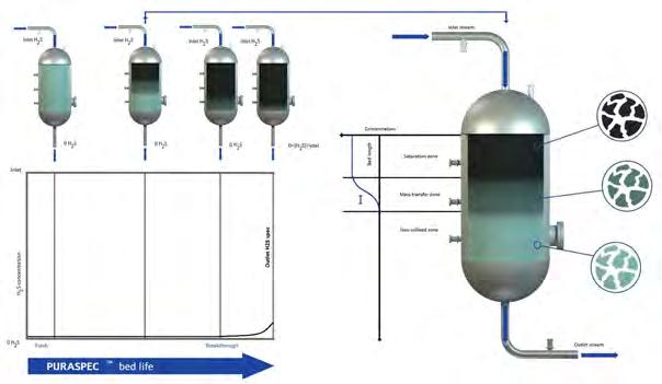
customer operating in the North Sea meet higher sulfur removal demand without requiring any major modifications or CAPEX. The customer operates SRUs for selective H₂S removal, followed by dehydration units downstream to remove water. The sulfur removal section comprises two vessels – one online and one stand-by – each filled with non-regenerable PURASPEC absorbent. The online vessel operates until the H₂S concentration is close to the specification limits, at which point the spent bed is taken offline and the stand-by vessel is
brought online. This alternating operation ensures continuous process flow.
In Figure 1, the typical evolution of the H₂S profile in the PURASPEC bed over time can be seen. As the bed operates, the saturated zone at the top expands, and the H₂S removal front gradually moves downward until breakthrough is detected at the outlet. The Mass Transfer Zone (MTZ) is defined as the section of the bed where the inlet H₂S concentration is reduced from its initial level down to zero.
Over the past 10 years, JM has collaborated closely with this customer to enhance the efficiency and capacity of its H₂S removal system in response to steadily increasing demand.
This article highlights how companies can maximise sulfur removal without experiencing CAPEX changes through a case study where JM’s customer in the North Sea increased its H₂S removal capacity by approximately 100%, all within the constraints of its existing system. This significant
improvement was achieved using JM’s highest-capacity absorbent to date, PURASPEC 1065, and implementing the atypical dense loading method instead of standard gravity sock loading.
With rising demand and more frequent change-outs expected, the customer switched from using JM’s PURASPEC 1039 and PURASPEC 1038 in a 70:30% ratio to the newly-introduced high capacity product in 2020, PURASPEC 1065.
By just switching to PURASPEC 1065, the company achieved a 40% increase in H₂S removal capacity, enabling it to maintain its existing change-out frequency despite a higher sulfur load.
The customer sought to further increase H₂S removal capacity, with the condition that no modifications be made to the existing system. To address this challenge, dense loading was proposed as a viable solution and the company chose to explore this approach in collaboration with CREALYST-Oil (France), a specialised catalyst handling company.
JM supported the initiative by supplying the necessary material to CREALYST-Oil to conduct testing with PURASPEC 1065, which ultimately confirmed that the product could be effectively dense loaded.
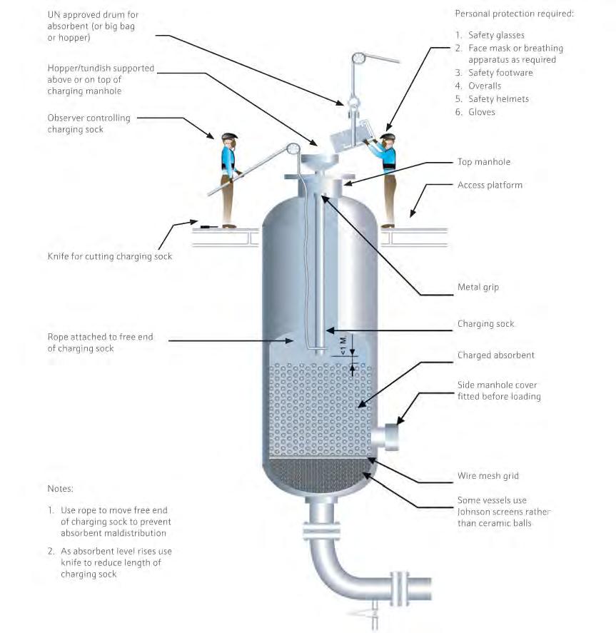
Sock loading consists of introducing the absorbent into the vessel using a lay-flat sock, which reduces the velocity at which the product falls. While this method does result in some particle attrition and dust generation due to inter-particle collisions, these effects are minimal when the procedure is properly executed. Years of experience have shown that any resulting dust or minimal product damage remains within acceptable limits and does not noticeably affect the performance of JM’s PURASPEC absorbents.
Sock loading is the most common method for loading absorbents and catalysts. However, the quality of the loading largely depends on the experience of the catalyst handling team as well as any specific constraints imposed by the vessel’s design or location. Consequently, significant variations in product levelling and density can occur from one charge to another. Moreover, achieving good levelling often requires confined space entry (CSE) into the vessel.
Dense loading is a method that uses a rotary device to impart radial velocity to absorbent particles as they are loaded into the vessel. This allows each individual particle to fall gently onto the top of the bed. When executed correctly, dense loading minimises product damage and attrition, while achieving higher packing densities because particles tend to orient similarly as they land. Additionally, it enables excellent levelling without the need for CSE into the vessel at any point during loading. CSE poses serious safety risks and requires specialised trained personnel to carry out the task. Work in confined spaces is a
common cause of fatalities and serious injuries in many industries. Fatalities involve not only those working in confined spaces, but also people who attempt to rescue them without appropriate training and equipment. When loading absorbents, a detailed risk assessment is conducted to ensure that the procedure is carried out safely and an emergency response plan is in place. Therefore, employing an alternative method that eliminates the need for CSE brings significant value to the safety and operation of the loading task.
This method is especially effective for increasing the density of extrudate cylindrical catalysts, as the extrudates align uniformly, allowing for more efficient packing within the bed.
However, unlike extrudates, PURASPEC 1065 is a granulated spherical product. Therefore, dense loading does not influence particle orientation, limiting the potential increase in density.
Another notable benefit of dense loading is the improved product distribution, which results in a higher concentration of granules and therefore a greater active surface area per unit volume of absorbent. Both factors can theoretically sharpen the reaction profile and enhance the product’s capacity, particularly in the bottom section of the bed.
To evaluate the potential increase in loaded density, a 1 l sample of PURASPEC 1065 was tested by the catalyst handling company using a small-scale tester device at its laboratory facilities. The results showed a 10% potential increase in density, which the customer deemed satisfactory to proceed with a full vessel loading trial at its terminal.
The initial trial took place in April 2023, in which the PURASPEC 1065 bed achieved a loaded density 15% higher than the typical density obtained by standard sock loading for this duty. This improvement exceeded the 10% increase initially projected by the catalyst handling company’s small scale tests.
This higher-than-expected density is particularly beneficial for the customer, whose primary objective is to maximise the capacity of the existing vessels. This outweighs the subsequent increase in pressure drop due to the higher loaded density, as no impact is expected on the downstream process.
Since the initial trial of dense loading with PURASPEC 1065, this loading method was repeated over six changeouts. This has provided sufficient data to fully evaluate the benefits achieved through dense loading of PURASPEC 1065. The average results from six loadings are presented in Table 1.
As shown in Table 1, the increase in loaded density resulted in a significantly more-than-proportional increase in capacity, which can only be attributed to the sharper sulfur removal profile achieved by dense loading.
To validate this theory, JM analysed the sulfur content in spent samples collected during each discharge and plotted the sulfur removal profiles for PURASPEC 1065 charges from May 2022 – November 2024.
In Figure 4, the black curves correspond to product loaded using the typical sock loading method from

May 2022 – April 2023, while the red curves represent dense-loaded charges from June 2023 – November 2024.
Table 1. Average results from six loadings
PURASPEC 1065: Dense-loaded vs sock-loaded

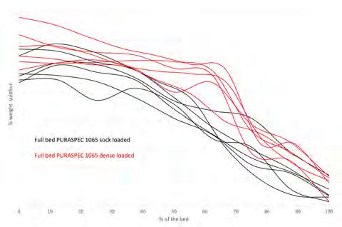
Note that for this duty the profiles and capacities reached by PURASPEC 1065 may vary depending on process conditions and the level of contaminants present in the stream. This variation explains the range of black and red curves observed in the graph.
The dense-loaded profiles clearly show an extension of the saturation zone to approximately 70% of the bed, representing a significant improvement over the typical 50% saturation observed with the sock loading method.
In addition, the sulfur profiles at the bottom 20% show a noticeably higher capacity with the dense-loaded method, contributing an extra 4% to the overall capacity of the bed.
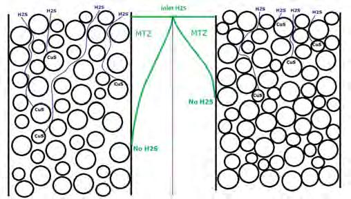
The most significant improvement from the dense loading method is the longer saturation section, which can be explained by the reduction in empty void space between the granules. This tighter packing forces more H₂S to react with the active granules. Figure 5 shows a diagram illustrating this effect. The drawing on the left represents a bed loaded using the sock loading method. The lower density results in more empty spaces between the granules, increasing the likelihood that H₂S molecules can bypass the granules and penetrate deeper into the bed without being removed. This is why the MTZ is more gradual or lazier.
The drawing on the right of Figure 5 represents a dense-loaded bed with significantly smaller voids between the granules. This tighter packing means that H₂S molecules are more likely to come into contact with the granules and be removed more quickly.
Finally, another added benefit of tighter packing is the greater driving force that facilitates easier flow penetration into the granules. This translates to more gas passing through the internal porosity of the granules, effectively shrinking the MTZ and allowing the granules to reach saturation more quickly.
In summary, the dense loading method has proven to increase the capacity of the PURASPEC 1065 bed well beyond what was expected from the simple increase in density.
The average capacity increase due to adoption of the dense loading method was calculated to be 47%, attributed to the following factors:
z A 17% increase due to higher bed density, resulting in a directly proportional increase in sulfur capacity.
z A 4% increase from enhanced sulfur removal in the bottom 20% of the bed.
z A 26% increase from the more extended saturation section, which now reaches approximately 70% of the bed.
By switching to PURASPEC 1065, the customer initially increased capacity by 40%. Then, by applying the dense loading method, the company achieved an additional 47% boost, resulting in a total capacity increase of 100%. This case study highlights how sulfur removal can be maximised with high-capacity absorbents without requiring any major modifications or CAPEX changes.

Analyze steady-state and transient uid behavior in piping systems.
Validate and optimize your process from concept to plant.
www.datacor.com/lng

Gareth Mugford, Product Manager, Eddyfi Technologies, highlights the importance of effective corrosion management in the LNG industry and explores how predictive maintenance techniques help to ensure operational resilience.

As the LNG sector expands globally, maintaining reliable and high-performing infrastructure is more critical than ever. Corrosion management remains a primary challenge affecting asset integrity, a persistent and complex issue. To address this, the industry is placing greater emphasis on technologies that enable efficient, reliable, optimal, and accurate large scale data collection to support proactive asset management.
Unplanned downtime resulting from corrosion-related failures can have significant financial and environmental consequences. Studies have estimated that the global cost of corrosion in the oil and gas sector runs into hundreds of billions of US dollars annually. This underscores the importance of corrosion prevention as both a safety measure and a key operational strategy.
LNG facilities operate under highly demanding conditions. These include extreme temperatures, elevated pressures, and exposure to both internal and external corrosive agents.
Additionally, environmental variability across different installation sites contributes to the risk profile. As a result, corrosion can affect a broad range of infrastructure components, including storage tanks, pipelines, processing units, and valves.
Historically, corrosion control has often relied on reactive maintenance practices – intervening only after damage is evident. However, this approach is being steadily replaced by predictive strategies designed to identify potential issues before they lead to failure. This shift reflects a broader move towards lifecycle asset management and operational resilience, emphasising early detection and data-driven decision making. However, it is essential that those predictive strategies are optimal. Today’s solutions must deliver high precision, high probability of detection (PoD), and high productivity.
Modern inspection technologies now play a central role in enabling early-stage detection of corrosion. These systems provide rapid identification of degradation mechanisms, real-time analysis, and validation of mitigation efforts. Armed with this information, operators can make more informed and timely maintenance decisions, thereby minimising long-term damage and unplanned downtime. Coinciding with this, it is essential to understand the capabilities of the techniques and technologies deployed.
The inspection technology landscape in LNG applications is broad, ranging from traditional radiographic testing (RT) to modern automated phased array ultrasonic testing (PAUT). While manual ultrasonic testing (UT) remains a staple for localised assessments, it lacks the speed, consistency, and high PoD required for large-surface corrosion mapping. In contrast, PAUT provides high-resolution imaging across wider areas and supports greater data reliability through improved detection capabilities, accuracy, and repeatability. When coupled with crawler-based systems, these inspections can be conducted with reduced human access, enhancing both safety and efficiency.

PAUT, a non-intrusive technique, is typically applied to the external surface of a component. It generates a 2D map of material condition, highlighting variations in wall thickness caused by corrosion and/or erosion. By recording data points at 1 mm intervals, PAUT produces fully encoded datasets that offer repeatability, auditability, and compliance with industry regulations. These datasets provide significant advantages over traditional manual UT.
The use of cross-sectional imaging modes, such as amplitude-based B-scans and D-scans, enhances visualisation by presenting enriched views of internal indications. This capability allows inspectors to easily distinguish between different types of material anomalies, such as inclusions vs small-diameter pitting. Collectively, these benefits reduce human error and significantly improve both the probability of detection and sizing accuracy.
Due to the larger footprint of PAUT probes, productivity is significantly increased, and the data benefits from enhanced resolution, resulting in high PoD and improved sizing accuracy. Recognition from inspection bodies and asset integrity engineers has led to PAUT becoming the preferred technique for in-service detection and characterisation of corrosion in pipes, tanks, vessels, and other critical assets. Deploying these non-destructive testing (NDT) methods through automated systems ensures complete data coverage of the designated inspection area, while reducing operator fatigue compared to manual methods.
Encoded scanning ensures that detected indications are precisely positioned relative to a mechanical datum point established during acquisition. This level of accuracy is crucial for correctly identifying flaw locations within a component and facilitates more efficient repairs or follow-up inspections.
Traditional manual inspections often rely on pen or pencil marks, or written annotations, to indicate flaw locations, which can lead to ambiguity or imprecise positioning when reviewing the report. With encoded data, the exact co-ordinates of a defect are captured and digitally recorded, significantly reducing the chances of misinterpretation.
Encoding enables greater precision in measuring flaw area, particularly in cases of corrosion mapping. By ensuring consistent probe positioning and data capture at defined increments, encoded scanning minimises human error and improves the reliability of defect characterisation.
Flaws can be represented in 3D imaging, offering a far more comprehensive understanding of their characteristics, orientation, and location within the inspected component. This visual representation allows asset owners and maintenance teams to make informed decisions regarding structural integrity, repair strategies, and long-term asset reliability, ensuring safety and operational efficiency. Encoding data acquisition allows recording the data, opening a whole new world of possibilities.
Collectively, these benefits make PAUT a preferred method for proactive integrity monitoring and asset management.
Recent developments from Eddyfi Technologies demonstrate how advanced instrumentation can improve inspection workflows. When the high-performance Cypher® instrument is paired with the battery-operated, automated NAV2 crawler, operators gain a solution that prioritises both productivity and simplicity. The embedded piloting capability enhances the crawler’s usability, enabling efficient deployment without the need for extensive training or complex set up procedures.
Automated corrosion mapping using PAUT supports high-resolution data acquisition with minimal manual intervention, without compromising on speed and maximising efficiency. These streamlined workflows assist qualified NDT personnel by simplifying the set up process and accelerating time from deployment to data collection –often referred to as ‘box-to-pipe’ speed. As a result, these systems are perfectly suited for a wide variety of inspection scenarios, including large scale campaigns.
By eliminating the requirement for scanner-specific familiarisation, the NAV2 crawler’s embedded autonomy allows for faster mobilisation across sites. This represents a meaningful step towards more autonomous and scalable
inspection routines, broadening access to advanced monitoring technologies throughout the LNG industry.
While PAUT has gained widespread acceptance, many inspection teams continue to rely on conventional UT methods. The automated platform remains compatible with single crystal and twin crystal conventional UT probes, allowing for flexibility in deployment. Although conventional UT generally offers lower productivity compared to PAUT, pairing it with an automated system can deliver comparable results – particularly when reduced data resolution is acceptable under the inspection plan and anticipated damage mechanisms.
In addition to corrosion mapping capabilities, the automated solution can be rapidly adapted to perform single-line scans, which are commonly used in storage tank inspections. Many operators utilise single-line scans at cardinal points around the tank circumference, complemented by targeted zones of detailed corrosion mapping. To support this approach, the highly versatile automated crawler can be reconfigured within minutes to switch between single-line scanning and large-area corrosion mapping. When weld inspection is required, the front end of the scanner can be equipped with up to six probes, enabling deployment of techniques such as PAUT, total focusing method (TFM), plane wave imaging (PWI), phase coherence imaging (PCI), and time-of-flight

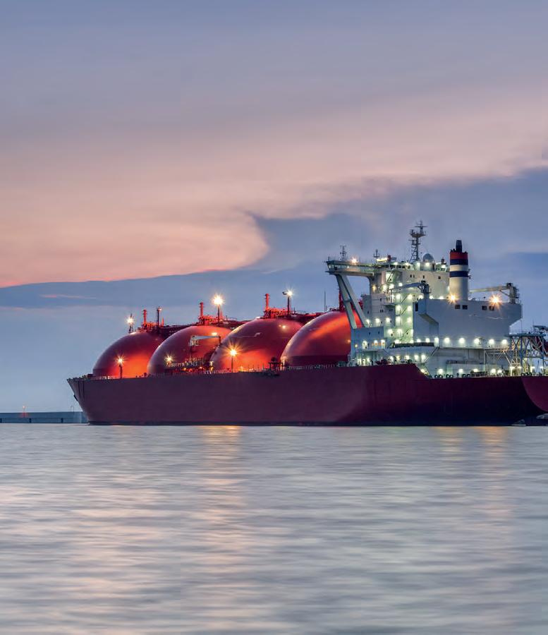
diffraction (ToFD) for both circumferential and longitudinal welds.
The benefits of the Cypher and NAV2 pairing extend beyond autonomy. Several onboard features further enhance operator experience and support more productive, reliable inspection campaigns:
z Intuitive workflow: Simplifies set up and operation, reducing training time and minimising user error.
z Efficient scanning speeds: Controlled motion ensures consistent coverage, minimising repeat scans and improving throughput.
z High-definition display: Large HD screen enhances visibility, enabling clearer identification of pitting, tight cracks, and inclusions.
z Enhanced Signal-to-Noise ratio (SNR): Delivers cleaner, more accurate data with reduced risk of crosstalk and electromagnetic interference.
z Remote expert access: Real-time remote login allows offsite specialists to review inspection data, provide guidance, or offer second opinions.
z Advanced analysis tools: Facilitate target localisation, speed up reporting, and support high-quality evaluations.
z Cloud-based storage: Enables instant data backup, seamless collaboration, and secure retrieval from any location.
z Offline analysis capability: Supports post-inspection data review and auditing by service providers and asset owners.
z Flexible tool compatibility: Easily reconfigured to accommodate a wide range of NDT techniques and probes.
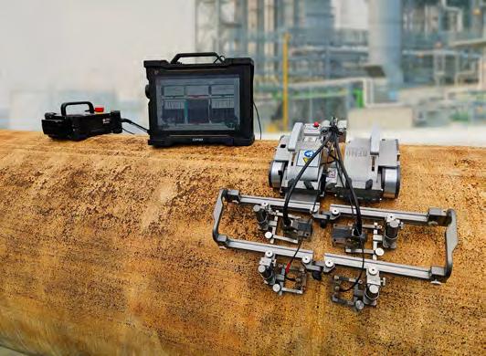
z HD camera integration: Provides visual confirmation and navigation support in hard-to-reach or obstructed areas.
z Weld tracking functionality: Ensures consistent data acquisition quality, especially in critical weld inspection zones.
These advantages are particularly relevant in LNG operations, where large infrastructure components and harsh service conditions demand comprehensive inspection coverage and accurate defect characterisation.
Historically, operators at LNG liquefaction plants relied on manual UT methods for periodic thickness measurements, particularly on piping systems and pressure vessels. While effective for localised assessments, these manual techniques often limited data density, traceability, and overall inspection speed. As the industry places greater emphasis on asset reliability and digital traceability, many operators are transitioning to encoded phased array UT workflows using crawler-based deployment systems. This shift has enabled broader data coverage, improved repeatability, and earlier detection of corrosion damage. In turn, it enhances confidence in inspection results, reduces the likelihood of unplanned downtime, and supports data-driven maintenance decisions across LNG facilities.
The adoption of the latest advanced PAUT instrumentation – particularly when integrated with automated scanning mechanisms – represents a significant advancement for the industry. By improving efficiency, accuracy, repeatability, and traceability, automated inspections offer substantial benefits to both technicians and asset owners. Technicians can dedicate less effort to manual set up and scan execution, enabling them to focus on analysing critical data. This shift not only enhances inspection quality but also leads to consistently high-quality reports, empowering asset owners to make more informed maintenance and repair decisions.
Looking ahead, the integration of automated inspection solutions with real-time analytics and machine learning is poised to further transform the corrosion management landscape. As asset data becomes increasingly centralised and standardised, predictive models will support more precise intervention planning – minimising risk and optimising lifecycle costs. These developments align with a broader industry transition towards digitalisation and integrated asset management systems.
As LNG facilities continue to expand and age, proactive corrosion management – driven by intelligent automation and data-centric workflows – will be essential for preserving asset integrity, ensuring personnel safety, and maintaining long-term operational continuity.
Craig
Harclerode, AF Expert Consulting, LLC, provides a recipe for LNG owners/operators to leverage a smart, asset-based data infrastructure and ‘layers of analytics’ strategy with a focus on data quality, contextualisation, foundational subject matter, and expert-developed streaming analytics to fully realise the power of advanced analytics and artificial intelligence.
Advanced analytics and artificial intelligence (AI) are rapidly transforming the LNG industry. Over 90% of the global LNG owner/operators have a foundational industrial data infrastructure in place – such as the AVEVA PI system and associated PI Assert framework – but most are only using a small percentage of its capability. The key enabler is fully leveraging this operational data infrastructure’s capability as a smart, asset-based operational digital twin to provide robust operational data quality, information management, real-time analytics, and proactive, exception based real-time decision support.
To unlock the full potential of advanced analytics and AI –including generative AI – this operational data and analytics asset infrastructure must be fully utilised and bi-directionally integrated with a multi-tenant cloud platform where advanced analytics and AI should be performed. Results should then be

operationalised by sending targets and forecasts back to the lower-level operational digital twin.
Organisations that attempt to adopt advanced analytics without first establishing this integrated data quality and analytical operational digital twin will face significant challenges and incur substantial lost opportunity costs.
This article outlines a practical roadmap for LNG owner/operators to evolve their current capabilities into a powerful, scalable platform for transformative AI-driven insights and operational excellence across the design, operate, and optimise lifecycle.
To realise this proven strategy for effective advanced analytics and AI implementation, there are three pillars that LNG owner/operators have used including NLNG, Cheniere, and Cameron LNG:
z A culture and strategy focused on standards-based industrial data quality and information management across the engineer-operate-optimise lifecycles starting in the FEED, addressing unstructured, simulation, and operational components, and how this data and information will be integrated and used to operate and optimise.
z Use of an industrial operational asset-based data model with integrated streaming (real-time) foundational analytics as a piece of a larger digital twin or ‘system of systems’ with an associated ‘layer of analytics’ approach.
z A focus on enablement of the LNG subject matter experts (SMEs) who can use self-serve ‘drag and drop’ capabilities to configure intelligent smart asset templates and, by doing so, capture their knowledge, share best practices, and eliminate the use of standalone spreadsheets.
Together, these three pillars form a comprehensive framework for intelligent operations in the LNG sector –enabling operators to improve safety, reduce costs, enhance reliability, and drive sustainability by fully leveraging advanced analytics and AI.
One of the most challenging areas to address and change is the establishment and nurturing of a culture that views and treats information as a strategic asset, recognising the critical role data plays in today’s data-driven, digitally-enabled industrial environment. In the industrial world, including the LNG industry, data is arguably the most important asset and should be treated as such as it enables employees, managers, and companies to make data-based decisions.
However, many LNG owner/operators fail to put into place or execute an industrial data management strategy. This is further compounded by a misalignment between the operational and information technology leadership as well as a lack of leadership in this area by executive management.
For industrial companies in general, and for LNG owner/operators specifically, for advanced analytics and AI to be transformative and generate sustainable value, a culture that treats data, context, and information as a strategic asset must be established, nurtured, and lead.
The leadership and responsibility should not be just delegated to the IT organisation or Chief Information Officer, rather the CEO and Board of Directors should have data and information quality and management as a strategic priority with associated baselines, KPIs, defined work processes, and ownership/accountabilities.
The LNG value chain, especially the feed gas and liquefaction facility, generates an enormous volume and variety of data, both structured and unstructured. This is further compounded with the velocity of data from control systems, programmable logic controllers, and remote sensors. Many solutions and applications fail to understand the complexity, criticality, volume, and velocity in the LNG value chain. A typical LNG
facility with three trains producing 15 million tpy can have over 500 000 ‘tags’ streaming at 1 – 5 sec., 24/7/365, generating petabytes of data. The number of tags is even larger for modular LNG train designs.
Without foundational data quality, asset-based contextualisation, and streaming (sub-second) descriptive, diagnostic, and simple predictive analytics, overlaying advanced analytics and AI will be at best problematic – and worse, result in reduced safety and sustainability and significant lost opportunity costs.
An industrial operational data infrastructure must be designed from the ground up to address these challenges and address real-time data issues such as missing or out of order data, data quality, and, most importantly, designed to keep the original fidelity of the time series data vs averaging to minimise storage or the ability to render quickly. Keeping the original fidelity of the time series data using advanced exception and compression is critical for improving the accuracy of higher-level analytics and AI.
Without a coherent information-focused culture and digital architecture starting in the FEED as a key digital strategy, advanced analytics and AI initiatives often stall. Engineers and data scientists spend disproportionate time on data wrangling, which slows innovation and dilutes business value.
The number of options and approaches in the marketplace of data management, advanced analytics, and AI are growing every day. Many are ‘solutions’ that require customisation, others do not address industrial data and information management challenges, but rather come from non-industrial domains. Others do not offer a hybrid cloud configuration where there is solid data and cyber security necessary for critical industrial processes, but rather propose to do everything in the ‘cloud’, the same cloud used for non-industrial general purpose applications and solutions.
The recommended and proven approach used across the industrial community including LNG is to use a hybrid cloud approach that is highly secure and designed for industrial purpose using an on-prem (meaning a single tenant cloud) with bi-directional integration to an agnostic Software-as-a-Service or multi-tenant cloud platform, which has the ability to facilitate seamless integration with a portfolio of advanced analytics and AI solution providers.
The highly secure, on-prem asset-based operational data infrastructure should include the following capabilities. These should function as a checklist for LNG operators developing and implementing their digital and analytics strategy, including advanced analytics and AI. Does the solution or capability provide:
z Structured, integrated data quality and usage lineage for industrial operational time series data and address challenges such as late or out of order data, modified data, or missing data with auto recalculation when used on analytics or expressions?
z Solid, industrial-focused, asset-based operational data management using SME configurable smart asset objects

industrial operations
designs

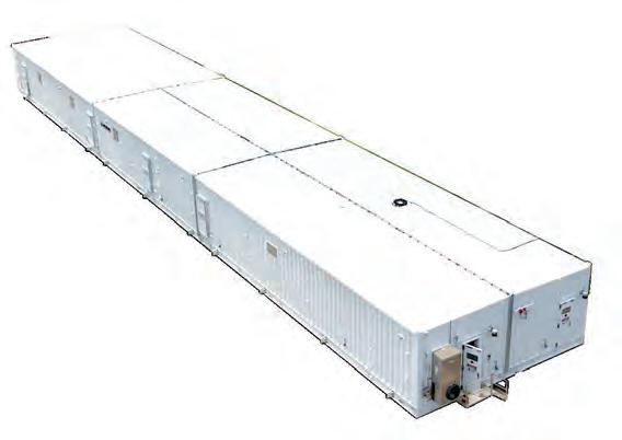
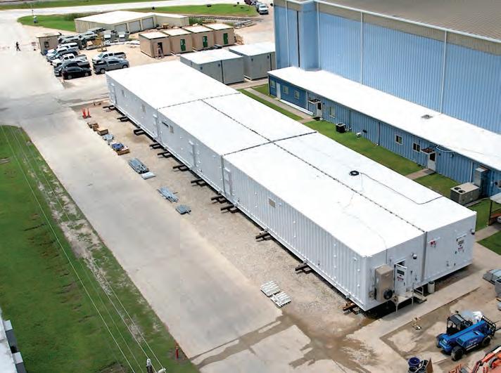

(templates) with the ability to govern at enterprise scale critical areas, such as units of measure with the ability to ‘cast’ between different ones, calculations and KPIs, dependency calculations, and a hierarchy that can be pivoted to provide persona or asset-based views?
z Linearisation of tags and measurements to optimise data transfer, add cyber/data security, and keep the original engineering fidelity of the data vs averaging which is critically important for accurate advanced analytics and AI applications, improving accuracy by over 5% in general, more in specific use cases?
z The ability to perform configurable, templatised ‘streaming’ calculations, events, and notifications – like a DCS without control as frequent as 1000 cycles/sec.?
z The ability to tune or develop expressions and event triggers and modify by back casting through the high-fidelity data archive or backfill modified expression-based calculations or KPIs? This capability is especially powerful when used by the SMEs to investigate events and determine causality or when a KPI is modified to ensure consistency.
z The development of virtual assets like product streams, molecules, yields, or categories and use with stoichiometry, first principals, or thermodynamics to determine, for example, the actual emissions at the molecular level of a fired heater or flare or to determine at the molecular level the efficiency of the refrigeration system?
z The ability to accept, store, and use forecasts stored as future data from advanced analytics and AI in the high-fidelity data archive and perform analytics such as a plan vs actual or trigger events or a notification when a deviation from forecasts is detected?
z Integrated statistical quality control to perform SQC analytics using SME configured SQC templates to determine control limit deviation, outside centreline, or other SQC based analytics?
z Support of parent-child asset relationships and enable pivot hierarchy views functioning as an ‘operational chart of accounts’ like the financial chart of accounts?
Another key ingredient to the recipe for effective advanced analytics and AI is the enablement and empowerment of the SMEs to capture and leverage their knowledge and wisdom as an integral part of the operational digital twin. As identified in the capabilities listed above for the industrial operational data infrastructure for analytics, the ability for the SMEs to, using configurable drag and drop capabilities, develop and evolve smart asset objects with associated expressions, event frames, and notifications is foundational for a ‘layers of analytics’ strategy to be fully effective and support effective advanced analytics and AI solutions.
Some LNG operators have elected to use closed, propriety solutions that tout the ability to be quickly installed and provide analytics, modelling, and advanced analytics.
However, these generally require modification and do not expose the details on how calculation and analytics are necessarily done, rather appear as a black box that creates dependency on the solutions provider. They also do not support a ‘best of breed’ open architecture.
Alternatively, the referenced agnostic, open and configurable industrial operational data infrastructure provides flexibility and the capability for the SMEs, with some coaching and use of smart asset object starter templates, to configure in a drag and drop, no code manner, smart asset object template and, in doing so, capture their knowledge, expertise, and wisdom with full transparency.
This is very powerful as the SMEs, with governance and support, can configure the foundational descriptive, diagnostic, and simple predictive analytics (analytics using formulas, expressions, or first principles) in the industrial operational data infrastructure. This analytical foundation can then be used to provide contextual, rich, and operational intelligence to higher level advanced analytics and AI. This approach is also very effective in supporting the data scientists and AI initiatives.
One of the challenges LNG owner/operators face with using closed, propriety solutions is their SMEs using Microsoft Excel for their operational engineering work resulting in data siloes, duplications of effort, and the inability to share best practices and capture SME knowledge. By moving the calculations done in Microsoft Excel to the operational data infrastructure, the Excel calculations are moved to being performed real time and then propagated to other applications. In doing so, this significantly improves data quality and manageability. This approach is in place today at leading LNG operators such as Cheniere Energy, Cameron LNG, and NLNG.1
To realise the full potential of advanced analytics and AI, a ‘layers of analytics’ approach enabling SMEs supported by an asset-based industrial data infrastructure that provides data quality, contextualisation, and foundational streaming analytics is required.
An operational data and analytics asset infrastructure that provides data quality and foundational analytics configured by the SMEs must be fully utilised to unlock the full potential of advanced analytics and AI. These analytics must also be bi-directionally integrated with a multi-tenant cloud platform. After this, results should then be operationalised by sending targets and forecasts back to the lower-level operational digital twin.
Without first establishing an integrated data quality and analytical operational digital twin, organisations attempting to adopt advanced analytics will encounter substantial challenges and significant lost opportunity costs.
This article has provided the blueprint for a practical roadmap for LNG owner/operators who are looking to evolve their current capabilities into a scalable platform with the power to provide transformative AI-driven insights and operational excellence across the design, operate, and optimise lifecycle.
1. HARCLERODE, C., ‘Balancing the energy trilemma’, LNG Industry, (November 2024).
ABB’s Energy Industries division, discusses how integrated automation, digitalisation, and electrification will futureproof the build out of new LNG terminals.
The LNG industry is entering a transformative growth phase. Some industry estimates say global demand for LNG is expected to rise by more than 50% by 2040,1 and between 2025 – 2028, the sector is on course to commission nearly five times more new capacity than it did in the previous four years.2
These statistics demonstrate the important role LNG plays in global energy security and in the energy transition. At the World Gas Conference 2025, held in Beijing, LNG’s expanding influence as a flexible energy source was reaffirmed by stakeholders. It is evident that as the share of renewables continues to grow in the energy mix, LNG is needed as a bridging fuel to plug intermittency issues and provide a scalable, reliable, and dispatchable power supply.
To meet the growing energy demand, there is an impetus to adopt technologies that improve efficiency and optimise

operations from construction to production. Modernising LNG terminals into highly automated, optimised, and electrified assets is paramount to operators remaining agile. This article will discuss the technologies that can deliver terminal infrastructure that is more resilient for the future.
Terminals are crucial assets in the global energy landscape, serving as hubs for the import, storage, and distribution of LNG. Life extension of these assets through retrofitting, maintenance, and upgrades can push their operating lifespan beyond 40 or even 50 years, and many plants constructed in the 1970s still operate today.
That said, modern LNG terminals are raising the bar for efficiency and optimisation. They are producing more
with less, and have dramatically increased the volume of LNG produced with each individual train, while lowering emissions. In this way, smart design, automation, digitalisation, and electrification can address the key challenges facing terminal operators, which include ensuring equipment reliability, maintenance, and safety; avoiding scheduling delays; reducing energy consumption and emissions; responding to demand fluctuations, and managing the workforce.
Digital solutions are innovating rapidly and continue to drive change in the LNG industry. Integrated and scalable terminal management systems, like ABB’s T-MAC Plus, streamline operations by automating processes such as access control for trucks and drivers at entry and exit gates. It also ensures data from meters and field elements are automatically shared to operator workstations, reducing engineer workload and improving safety.
In addition, digital twin technology plays an increasingly crucial role in the design and operational phases. Digital twins allow operators to simulate plant performance before construction is complete, enabling teams to optimise design, test modifications, and assess the impact of operational changes before implementation. Once operational, they provide performance testing, predictive maintenance, and operator training through simulation exercises. For new operators, this means hands-on experience in a realistic setting, allowing them to transition seamlessly into live plant operations with confidence.
As LNG projects become larger and more complex, modularisation is being adopted to mitigate cost overruns and schedule delays. The method is a bit like building blocks: sections are built individually in a factory and connected together on site. It is particularly advantageous when integrating automation, electrification, and digitalisation solutions because this equipment can be more easily integrated into prefabricated blocks. These are then floated to the location and incorporated into the project.
Modularisation is gaining popularity because it reduces site-based construction, which can be extremely complex at terminal sites, and reduces risks such as workforce exposure and system integration issues during commissioning. It is no
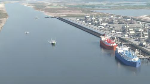
longer a niche option but a critical enabler for delivering fast, safe, and scalable LNG infrastructure.
The benefits of these technological approaches are multifold. Digital and automated systems collect and analyse a huge volume of data from which they can discover opportunities for operational improvements. These can include intelligent predictive maintenance, whereby the system collects data from different assets to inform the operator ahead of time when each asset will need to be serviced, reducing unexpected downtime.
At the World Gas Conference 2025, one of the speaker presentations said that there are 15 controllable parameters that operations monitor every minute. By automatically optimising these parameters, the company can produce an additional 5 million tpy of LNG – demonstrating the real, tangible benefits of digitalised optimisation.
Another, perhaps more visionary, benefit is integrating disparate systems so they can easily communicate with each other. At ABB, having the electrical control and automation system on the same ABB AbilityTM System 800xA® distributed control system (DCS) means two critical pieces of plant infrastructure are seamlessly integrated. ABB’s DCS was an integral part of the company’s scope awarded by Bechtel Energy Inc. for Phase 1 of the Rio Grande LNG facility in Brownsville, Texas. The project is the largest privately funded infrastructure project in Texas and is being developed by NextDecade Corp. ABB provided its DCS technology, alongside seven local equipment rooms and 14 substations, electrical control and monitoring system, and operator and power training simulators.
By utilising a comprehensive approach like this, more data can be accessed and analysed together to better inform operational decisions. Tools like digital dashboards allow different team members to share data, in real time, and use simulation to determine how and when different goals can be achieved.
Power management systems can be more easily optimised. In addition, thanks to the ability of artificial intelligence (AI) to self-learn, integrated systems can automatically adjust based on previous history, sometimes taking the inference of past interactions, to optimise the process.
Automated and integrated systems help to ease labour shortages that are becoming a challenge across heavy industries. Through remote operations and access to global technical support, system users get access to expertise without the expense and issues associated with global travel. Integrated, automated, and digitalised systems enable operators to spot and diagnose faults quicker. Unlike disparate systems that can often take weeks of investigation by engineers, integrated systems can quickly determine where a fault lies and offer a resolution.
The Queensland Curtis LNG (QCLNG) project in Australia features capacity of 8.5 million tpy of LNG, a nitrogen
rejection unit, and three containment LNG storage tanks, each of which has a 180 000 m3 capacity. ABB has integrated automation, safety, electrical distribution, telecommunications systems, and related equipment (including the 800xA DCS) for process control that is integrated with other plant and remote pipeline systems. The combined systems have resulted in reduced engineering and design cycle time, a shorter procurement cycle, improved engineering data management, and a lower cost of ownership.
The efficiency of the upstream gas gathering and compression facilities have been optimised and communications and remote operation throughout the 540 km pipeline network provided. The operator has total visibility of the entire system for operations, maintenance, and asset and alarm management. Upstream operations are integrated and controlled by a single DCS, which automates and optimises the main processes, minimising operating costs, and ensuring plant and personnel safety. The technology enables just four operators to manage all industrial, electrical, telecoms, and instrumentation from a single, 24 hour control room in Chinchilla.
While not suitable for every location due to the availability of power sources, e-LNG or all electric LNG is the route to enhancing energy efficiency and helping reduce emissions at terminals.
Once built, e-LNG plants can connect directly to the electrical grid and ideally leverage renewable electricity sources to power compressors, pumps, and refrigeration units. The primary source of emissions in an LNG facility is the gas turbines used to power compressors. e-LNG replaces these with large electric motors paired with variable speed drives. These motors are substantially more efficient; gas turbines typically operate at around 37% efficiency, while electric motors achieve over 95%. They also require much less maintenance – every five years, compared to annually for gas turbines. Moreover, because e-LNG facilities do not require natural gas to run turbines, they can produce additional LNG output. And by integrating electrification with automation technologies, it is possible to optimise operations and reduce energy usage across various processes.
Adoption of e-LNG has been gaining momentum for years. For example, Equinor’s pioneering Hammerfest project in Norway, when completed in 2006, was Europe’s first LNG export facility and the world’s first all-electric LNG plant. ABB supported the project with end-to-end expertise, including subsea technology and the integration of automation systems, including a fully integrated, central hub-controlled facility that improved safety and operational efficiency.
One of the challenges about e-LNG is reliability. This is particularly acute in harsh or remote environments, where terminal facilities are typically located, making them more susceptible to the elements including high winds and coastal storms.
Another potential challenge at some e-LNG facilities is the reliability of grid systems and the possibility of short
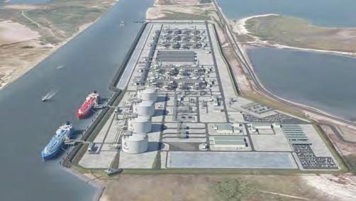
voltage drops. Fluctuations between 300 – 500 ms is enough to cause issues within the LNG train system and, once disrupted, it can take anywhere between 6 – 24 hours for the LNG process to reset, cool down, and begin producing LNG normally again.
To address these issues, ABB has developed advanced electrical and automation systems that detect and mitigate voltage drops, ensuring e-LNG plants maintain the same high reliability as conventional gas turbine-driven plants.
When ABB’s drive system is integrated with its automation system, the two can talk seamlessly together. If the drive sees a dip in voltage, rather than dropping to zero, it provides residual torque within the drive through a process called model predictive torque control. This solution is integrated in Kollsnes, Norway – one of the main gas processing facilities supplying Europe. Since 2019, the undervoltage management system has saved the facility 126 trips and increased the output of the facility by 8%.
Renewables, according to the IEA, currently make up about 30% of global electricity generation.3 While the technology is built out, natural gas is a viable energy source that can help meet the world’s energy security needs. LNG plays an important role in the energy transition, but LNG needs to be produced in the most energy efficient way possible. As the industry expands to meet the demands of the energy transition, technology will play a critical role in achieving measurable sustainability goals while improving operational efficiency.
Automation and digitalisation are the key tools being adopted today. Together they offer streamlined operations, low-cost analysis of data, increased visibility into process, reduction in maintenance, and increased production.
Through the deployment of electrification and digitalisation technologies – as the projects outlined in this article demonstrate – the LNG industry can start to decarbonise while maintaining energy security and affordability.
1. ‘Shell LNG Outlook 2024’, Shell, (2024), www.shell.com/whatwe-do/oil-and-natural-gas/liquefied-natural-gas-lng/lngoutlook-2024.html
2. ‘Global LNG Outlook 2024 – 2028’, Institute for Energy Economics and Financial Analysis, (25 April 2024), https://ieefa.org/resources/global-lng-outlook-2024-2028
3. ‘Energy System: Renewables’, International Energy Agency, www.iea.org/energy-system/renewables
Jim Taylor, AMECO, considers a strategic approach to planned maintenance in LNG facilities.
The LNG sector is entering a pivotal, high-stakes phase. Global demand for LNG is surging, propelled by multifaceted drivers. Ambitious energy transition goals that see natural gas as a critical bridge fuel, strategic diversification of energy supplies to enhance national security, and dynamic geopolitical shifts are changing global energy flows. Against this backdrop, LNG facilities across North America (particularly along the US Gulf Coast and Northwest Pacific Canada) are under immense pressure. They must not only maintain peak operational performance and ensure unwavering uptime, but also operate with maximum efficiency to capitalise on unprecedented market opportunities.
AMECO is actively tracking dozens of planned LNG terminals and liquefaction plants, a clear indicator of the industry’s robust expansion. However, bringing new mega-projects online is a multi-year endeavour. This protracted timeline means that the existing fleet of operating LNG liquefaction plants must remain in peak condition. As more new projects reach operational maturity, the industry’s focus is naturally shifting from the intense demands of construction to the equally, if not more, critical imperative of sustained maintenance. For LNG operators, planned maintenance is far more than a routine compliance task; it is a strategic move to reduce costly unplanned downtime, extend the operational life of highly valuable assets, and robustly protect profit margins in an inherently volatile global energy market.
Maintaining LNG infrastructure is no small feat. These facilities are sprawling, intricate, and technologically-advanced operations, characterised by highly interdependent systems and an array

of safety-critical components. The sheer scale and complexity mean that even a single, seemingly minor failure can cascade into significant operational disruptions. An extended shutdown or major equipment failure on an LNG train can translate into substantial lost revenue – not just from halted production, but also from contract penalties, reputation damage, and disruptions to the schedule of future shipments. The financial implications are immense, underscoring the vital role of continuous operational integrity.
Beyond the stark financial implications, robust and proactive maintenance is absolutely paramount for ensuring personnel safety and mitigating environmental risks. LNG facilities handle highly flammable cryogenics, and any compromise in integrity, whether due to equipment failure or human error, carries severe consequences. Effective maintenance programmes are the first line of defence against potential leaks, fires, or explosions, safeguarding workers, and surrounding communities. This dual economic viability and health, safety, and environmental (HSE) stewardship, is why LNG operators are eschewing reactive, ‘fix-it-when-it-breaks’ maintenance cycles and enthusiastically embracing an integrated, proactive, and predictive approach to outage planning and asset management.
This industry-wide focus on proactive maintenance undoubtedly brings significant opportunities for enhanced operational efficiency and competitive advantage. However, it also introduces a unique set of challenges that demand innovative solutions and strategic foresight.
The LNG sector, like many heavy industries, faces an acute shortage of experienced and certified craft labour (e.g. pipefitters, welders, electricians, and scaffold builders). An ageing workforce, coupled with a slower pace of new entrants joining skilled trades, means that finding qualified personnel for complex maintenance tasks, especially during large scale turnarounds, is increasingly difficult and costly. This scarcity often leads to inflated labour costs, impacts the quality and speed of critical repairs, and can extend outage durations, making efficient resource utilisation an absolute necessity.
Market demand and contractual obligations mean that every day an LNG facility is offline for maintenance is a day of lost revenue and potentially damaged customer relationships. Operators are under immense pressure to execute maintenance outages as quickly and efficiently as possible, often with shorter and tighter turnaround windows. This compression demands meticulous planning, seamless co-ordination, and zero tolerance for delays.
LNG facilities utilise highly specialised components and equipment, many of which have long lead times for procurement or require custom fabrication. Furthermore, specialised heavy equipment needed for large maintenance tasks (e.g. large cranes,

specific lifting gear, unique inspection tools) may not be readily available on short notice, especially in remote locations or during peak demand periods across the industry. This constraint necessitates advanced planning and long-term relationships with suppliers to guarantee access.
Many LNG facilities are massive, sprawling complexes located in industrial hubs that can experience significant congestion during major projects. Managing the movement of hundreds, if not thousands, of workers, tonnes of materials, and heavy equipment into and around these sites presents a formidable logistical challenge. Without streamlined logistics, congestion, delays, and safety incidents are almost inevitable.
The intricate network of interconnected systems within an LNG facility means that a maintenance activity on one component can have ripple effects across multiple others. Furthermore, the presence of safety-critical components
requires adherence to stringent regulatory and HSE standards and meticulous execution to prevent any potential risks, adding layers of complexity to planning and execution. These formidable constraints mean that a traditional, siloed approach to maintenance planning will not be sufficient. Success in this demanding environment hinges on achieving unparalleled operational efficiency and predictability. Every support function that touches the site, from core engineering to peripheral services, must be strategically co-ordinated and optimised.
One area often historically overlooked, or relegated to a tactical afterthought, in comprehensive outage planning is indirect services. These are the essential, yet often less visible, support functions that enable direct craft labour to perform their critical tasks. They include:
z Scaffolding and access solutions: Providing safe, efficient, and compliant elevated work platforms.
z Equipment rentals: Supplying specialised tools, heavy machinery, aerial lifts, and lighting towers, and other equipment.
z Tool management: Ensuring the right tools are available at the right time and place, in optimal condition.
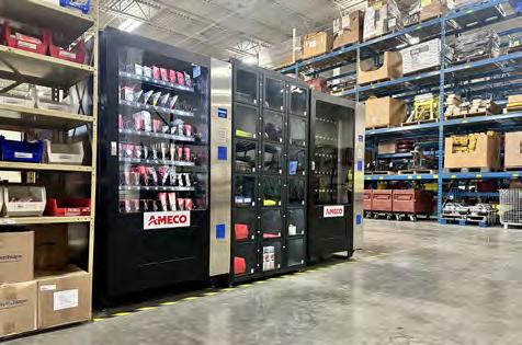
z Logistics and material handling: Managing the flow of materials, equipment, and personnel across the site.
z Temporary infrastructure: Setting up temporary offices, rest areas, communication hubs, and other support facilities.
When these services are managed reactively, through disparate vendors, in isolated silos, or left up to subcontractors to manage individually, they almost inevitably become a source of bottlenecks and inefficiency. Research and industry experts estimate that indirects make up somewhere between 30 – 45% of the total construction budget, depending on specific scope of work. This fragmentation leads to inflated budgets, creates rework, introduces unnecessary delays, and actively disrupts critical path work. Imagine a team of highly skilled technicians ready to begin a critical repair, but they are waiting for scaffolding to be erected, or the specific specialty tool they need is not in the tool crib, forcing them to spend valuable time tracking it down. These seemingly minor inefficiencies quickly compound, extending outage durations and driving up costs. That is precisely where a programmatic, integrated approach to indirect services makes an exponential difference.
For more than 75 years, AMECO has supported some of the most complex industrial projects and maintenance turnarounds globally with its approach to integrated Site Services®. The company has observed first hand how integrating a dedicated site services partner early in the planning process, whether by facility owners directly or by their primary maintenance contractors, can profoundly streamline outage execution, protect demanding schedules, and dramatically improve overall project outcomes. Its deep experience in supporting the construction and maintenance of LNG facilities has consistently demonstrated that proactive, centralised management of indirect services is not only a cost-saving measure, but a fundamental tool of operational excellence.
An integrated approach to these indirect services goes beyond simple provision of equipment. For the strategy to work, the services partner must act as an extension of the primary maintenance team. In the demanding environment of LNG facilities, this means achieving tangible, measurable benefits through a meticulously co-ordinated approach.
Scaffolds are often cited as one of the most challenging – but also most critical – indirect services. Working well in advance to plan scaffold builds, detect clashes early, and work dismantle/rebuilds into the provision of components can save time on erection schedules, as well as right-size the amount of scaffolding material that is needed on rent. Through integrated work scopes and meticulous planning, scaffold access is installed precisely where and when it is needed. This proactive approach eliminates non-productive time for craft labour, significantly reduces overall scaffold labour hours, and optimises associated rental costs.
Rather than craft labour wasting valuable time hunting for tools or waiting for a ‘gopher’ to return from a hardware store with consumables, an integrated and planned approach to tool and equipment management ensures tool cribs are optimally stocked
and consumables are aligned precisely to craft needs. Working with a partner can leverage advanced inventory management systems, including digital tracking to provide real-time visibility into tool availability and usage. This eliminates the ‘spread thin across vendors’ problem, minimises unnecessary tool rentals, and substantially reduces downtime associated with missing, broken, or improperly maintained equipment.
Any piece of rental equipment, from forklifts and aerial work platforms to specialised lifting gear, is essentially useless if it is not well maintained and ready to go when it is needed. Working with a dedicated resource to source and manage rental equipment project wide ensures every piece of equipment is ready for immediate deployment. Having one contractor co-ordinate equipment needs for the project eliminates unnecessary equipment redundancies and reduces congestion on the jobsite. This proactive management also eliminates costly delays stemming from equipment that is too large, too small, malfunctioning, or simply not available.
Managing the complex flow of materials, equipment, and personnel across a sprawling LNG site can be chaotic. By co-ordinating these indirect services through a centralised single point of accountability, jobsite congestion and risk can be mitigated, and overall equipment costs can be reduced.
Effective maintenance turnarounds require more than just tools and equipment. They also require a fully functional and supportive on-site environment. A well-planned maintenance shutdown will also require co-ordinating comprehensive temporary infrastructure solutions, including modular buildings for offices, break rooms, craft workspaces, and workforce hydration stations, as well as temporary utilities, lighting, and communication hubs. A well-planned and managed temporary footprint ensures that support functions operate seamlessly, enhancing worker comfort, safety, and, ultimately, overall site safety and productivity.
When indirect services are seamlessly integrated and managed by an experienced partner, craft labour spends less time waiting, searching, or dealing with logistical hurdles. They can focus on their highly skilled work, maximising their productive output on critical tasks. This direct correlation between efficient support services and craft productivity is undeniable, leading to more work accomplished within scheduled windows and ultimately, a more efficient overall outage.
While investing in a robust indirect services programme might seem like an added expense, the downstream savings are substantial. By reducing non-productive time, preventing costly delays, optimising resource utilisation, minimising rework, and avoiding premiums that come with emergency rentals or last-minute charges, the total cost of maintenance including labour, equipment, and opportunity costs from downtime,
is significantly reduced. This holistic approach transforms what might appear to be an operational expense into a strategic investment with a high return on investment, delivering predictable outcomes and sustained cost efficiencies.
The result of this strategic integration is clear: more predictable outages, significantly better labour productivity, and a demonstrably lower total cost of maintenance. This is not just about efficiency; it is about transforming operational bottlenecks into competitive advantages.
Planned maintenance will continue to be a defining factor in the long-term profitability, reliability, and safety of LNG facilities. As global energy dynamics continue to evolve and the demand for reliable LNG supply intensifies, the ability to execute efficient, predictable, and cost-effective maintenance becomes a core competency. By elevating indirect services from a tactical afterthought to a central component of a strategic maintenance strategy, LNG operators can do more than just manage challenges, they can proactively transform today’s maintenance challenges into operational wins and sustainable competitive advantages.
The future success of the LNG sector hinges on maximising the output and longevity of existing assets while safely and efficiently bringing new capacity online. A strategic approach to planned maintenance, powered by integrated indirect services and a trusted partner like AMECO, is not just the best practice, it is an essential strategic investment for any LNG operator aiming for peak performance in this critical and dynamic global market.


Elizabeth Corner
A conversation about the research, collaboration, and science behind safer, cleaner, and more efficient pipeline operations. Featuring Gary Choquette, Executive Director of Research at the Pipeline Research Council International (PRCI).
Gary shares his thoughts on:
• What PRCI does, and how it decides what to focus on.
• The Technology Development Centre in Houston – and why it’s a game changer.
• The industry’s readiness for hydrogen, CO2 and future fuels.
• Why collaborative research beats solo efforts every time.
• How PRCI supports transparency, safety and trust in the public eye
Episode Eight: AMPP
Episode Seven: UKOPA
Episode Six: TDW


Premium workforce accommodations for the most challenging locations.
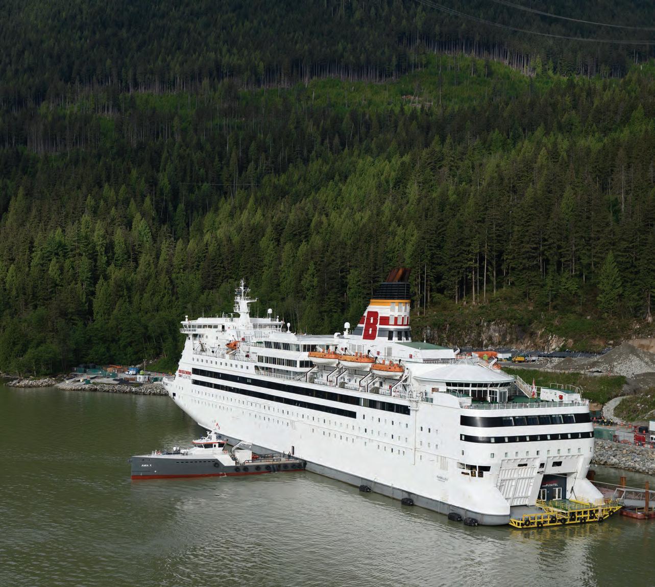
Bridgemans is the driving force behind your most ambitious marine projects. With deep industry experience and a hands-on approach, we provide a fully integrated system with three divisions: Bridgemans Floatels, Marine Services and Marine Construction.
With relentless attention to detail, Bridgemans Floatels are elevated in every aspect, customized to client specifications and held to the standards of a premium hotel. To expand our ability to deliver in even the most remote and challenging environments, our Marine Services and Marine Construction divisions provide marine transportation as well as construct docks, berths, breakwaters, and more. Bridgemans brings precision and an unwavering commitment to every project — Turning your ambition into real-world results.