
13 minute read
Precision Presplitting Optimisation


Dr Anthony Konya and Dr Calvin Konya, Precision Blasting Services, review some new methods for precision presplitting optimisation.


The ability to accurately and dependably presplit a final face is of extreme importance for the safety and economic viability of a mine. A proper presplit face is oft en attributed for reducing the likelihood of rockfalls from a project, but a deep understanding of the actual benefits is critical – not only in relation to the impact on safety, but also on capital and operating expenditures. Presplitting, in and of itself, is an expense for a mine, which can substantially increase the cost of the drilling and blasting programme, however, no mine-to-mill optimisation programme can be complete without an accompanying study on the economic benefits of presplitting. A presplit has three major functions at a mine, which will be discussed at length in this article. These objectives are: To reduce the rockfalls from a final face, which increases safety and reduces operating costs of clearing catch benches and catch berms. To allow for steeper face and pit angles, which increases overall profitability of the mine site. To complete the required objectives for the lowest cost achievable.


Reduction of rockfalls
The first objective of a presplit is to minimise the amount of rockfalls that occur from the final face – this is oft en discussed in how ‘clean’ the face is following the blast. The industry has a baseline understanding that the larger the percentage of half-casts (half borehole marks) left on the face, the better the presplit performs. A general industry rule of thumb is that if the presplit leaves over 90% of the half casts compared to the half casts that were drilled, then the presplit is successful. While a bit rudimentary, this method seems to be a reliable indicator of the number and the size of the rockfalls that will occur over a given amount of time. This is because the presence of the half-casts shows that the blast did not significantly overbreak into the rock mass behind.
The 90% half-cast rule is derived because it is the point at which the majority of rockfalls are eliminated from poor blasting conditions; not the point at which presplitting overcomes the geologic reasons rockfalls may occur, such as weathering mud seams or wedge jointing exposing on the face. It is critical to understand that blasting will not put rock back together or solve geologic situations, but it can avoid worsening the geologic situations.
Two simple reasons exist for insuff icient half-casts, in absence of geologic structural considerations. The presplit is either too ‘light’ (underbreaking with too little power) or too ‘heavy’ (overbreaking with too much power). The use of solely the word power, and not explosive power, is intentional and necessary because the design of a presplit is not as simple as a consideration of the explosive load. The consideration of the proper power of the presplit has then been well tied to the geologic matrix, more specifically the rocks Young’s Modulus.1,2
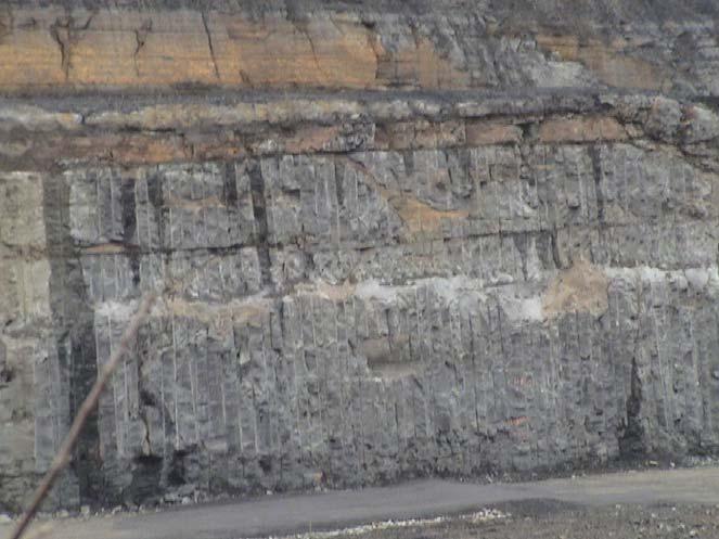
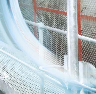
If it can be assumed that all other variables in the presplit formula are held constant, then the power of the presplit is solely a function of the explosive load. In this case, the explosive load can be correlated to the rock mass. The explosive load can then be calculated based on the given scenario to provide the proper presplit and half-cast percentage. The explosive load can then also vary in the borehole when diff erent geologic domains are encountered. For example, in one project construction in Virginia, US, five diff erent sedimentary rock types were encountered, including: limestone, sandstone, siltstone, mudstone, and shale. The explosive load was modified in the borehole based on the drill cuttings to achieve above a 95% half cast percentage; one blast section is shown in Figure 1.
Slope and pit steepening
Figure 1. A project undertaken by Precision Blasing Services in Virginia, US.
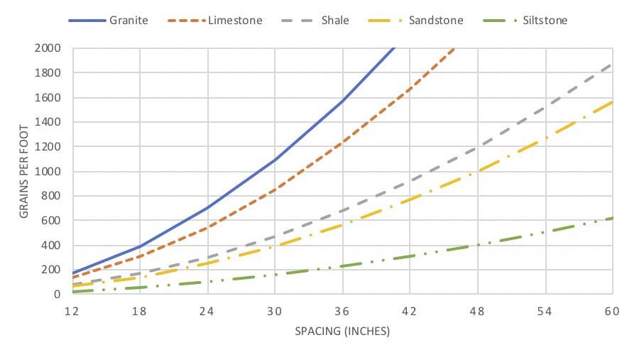
Figure 2. Precision presplit design with spacing variations to explosive load.
Two major considerations are made by the geotechnical and design team for a given mine: the face angle and pit angle. These will be used to ensure face and pit stability and are complex and multifaceted decisions, combining the need for safety (which improves with flatter slopes) with appropriate economic considerations to make the orebody profitable (which improves with steeper slopes). To grasp a general understanding, the face angle is typically set back (flattened) for two reasons: (1) it can help alleviate slope failures; and (2) it reduces the number and size of rockfalls that occur. When mining with competent rock, the primary reason the face angle is decreased is to reduce the number and size of rockfalls. This alone oft en flattens the pit angle for orebodies and leads to mining additional waste; but the problem is exacerbated because the flatter the face angle the larger the catch bench/berm area for mitigating the rockfalls which do occur. This means wider catch benches and catch berms in locations where personnel and equipment will operate, further increased pit angle, and the requirement of additional rock removal. The first step in the slope steepening programme is to reduce the overall number (and size) of rockfalls through a proper presplit design, focusing on the power to Young’s Modulus relationship. The second part of a slope and/or pit steepening programme (slope steepening) involves increasing the slope angle through a reduction in the risk of a slope failure. The major impact that blasting has on this process is not in improving slope stability, but in not worsening the slope stability. To accomplish this, two separate situations arise which need to be considered independently. These broadly can be diff erentiated as the structural and depositional problems that impact the blasting process.
Joint orientation
The structural problems are traditionally based on jointing, but may involve bedding and depositional cases. The traditional problem is with
vertical or near vertical jointing which intersects the presplit plane. Working with perfect vertical jointing, which is dipping at a 90˚, will be used to simplify the discussion; understanding that near vertical jointing dipping at other angles will have similar but more complex eff ects on the presplit formation. Depending on the strike angle of the joint(s) and the strike of the presplit plane, various situations can present themselves with varying eff ects on the presplit. These situations are based on work by Worsey and can be summarised as:3 Joints that have the same strike as the presplit plane result in the best presplit formation with no adverse effects. Joints with a strike angle which is less than 15˚ from the presplit plane striker result in extremely poor performance and likely no presplit plane will form. Joints with a strike angle which is between 15˚ and 60˚ from the presplit plane strike will result in overbreak beyond the presplit line in-between boreholes as the presplit breakage plane typically intersects joints at a 90˚ angle. Joints with a strike angle between 60˚ and 90˚ from the presplit plane will result in better performance with some minor overbreak; however, the presplit power will have to be greater to compensate for the joints stopping the fracture process. Joints with a strike angle 90˚ from the presplit plane will result in good presplit performance, but the presplit power will need to be greater to form full fracture.
This discussion has focussed on joint orientation to the presplit plane, which is important and oft entimes focuses on the design of the mine. The blasting team needs to understand the limitations involved, but, in most cases, they do not have the ability to make changes to the wall design or location. However, another important feature with the geologic structure does have a direct impact on the presplit design – the joint frequency.
The joint frequency
The joint frequency, in blasting, is typically referred to as the number of joints between two blastholes in a presplit line. The considerations of appropriate joint frequency require knowledge of the intended results of the presplit, the joints strike compared to the presplit plane strike, and other geologic features, such as weak seams which may need to be protected against. However, a general rule of thumb is that the joint frequency should be 2 – 3 for a good, long-term presplit and 3 – 5 for a short-term face. The blast design cannot change the frequency of the joints in a rock mass, but it can select the spacing between boreholes to control the joint frequency, and this will be the major consideration for ensuring good presplit formation.
The selection of the spacing based on the joint frequency is a common error in the design of a presplit, and is why at many sites a presplit design will work for part of a mine, but not the whole mine. This problem is further compounded by the fact that as the spacing changes the explosive load also must change, and typical design procedures such as
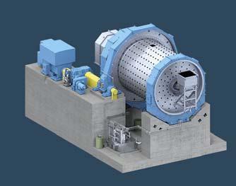


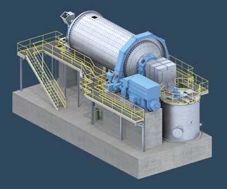
Toughest conditions, coarsest materials – time for EFFICIENT
PROCESSES
Autogenous/ Semi-autogenous mills
Slide shoe bearing mills
Trunion bearing mills
Visit us at christianpfeiffer.com
Split-Factor do not work to produce good results. This oft en leads mine operators to believe that certain geologic domains cannot be presplit, when in fact, in the majority of situations, the presplit can function eff ectively, but the tools being applied to the design process are inappropriate. To determine the appropriate explosive load based on spacing, the specific geologic domain and the spacing between boreholes must be taken into account. Techniques such as Split-Factor rely on a linear relationship between the explosive load and spacing, which has been shown to be an inaccurate representation. The relationship itself is actually quadratic in nature, which also has to consider the presplittability of the rock, oft en denoted by the Konya Presplit Factor. The Split-Factor approach would then either overbreak or result in no presplit development, depending on if the spacing is decreasing or increasing, respectively. Figure 2 shows example relationships for the presplit explosive load based on spacing, when spacing is the only independent variable.
Geologic deposition
The final part of the slope steepening programme would be the evaluation of the geologic deposition analysing weak features including open seams, mud/gravel seams, and weakly cemented joints or bedding planes – which traditionally have a dip angle below 60˚ and intersect the presplit plane. The detonation of a presplit results in large gas pressure inside of the borehole and, with too much pressure or too long retention time, these gases can flow into the weak seams and open them further. This can lead to the loosening of large blocks, which will be left hanging on the face. This can then also lead to large rockfalls or slope failures and can oft en be identified through large tension cracks behind the presplit. In addition, it can lead to faster weathering and increased water flow through the newly opened seams. The focus again is to ensure no movement or opening of these seams to preserve the original geologic strength and avoid degrading the face.
The protection of the weak seams can be accomplished in multiple ways, depending on the strength of the weak seam. In situations where mud/gravel layers or open seams are present, the best practice is to deck through the area, while leaving a small tracer line in the deck and to the second powder column, in order to ensure consistent initiation of the presplit powder column through the entire borehole. Another important feature is to ensure that the stemming retention time is greater than 8 msec. but less than 25 msec., in order to relieve the borehole pressure through venting and ensure that large, prolonged pressures are not realised on the weak seams.
The next step is to then utilise a technique which is now widely adopted in most sensitive presplit environments – precision presplitting. This entire article relies on concepts developed from the technique of precision presplitting, which is a specialty presplit design intended to use rock properties to achieve the desired results. The basis for this is to generate enough borehole pressure to cause the presplit to form by exceeding the rocks tensile strength through a hoop stress field, but not to generate so much pressure that it causes additional breakage, including overbreak and breakage of weak seams. The traditional methods of presplitting rely on utilising such large pressures that any rock will break, and this oft en leads to massive overbreak in weaker rocks. It is intuitive that to presplit a weaker rock, less explosive is needed than to presplit the strongest of rocks.
Precision presplitting
The final step of a presplit optimisation programme is to finalise a long-term design strategy which meets the sites objectives, follows the criteria discussed in this article, and achieves this at the lowest possible cost. This is an intensive procedure which is completed through a multivariable blast design process. The first stage is to understand not only the desired site goals, but also the realistic application at the site, including: explosive products, drilling equipment, and blast crew experience. This is critical, because a theoretical design that cannot be implemented is useless. The next part is a deep understanding of the site’s geology and current mining plan. Finally, the design process can begin by not only considering the desired intra-borehole pressure and associated hoop stresses generated, but also the economic considerations. For example, to achieve the same results one can decrease the explosive load or increase the diameter of the borehole diameter. These relationships are non-linear and oft en require advanced soft ware to analyse, but they can utilise the site-specific costs to develop the most economic solutions, which in turn can be practically implemented to produce the required results.
This process has been repeated at sites worldwide to achieve proper performance while improving site safety, steepening the mines slopes, and decreasing the mine’s presplitting costs concurrently. For example, at a Canadian diamond mine this process was implemented for the first diamond pipe pit. The original design utilised a face angle of 60˚ and benches of 50 ft (15 m). Through this design process, the face angle was steepened to 90˚ and the benches were increased to 100 ft (30 m) in height, while using borehole diameters up to 6.5 in. (165 mm). This also accompanied a steepening of the overall pit angle in both the kimberlite and granite, due to the ability to reliably achieve a competent, and safe presplit plane for the final walls.
Conclusion
Precision presplitting is a new technique in presplit blast design which has quickly taken over the blasting industry, due to its ability to work with and use of a mine site's geology. This has allowed for it to be used in everything from extremely weak mudstones and siltstones, up to the strongest of granites, gneiss, and basalts. The technique also has the ability to account for site jointing and structure to minimise backbreak, while ensuring a smooth, clean highwall remains. This had led to large improvements in mine eff iciency, including allowing for more stable highwalls and the steepening of pit slopes, in order to reduce overall mine waste. It has also led to major improvements in mine safety, by reducing the risk of rockfalls dramatically.
References
1. KONYA, A. and KONYA, C., 'Precision Presplitting Optimization',
Proceedings of the 42nd International Conference on Blasting and
Explosive Technique, (2016). 2. KONYA, A. and KONYA, C., 'Precision Presplitting - Explosive Variations with Spacing', Proceedings of the 43rd International Conference on
Explosive and Blasting Technique, (2017). 3. WORSEY, P., 'Geotechnical Factors Affecting the Application of Pre-Split
Blasting to Rock Slopes', University of Newcastle Upon Tyne, (1981).


